DOI:10.32604/cmc.2022.019516
| Computers, Materials & Continua DOI:10.32604/cmc.2022.019516 | |
| Article |
Flow Management Mechanism in Software-Defined Network
National Advanced IPv6 Centre, Universiti Sains Malaysia, USM, Penang, Malaysia
*Corresponding Author: Yung-Wey Chong. Email: chong@usm.my
Received: 14 April 2021; Accepted: 15 May 2021
Abstract: Software-defined networking (SDN) is a paradigm shift in modern networking. However, centralised controller architecture in SDN imposed flow setup overhead issue as the control plane handles all flows regardless of size and priority. Existing frameworks strictly reduce control plane overhead and it does not focus on rule placement of the flows itself. Furthermore, existing frameworks do not focus on managing elephant flows like RTSP. Thus, the proposed mechanism will use the flow statistics gathering method such as random packet sampling to determine elephant flow and microflow via a pre-defined threshold. This mechanism will ensure that the control plane works at an optimum workload because the controller only manages elephant flows via reactive routing and rule placement respectively. Reactive routing has reduced link bandwidth usage below the pre-defined threshold. Furthermore, rule placement has increased average throughput and total transfer to 238%. Meanwhile, the data plane switches will be able to forward microflows via multipath wildcard routing without invoking controller in greater responding time by 85 ms faster in two Transmission Control Protocol (TCP) traffic and achieved 11% and 12% higher total transfer size and throughput respectively. Hence, the controller’s workload reduced significantly to 48% in two TCP traffic.
Keywords: Software-defined network; controller; flow management
Software-defined networking (SDN) is a new concept conceived to solve these issues. Many research said that the SDN concept is the future of Internet architecture as it provides flexibility for users to manage the network. SDN provides an abstraction of the network, which allows network administrators to configure those network devices seamlessly across the enterprise networks. SDN has simplified the overall network in terms of management and provided a global view on the network topology. SDN manages the networks via centralised controller with the controller located on the control plane. The data plane that comprises switches or any packet-forwarding devices will forward packets to their destined egress point. Besides simplifying the network architectures, SDN is also able to improve Quality-of-Service (QoS) of an industrial cyber-physical systems, typically robotic cyber-physical system using SDN-based routing mechanism [1] and network slicing purpose [2]. Further, SDN has the potential to ease the manageability of the Multiple-Input-Multiple-Output (MIMO) system as there are plenty of research has been carried out to focus on improving the performance of massive MIMO system, for example, pilot contamination [3].
Although the future of SDN has been very promising, SDN faced challenges on a large scale or high-performance networks such as data centres or Internet service provider networks. As the network grows, OpenFlow controllers experience overhead issues and several researchers have proposed new architectures to resolve the dilemma. As for the first dilemma, OpenFlow used pull-based as their read-state mechanism, which causes interference with flow entries and consumes bandwidth during data gathering state. OpenFlow needs to generate 2N + 4 flow-entry installation packets with a minimum of two packets in each direction that are directed to and then from a controller [4]. Aggregating counters via wildcard mechanisms will undermine controller’s ability to manage specific elephant flows. As a result, all flows regardless of size will be forwarded to the controller. Additionally, controller like Floodlight not only utilises available link bandwidth but also focus on finding the shortest path. Thus, some flows might share the same path instead of being routed to an alternate path. As a result, link bandwidth consumption on the current path will increase.
Conversely, focusing on reducing the controller’s workload alone whilst neglecting security policy is not sufficient as security policy is the key factor in alleviating network workload. OpenFlow can transform security policy into a set of rules that can be installed in OpenFlow switches. Those transformed rules will then re-route specific flows to alternate paths whereas other flows on the default path remain unchanged. Thus, flows that are still being re-routed have the same destination point but use a different path. In other words, the security policy respects endpoint policy but relaxes routing policy. Rule placement can work with a firewall to help block flows based on specific services like File Transfer Protocol (FTP) and Real time Streaming Protocol (RTSP) in a more efficient way. Moreover, rule placement also helps in reducing bandwidth competition and utilise unused paths by re-routing elephant flows. In this paper, a new mechanism that reduces the controller’s workload by segregating responsibility to the data plane switches is proposed. Additionally, rule placement is embedded to handle abnormal elephant flows such as RTSP and FTP flows. This paper is an extension paper of [5].
This study focuses on offloading the controller’s workload and also ensuring the network flows are optimized. In brief, this study makes the following contributions:
• An optimized approach that reduce controller’s workload by segregating responsibility to data-plane switches
• Integrate rule placement to handle elephant flows such as RTSP and FTP flows for an optimized network bandwidth.
The current work is implemented in an emulated environment using Mininet as there is no hardware switch support. Further, the traffic generated for the test bed are single and two traffics to compare the impacts of number of traffic on the link bandwidth utilisation. Due to hardware limitation of virtual machine used to emulate network environment, the test beds can only be tested up to two traffics.
Flow statistics enables SDN architectures to manage their network resources in a more efficient manner by having a clear overview of network resources utilization.
2.1 Flow Statistical Collection Process
Packet sampling is one of the crucial factors that will affect controller’s workload and bandwidth consumption. Since sFlow standard is implemented in ASIC, sFlow can associate with OpenFlow to provide an integrated flow monitoring system [6] together with support from hardware and software switches so that sFlow can collect data traffic from switches’ interfaces. Flow samples collected by embedded sFlow agent in switch or router from switching or routing ASICs will be compiled as UDP datagrams and sent to central sFlow collector which is sFlow-RT [7] for traffic data analysis. sFlow datagrams consists of interface statistics samples that are collected from switch’s ports that performed packet sampling function. The ASIC processor in switch enables inbound and outbound sampling so that network administrators can monitor traffic in a particular switch. Thus, sFlow can be configured to collect either inbound or outbound or both inbound and outbound traffics. Fig. 1 summarizes the overall traffic data collection and analysis process.

Figure 1: sFlow data collection process
Conversely, sFlow-RT also provides real-time traffic monitoring to see link bandwidth usage between ports based on the customized flow attributes like flow keys and flow values. Flow keys can be customized as source port, destination port and flow direction (ingress or egress), whereas flow values can be set either as the number of frames or bytes. Upon starting sFlow data collection process, sFlow will perform port mapping to OpenFlow ports.
2.2 Offload the Controller’s Workload
Currently there are few methods to reduce the controller overheads such as transfer of controls, cache miss, and distributed control plane.
DevoFlow’s main objective is to maintain all local forwarding decisions in the data plane as much as possible, in addition to emphasising global visibility over the network. There are two main functions in DevoFlow, which are the transfer of controls and statistics collection. To reduce controller workload, DevoFlow collects statistics using several methods such as sampling, triggers and approximate counters via the data plane’s switches to detect elephant flows instead of using the default statistics gathering method by OpenFlow such as pull-based and push-based. The three proposed methods in DevoFlow in collecting statistics have been proved mathematically better than the default OpenFlow statistics gathering scheme, as the default OpenFlow scheme will cause interference with the flow entries in the switch itself and also compete with available bandwidth. DevoFlow used any statistics gathering mechanisms such as sampling or approximate counters to detect elephant flow. Once a flow exceeds the threshold, which is 10% of NIC bandwidth, it will immediately trigger the controller to re-route the flows to the least-congested path via the best-fit bin packing algorithm by Correa and Goemans [8]. Otherwise, it will be categorised as microflow. Microflow is forwarded by a switch after controller installs flow entries reactively into switches via oblivious routing [9,10]. Figs. 2 and 3 depict microflow and elephant flow topology in DevoFlow.

Figure 2: DevoFlow-micro flow topology

Figure 3: DevoFlow-elephant flow topology
The second part, which is the transfer of control where switches will perform forwarding either using rule cloning or local actions. Rule cloning focus on the Boolean CLONE flag of the wildcard rule. If the flag is clear, the switch will follow the standard wildcard behaviour. Otherwise, the switch will clone the rule exactly the same, and the microflow counter will be incremented whenever any packets of the microflow match the specific rule cloned which helps reduce the TCAM entries of the switches. Local actions can be sub-divided into multipath support and rapid re-routing which cloneable microflow will select the best output port based on probability distribution and backup path if the designated port encounters a problem before updating the forwarding rules respectively. In other words, the data plane switches will forward elephant flows to the controller and the controller will find the least-congested path between flow’s endpoints and re-routes the flow by inserting flow entries reactively at the switches on this path. Moreover, the controller will reactively install wildcard rules to all edge switches so that each destination will have a unique spanning tree. Fig. 4 summarises the overall architecture of DevoFlow.

Figure 4: DevoFlow’s architecture
Conversely, DIFANE [11] emphasised on reducing the overhead of cache misses and distributed rules in large-area networks. Overall DIFANE architecture is depicted in Fig. 5. In the DIFANE architecture, the primary controller can partition rules and install them in all ingress and egress switches to ensure that the packet stays on the data plane at all times. Furthermore, the controller also generates authority rules for those elected authority switches, and authority switch will install cache rules into ingress switches. If the first packet arrives at the ingress switch, it will redirect back to the authority switch, and the authority switch will forward to the egress switch but the ingress switch will forward subsequent packets directly to the egress switch if it matches cache rules installed. Otherwise, these packets will be regarded as a cache miss, and the ingress switch will invoke the authority switch that will update the ingress switch by updating its forwarding table. This step taken is to ensure TCAM entries of each switch will not be overloaded and performance will be optimised at the same time. Additionally, link state routing protocol was also implemented to detect any topology changes, especially changes in the number of controllers, switches, or report any downstate controller and etc. In a scalable environment, DIFANE will have several authority switches to reduce the workload of the controller and to achieve availability. In case any of the authority switches break down, others will take over the responsibility. At the same time, those authority switches will provide the least stretch path for a particular rule as the switch will direct the packets to the closest authority switches. If there are changes in the number of authority switches, the primary controller will re-partition rules and install all of them into authority switches.

Figure 5: DIFANE’s architecture
2.2.3 Transfer of Controls and Maintain Data Flows in Data Plane
Kandoo [12] is a hybrid architecture that can merge DevoFlow and DIFANE as a whole new architecture. Kandoo combined both DevoFlow and DIFANE functionalities to reduce the controller’s functionalities and maintain data flow in the data plane as much as possible. There is a two-level hierarchy in Kandoo. Firstly, local controllers execute local applications as close as possible to switches. Secondly, a centralised root controller runs non-local control applications. Each switch is managed by a local controller and one local controller can manage a few switches as pre-configured by network administrators. The main brain would be the logically centralised root controller which controls all local controllers. The root controller will install flow entries into switches via the respective local controller which managed the switches. Switches increase as the network scales and as well as the local controllers. Thus, this architecture is flexible in terms of expanding the network. The local controller will deal with frequent events such as normal packet flow directly to switches whereas the root controller will deal with a rare event such as elephant flow or big packet flow with local controllers.
2.2.4 Distributed Control Plane
Solutions that offer distributed control plane are architecture for scalable intra-domain control (ASIC) [13], HyperFlow [14], and ONIX [15]. ASIC consists of three layers: load balancing, controller cluster and distributed system. They are for data sharing to handle large packet flows in a large-scale environment. The load balancer which is the first layer will process the packets received from each host and distributed evenly to the second-layer controllers. During this process, round-robin scheduling or hash scheduling algorithm will be used to calculate the routing paths which will generate OpenFlow entries in return. Then, these entries will be installed into corresponding switches. The third layer, the storage cluster consists of a master database and many slave databases. Master database will be responsible for data writing, whereas slave database will be responsible for data writing. ASIC also adopts a memory caching system, Memcached [16], to boost memory reading and writing speed. With caching, data fetching and reading time will be reduced significantly. With these three layers, data flow initialisation will be undergoing load balancing before routing paths are calculated and packets will be handled by multi-controller simultaneously to prevent bottleneck on controller and switches.
In general, HyperFlow is in charge of synchronising controllers’ network wide view, redirecting OpenFlow commands target to a non-directly controlled switch to its respective controller and redirecting replies from switches to request-originator controllers. With WheelFS [17], each network partition can operate independently. However, minimal changes need to be made on the controller to implement HyperFlow, which is to provide appropriate hooks to intercept commands and serialise events. In other words, a domain should run multiple controllers at the same time, and each controller should handle the local area OpenFlow switches. For sharing the global information amongst those controllers, HyperFlow adopts one of the distributed file systems named WheelFS which is used in WAN. HyperFlow’s controller architecture will be carrying out six functions which are initialisation, publishing events, replaying events, redirecting commands targeted to a non-local switch, proxying OpenFlow messages and replies and health checking. During initialisation, WheelFS client will be publishing an advertisement in the control channel. Before an event is published, HyperFlow will capture all NOX events and perform selective serialisation on it. Then, those locally generated events will be published, and the controller state will be updated. To monitor the controller state, HyperFlow will always listen to the controller’s advertisements. Failure to advertise will be regarded as the controller is in downstate.
The drawback from HyperFlow and ONIX is they do not work well in handling local control applications which is more preferred using Kandoo architecture. HyperFlow and ONIX only support global visibility of rare events such as link-state changes rather than a frequent event like flow arrivals. In the meantime, ASIC needs to take a longer time to calculate the routing path if there are a large number of controllers. For HyperFlow, it only deals with infrequent events and it is not suitable to be implemented in the data centre as some of them might need to deal with real-time events. These three architectures also do not implement a rule placement algorithm to seek the best route with the least network resources. Such a distributed controller clustering mechanism is required [18].
SDN architectures such as DevoFlow, DIFANE and distributed control plane are only able to offload OpenFlow controller’s workload, but none of them are able to manage specific elephant flows such as FTP and RTSP that might pose security risks in network security. Further, they are not fully utilizing rule placement to reduce bandwidth competitions and utilizing unused network paths.
As we all know, network is one of the contributing factors in successful security attacks. With simple and easy network security management, potential network risks can be reduced drastically. Access control rule placement enables OpenFlow to transform high-level security policy like firewall policy into OpenFlow rules so that the data plane switches will restrict specific flows with these rules. Fig. 6 [19] depicts an example of access control rule placement which transforms firewall policy into forwarding rules. In the scenario, security policy was invoked and traffic to destination IPv4 (Internet Protocol Version 4) address of 10.0.0.1 from source IPv4 address of 10.0.0.2 as well as devices with port number 22 will be blocked. These rules will be installed in Router-1, Router-2, and Router-3. Any incoming flow passing through Router-1 that is going to 10.0.0.1 will be dropped. For Router-2, any flow that has a destination port of 22, it will be dropped as well. Router-3 will drop any flows that is originated from 10.0.0.2.

Figure 6: Example of access control rule placement
Reference [20] highlighted the benefits of implementing rule placement in network architecture. The path selected to the egress switch does not consider path cost, delay and so on which will impose a significant impact on the network as long as the packet flow able to reach the destination. Each packet will have two paths, which are default flow to the controller and alternate path. For example, path A has higher traffic than path B, priority will be given to path A as an alternate path will be provided to the most suitable egress point, whereas path B with lower traffic will be directed via default path to the controller for further action if rules installed are full amongst respective switches along the network. Thus, endpoint policy unchanged but routing policy varies when rule placement is implemented.
As rule placement shows its significance in managing network flows, it can be used to manage elephant flows such as FTP and RTSP. With rule placement, elephant flow is able to be re-routed to best available path. Thus, our proposed work classifies network flows such as elephant flows according to network traffic type such as FTP and RTSP.
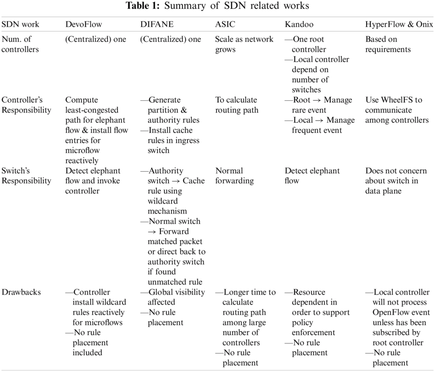
Based on Tab. 1 above, it clearly shows that the SDN work that offload controller’s workload do not optimize network bandwidth. Therefore, we aim to contrive an approach that can reduce controller’s workload and optimizing network bandwidth by imposing rule placement on elephant flows.
The proposed mechanism is emulated using Mininet through simple grid network topology consisting four (4) switches with one host as depicted in Fig. 7.
The brief processes that take place in the flow management mechanism in Fig. 8 are as follows:-
1. Elephant flow is generated via iPerf
2. When flows are transmitted by end device or pass via the switch, the switch with embedded sFlow agent will collect traffic samples and compile in UDP datagram format
3. sFlow datagram will be sent to sFlow-RT for traffic data analysis
4. sFlow-RT will work with elephant flow detection script to analyse collected packet sampling and categorise flows either elephant flow or microflow
5. Floodlight controller will perform simple forwarding or rule placement on elephant flow depending on type of elephant flow whereas data plane switches will forward micro flows to the destination point.

Figure 7: Network topology of proposed mechanism

Figure 8: Flow management mechanism
Fig. 9 depicts the elephant flow detection process. sFlow-RT will invoke elephant flow detection script which is REST application to classify flows based on pre-defined threshold. Otherwise, sFlow-RT will label the incoming flows as micro flow. Elephant flow detection script uses HTTP methods for RESTful services, i.e., GET, POST, PUT and DELETE to retrieve and analyse flows. First, the script will use HTTP-PUT to filter ingress flow, excluding discarded packets for the top ten largest flows. Second, the script will update the pre-defined flow threshold based on the current NIC bandwidth via HTTP-PUT. Then, the script will monitor the traffic retrieved via HTTP-GET in every 1000 ms interval and retrieve the top ten largest flows in the interval of 20 s.

Figure 9: Elephant flow detection flow chart
3.2 Elephant Flow Management Process
Based on Fig. 10, elephant flow will be forwarded by a controller via reactive routing whereby the controller will perform simple forwarding to re-route elephant flow to alleviate network workload and at the same time utilise alternate path whereas rule placement manages abnormal elephant flows such as FTP and RTSP flows in-conjunction with security policy.

Figure 10: Elephant flow management process
Rule placement transforms security policy into the list of forwarding rules to block potential services that might consume large link bandwidth such as FTP and RTSP. When sFlow detect large flow, it will classify the flow as elephant flow and immediately notify controller by installing a temporary flow entry indicating switch Datapath ID (DPID) and destination IP address and sent as a packet-in message to the controller. When controller received the packet-in, the controller will then determine the type of service by getting source port of the flow and assign a new path. The controller will then block the ports based on specific services for a default path. This approach is to leverage network bandwidth.
3.4 Micro Flow Management Process
Fig. 11 describes the microflow handling process. The topology example in Fig. 12 shows that microflow, which labelled as red line, between Host-1 to Host-3 involve Switch-1 and Switch-2.

Figure 11: Micro flow management process

Figure 12: Micro flow
Round-robin pairing algorithm will use ports from Switch-1 and Switch-2 to identify output ports and these output ports will become the action for wildcard entries in both switches. To uniquely identify each wildcard entry, the destination IP address would be extracted from the incoming flow and added to wildcard entry. Consecutive microflows will be matched against the existing wildcard entry and new microflows will be assigned new output ports. Fig. 13 shows round-robin pairing algorithm in assigning output ports to incoming microflows.

Figure 13: Round-robin pairing algorithm
The data plane switches will assign output ports in round-robin pairing algorithm for different microflows to reduce controller’s overhead by minimising the number of packet-in sent to the controller that used to request new flow entries. The round-robin pairing will get sets of ports to be assigned as output ports for respective wildcard entries in switches.
The round-robin pairing works by getting ports for two switches. Number of rounds to perform port pairing is halved of the total number of ports for both switches. Two sets of ports will perform the pairing as a result of splitting total ports for both switches into halved. Before performing ports pairing, the second set of ports will be inverted and then paired with the first set of ports. At last, each round will have several paired ports. Switches will handle the packet forwarding independently only for microflow without the controller to avoid flow setup between controller and the data plane switches.
Moreover, sFlow's REST API also enables metrics-based customisation to filter inbound or outbound flows. Flows can be filtered according to IP source, destination address, input port, output port, flow direction and etc. If the analysed flow is higher than the defined threshold, then sFlow-RT will regard the flow as elephant flow and trigger as event before notifying the controller. The controller will then re-route elephant flows to alternate path via reactive routing. The purpose of re-routing elephant flows is to alleviate link bandwidth between switches in the default path. For flows that are lower than the threshold, it will be regarded as microflow. Microflow then will be forwarded by switches without controller's involvement.

Figure 14: Elephant flow mitigation for single TCP traffic
Fig. 14 shows elephant flow mitigation for single TCP flow after sFlow-RT detected elephant flow at switch-4. Before mitigation, elephant flow detected on switch-4 is exceeding flow threshold, consuming high bandwidth between switch-4 and hosts and utilising all available network resources as the path was assigned by the controller using Dijkstra’s algorithm. However, the controller does not account for bandwidth competition between flows which has resulted in link congestion between switch-1 and switch-3 even when an alternate path is available. The link between switch-1 and switch-2 was underutilised. However, the elephant flow mitigation is expected to reduce bandwidth competition between flows that were sharing the same path and conserve the processing power of switches. During the mitigation process, time taken for controller to install flow entries and switches to forward flows were 6 s, which is between 53 s and 59 s as shown in Fig. 15.

Figure 15: Single TCP flow: delay in re-routing elephant flow
This is due to the limited processing power of Open-vSwitch (OVS). After mitigation, it is expected that subsequent flows will be lesser than the flow threshold. Default path has been switched to an alternate path that includes switch-1-port3, switch-2-port2 and switch-4-port1, which is labelled in a yellow line as depicted in Fig. 14. Default path's link bandwidth usage has dropped below 1 Gbps, that is the flow threshold, which means TCP flow no longer need to compete for bandwidth with the detected elephant flow in default path as both elephant flow and TCP flow able to utilise available bandwidth in two different paths. The mechanism helps to alleviate congested link, thus increases the data throughput.
Fig. 16 shows that without re-routing the elephant flow, the elephant flow will be competing for network resources like link bandwidth with other TCP flows. Furthermore, default OpenFlow architecture does not utilise alternate path to accommodate other flows that share the same path. As a result, the current path's bandwidth utilisation exceeds 1 Gbps and causes link congestion between switch-4 and source host. After re-routing elephant flows, Fig. 17 shows that the link bandwidth usage for default path has been reduced significantly.

Figure 16: Elephant flow without mitigation for two TCP flows

Figure 17: Elephant flow mitigation for two TCP flows
However, there is a sudden hike in bandwidth usage by switch-1-eth2 between 67 s and 73 s, which is the path for Host-2 to Host-1 traffic, as there is no traffic between Host-4 and Host-1 that originally passes through switch-3 and waits for new flow entries so that detected elephant flow will be re-routed and pass through switch-2. Furthermore, the mechanism does not account for subsequent elephant flow mitigation. The delay for re-routing elephant flows in two TCP traffic is 6 s as depicted in Fig. 18 but traffics between Host-2 to Host-1 remain unaffected as shown in Fig. 19. The possible reason for the delay along new path is Open vSwitch, which has lower processing power.

Figure 18: Two TCP flow: delay in re-routing elephant flows

Figure 19: Delay in re-routing elephant flows for TCP flow
Without rule placement taking place, the average throughput for TCP path is 1.639 Gbps, and the average total transfer is 195.4 GB as shown in Figs. 20 and 21.

Figure 20: Throughput on TCP path

Figure 21: Total transfer on TCP path
After implementation of rule placement, the average throughput for TCP path has an increase of 3.906 Gbps or 238%, whereas the average total transfer has increased from 195.4 to 656 GB or 238% increase. Without rule placement, both TCP flow and RTP video streaming flow were sharing the same path which results in link bandwidth competition. After RTP video stream being re-routed via rule placement, normal TCP path can utilise available bandwidth. Therefore, rule placement has alleviated link bandwidth.
Fig. 22 shows the first ping and average RTT for single ICMP ping traffic. Reactive flow insertion of microflow by controller has higher first ping, which required 138 ms more compared with multipath wildcard routing by the data plane switches without invoking the controller as expected. Reactive flow insertion causes higher first ping because the controller needs to learn topology by sending Link-Layer Discovery Protocol (LLDP) packets to all switches and switch will respond LLDP packets by sending packet-in message back to the controller. The controller will instruct the requesting switch to send Address Resolution Protocol (ARP) message to all neighbouring switches by flooding all ports and waiting for ARP-reply from the destination host. This process will take more time which resulted in higher round-trip time and first ping. However, there is a small difference in average round-trip time between reactive flow insertion and multipath routing that is 1 s.

Figure 22: First ping and average round-trip time for single ICMP traffic
For two ICMP traffics, it showed more signs of multipath wildcard routing as each host can perform flow forwarding faster than the controller. In Figs. 23 and 24, host-1 act as the server whereas host-2 and host-3 act as the client. In this scenario, both host-2 and host-3 will send ICMP ping traffic to host-1 simultaneously.

Figure 23: First ping response time for two ICMP traffic
Both Figs. 22 and 23 shows a higher first ping for controller-managed microflow regardless of the number of flows because the controller will flood all switches to determine destination host and then calculate the shortest path which will later be installed in switches along the shortest path. Unlike multipath wildcard routing, switches will perform round-robin pairing on assigning output ports for different incoming flows. As a result, the switch can forward microflow by itself and able to manage flows more quickly. Furthermore, the time for the first ping by multipath wildcard routing was so insignificant that it was almost 100 ms faster than default routing by the controller.

Figure 24: Average round-trip time for two ICMP traffic
Figs. 25 and 26 illustrated average throughput and average transfer for single TCP traffic respectively. There are three attempts to carry out the tests as one attempt might not be sufficient to determine the actual throughput whereby the first test would require more time to initialise Java Virtual Machine in order to allocate memory for the Floodlight controller. Multipath wildcard routing has produced higher throughput and allowed higher transfer capacity compared to default routing done by the controller. Since the controller will flood all ports to learn the whole network topology, it will consume more time to handle flows on a larger scale of the network. Results showed that 1% increase in throughput and total transfer for single TCP traffic.

Figure 25: Average throughput for single TCP traffic
As for two TCP traffic, multipath wildcard routing showed a higher throughput and increase in average total transfer for both host-1-to-host-3 and host-1-to-host-4 traffics as compared with default routing done by the controller. Fig. 27 showed that there is an increase in average total transfer between host-1 and host-4 for multipath wildcard routing, which is 12% higher than the controller’s routing whereas total transfer between host-1 and host-3 have higher transfer size as well, which is 11% higher than the controller’s routing. Meanwhile, multipath wildcard routing also showed higher throughput between hosts, i.e., host-1-to-host-3 and host-1-to-host-4, which are 11% higher throughput compared to controller’s routing as shown in Fig. 28.

Figure 26: Average transfer for single TCP traffic

Figure 27: Average transfer for two TCP traffic

Figure 28: Average throughput for two TCP traffic
Fig. 29 shows that the controller should handle more packet-in if microflow managed by controller compared with multipath wildcard routing. When the number of flows increase, number of packet-in messages sent to the controller would be more if the controller handled microflows. As a result, the controller received 48% more packet-in messages in two TCP traffic as compared with 23% more packet-in messages in single TCP traffic.

Figure 29: Number of packet-in received by controller
OpenFlow simplifies whole network management by separating network policies from realisation and its external controller like Floodlight has great functionality such as firewall and load balancing, but they are still unable to solve the current dilemma such as controller’s overhead and rule placement issues. In particular, traditional OpenFlow requires the controller to handle all flows regardless of importance and flow size. Thus, the proposed mechanism used an efficient packet-sampling tool such as sFlow and sFlow-RT as packet-analysing engines to segregate flows into two categories, such as elephant flow and microflow via elephant flow detection script that is invoked in SDN application layer. The mechanism will re-route detected elephant flow into an alternate path via reactive routing to alleviate link bandwidth below the pre-defined threshold value; however, there is some loss of traffic in between re-routed elephant traffic as a result of the delay between controller inserting new flow entries into switches and forwarding done by switches. The possible reason for this delay is that the new path limits the processing power of OVS switch. Moreover, rule placement has contributed higher throughput and total transfer for TCP path after re-routing RTP video streams that shared the same path as TCP flows into the alternate path. This step can ensure that the security policy is respected besides utilising other unused links. Although reactive routing in the proposed mechanism causes some delay in processing elephant flow and only able to assign paths in fixed topology, it still able to reduce link bandwidth usage.
Conversely, the mechanism achieves better throughput and total transfer size in handling microflows and showed greater significance in two TCP traffic rather than single TCP traffic, which are 11% and 12% higher than the controller’s default routing in two TCP traffics as compared with the centralised OpenFlow controller. First ping response time for multipath wildcard routing in single ICMP traffic showed great difference as compared to two ICMP traffic where first ping response time in single ICMP traffic for multipath wildcard routing was 100 ms faster than controller’s default routing. In terms of workload, multipath wildcard routing offloads controller by 48% less packet-in messages in two TCP traffics and 23% less packet-in messages in single TCP traffic.
Traditional OpenFlow does not implement rule placement on flow with specific services like RTSP. This flow can be crucial in terms of link bandwidth allocation and can be managed by rule placement. Although rule placement might possess similar functionality with a common firewall in which both apply security rules based on access control lists, however, traditional firewall device cannot be disregarded because firewall is a more sophisticated device with higher processing capacity, designed to filter packets and block unwanted traffic more efficiently. Hence, rule placement will only be served as an additional security mechanism to help firewall and IDS to enforce security policies. The proposed mechanism reduces the need for invoking controller for insignificant flow or microflow and implements high-level security policy by transforming them into a list of forwarding rules.
In the future, we intent to test our implementation in a bigger network topology that has more OpenFlow switches with more network traffics.
Funding Statement: The authors received no specific funding for this study.
Conflicts of Interest: The authors declare that they have no conflicts of interest to report regarding the present study.
1. R. H. Jhaveri, R. Tan and S. V. Ramani, “Real-time QoS-aware routing scheme in SDN-based robotic cyber-physical systems,” in 2019 IEEE 5th Int. Conf. on Mechatronics System and Robots, Singapore, pp. 18–23, 2019. [Google Scholar]
2. M. H. Abidi, H. Alkhalefah, K. Moiduddin, M. Alazab, M. K. Mohammed et al., “Optimal 5G network slicing using machine learning and deep learning concepts,” Computer Standards & Interfaces, vol. 76, no. 1, pp. 103518, 2021. [Google Scholar]
3. M. I. Zahoor, Z. Dou, S. B. H. Shah, I. U. Khan, S. Ayub et al., “Pilot decontamination using asynchronous fractional pilot scheduling in massive MIMO systems,” Sensors, vol. 20, no. 21, pp. 6213, 2020. [Google Scholar]
4. A. R. Curtis, J. C. Mogul, J. Tourrilhes, P. Yalagandula, P. Sharma et al., “DevoFlow: Scaling flow management for high-performance networks,” in Proc. of the ACM SIGCOMM, 2011 Conf., Toronto, Ontario, Canada, pp. 254–265, 2011. [Google Scholar]
5. E. B. H. Tan and Y. W. Chong, “An optimized flow management mechanism in OpenFlow network,” in 2017 Int. Conf. on Information Networking, Da Nang, Vietnam, IEEE, pp. 143–147, 2017. [Google Scholar]
6. S. U. Rehman, W. Song and M. Kang, “Network-wide traffic visibility in OF@TEIN SDN testbed using sFlow,” in 16th Asia-Pacific Network Operations and Management Symp., Hsinchu, Taiwan, pp. 1–6, 2014. [Google Scholar]
7. sFlow-RT@ ONLINE, [Online]. Available: http://www.inmon.com/products/sFlow-RT.php. [Google Scholar]
8. J. R. Correa and M. X. Goemans, “Improved bounds on nonblocking 3-stage clos network,” SIAM Journal on Computing, vol. 37, no. 3, pp. 870–894, 2007. [Google Scholar]
9. T. Erlebach and M. Ruegg, “Optimal bandwidth reservation in hose-model VPNs with multi-path routing,” in IEEE INFOCOM 2004, Hong Kong, China, vol. 4, pp. 2275–2282, 2004. [Google Scholar]
10. M. Kodialam, T. V. Lakshman and S. Sengupta, “Maximum throughput routing of traffic in the hose model,” in Proc. IEEE INFOCOM 2006. 25TH IEEE Int. Conf. on Computer Communications, Barcelona, Spain, pp. 1–11, 2006. [Google Scholar]
11. M. Yu, J. Rexford, M. J. Freedman and J. Wang, “Scalable flow-based networking with DIFANE,” ACM SIGCOMM Computer Communication Review, vol. 40, no. 4, pp. 351–362, 2010. [Google Scholar]
12. S. Y. Hassas and Y. Ganjali, “Kandoo: A framework for efficient and scalable offloading of control applications,” in Proc. of the First Workshop on Hot Topics in Software Defined Networks, Helsinki, Finland, pp. 19–24, 2012. [Google Scholar]
13. P. Lin, J. Bi and H. Hu, “ASIC: An architecture for scalable intra-domain control in OpenFlow,” in Proc. of the 7th Int. Conf. on Future Internet Technologies, Seoul, Korea, pp. 21–26, 2012. [Google Scholar]
14. A. Tootoonchian and Y. Ganjali, “Hyperflow: A distributed control plane for openflow,” in Proc. of the 2010 Internet Network Management Conf. on Research on Enterprise Networking, San Jose, USA, vol. 3, 2010. [Google Scholar]
15. T. Koponen, M. Casado, N. Gude, J. Stribling, L. Poutievski et al., “Onix: A distributed control platform for large-scale production networks,” in OSDI, vol. 10, pp. 1–6, 2010. [Google Scholar]
16. J. Petrovic, “Using memcached for data distribution in industrial environment,” in Third Int. Conf. on Systems (icons 2008Cancun, Mexico, pp. 368–372, 2008. [Google Scholar]
17. J. Stribling, Y. Sovran, I. Zhang, X. Pretzer, J. Li et al., “Flexible, wide-area storage for distributed systems with WheelFS,” in NSDI, vol. 9, pp. 43–58, 2009. [Google Scholar]
18. A. Abdelaziz, T. F. Ang, A. Gani, U. Garba, S. Khan et al., “Distributed controller clustering in software defined networks,” PloS One, vol. 12, no. 4, pp. e0174715, 2017. [Google Scholar]
19. X. Nguyen, D. Saucez, C. Barakat and T. Turletti, “Rules placement problem in OpenFlow networks: A survey,” IEEE Communications Surveys & Tutorials, vol. 18, no. 2, pp. 1273–1286, 2015. [Google Scholar]
20. X. Nguyen, D. Saucez, C. Barakat and T. Turletti, “Optimizing rules placement in openflow networks: Trading routing for better efficiency,” in Proc. of the Third Workshop on Hot Topics in Software Defined Networking, Chicago, Illinois, USA, pp. 127–132, 2014. [Google Scholar]
 | This work is licensed under a Creative Commons Attribution 4.0 International License, which permits unrestricted use, distribution, and reproduction in any medium, provided the original work is properly cited. |