DOI:10.32604/cmc.2022.019769
| Computers, Materials & Continua DOI:10.32604/cmc.2022.019769 | |
| Article |
Reconfigurable Pattern Patch Antenna for Mid-Band 5G: A Review
1Department of Electrical Engineering, Politeknik Sultan Abdul Halim Mu'adzam Shah, Jitra, 06000, Malaysia
2Advanced Communication Engineering (ACE), Centre of Excellence, Universiti Malaysia Perlis. Faculty of Electronic Engineering Technology, Universiti Malaysia Perlis, Pauh Putra, 02600, Malaysia
3College of Computer Engineering and Sciences, Prince Sattam Bin Abdulaziz University, P.O. Box 151, Alkharj, 11942, Saudi Arabia
4Faculty of Electrical and Electronic Engineering, Universiti Tun Hussein Onn Malaysia, Parit Raja, 86400, Malaysia
5School of Engineering, University of Glasgow, Glasgow, G12 8QQ, U.K
*Corresponding Author: Muzammil Jusoh. Email: muzammil@unimap.edu.my
Received: 25 April 2021; Accepted: 06 June 2021
Abstract: New requirements in communication technologies make it imperative to rehash conventional features such as reconfigurable antennas to adapt with the future adaptability advancements. This paper presents a comprehensive review of reconfigurable antennas, specifically in terms of radiation patterns for adaptation in the upcoming Fifth Generation (5G) New Radio frequency bands. They represent the key of antenna technology for materializing a high rate transmission, increased spectral and energy efficiency, reduced interference, and improved the beam steering and beam shaping, thereby land a great promise for planar antennas to boost the mid-band 5G. This review begins with an overview of the underlying principals in reconfiguring radiation patterns, followed by the presentations of the implemented innovative antenna topologies to suit particular advanced features. The various adaptation techniques of radiation pattern reconfigurable planar antennas and the understanding of its antenna design approaches has been investigated for its radiation pattern enhancement. A variety of design configurations have also been critically studied for their compatibilities to be operated in the mid-band communication systems. The review provides new insights on pattern reconfigurable antenna where such antennas are categorized as beam steering antenna and beam shaping antennas where the operation modes and purposes are clearly investigated. The review also revealed that for mid-band 5G communication, the commonly used electronic switching such as PIN diodes have sufficient isolation loss to provide the required beam performance.
Keywords: 5G mid-band pattern antenna; reconfigurable antenna; phased array antenna; antenna and propagation
Reconfigurable antennas can be either reconfigured in terms of operating frequency, polarization, or radiation pattern [1]. Due to the 5G technology demand in beam steering and beam shaping, radiation pattern reconfigurable antennas are vital and being researched extensively. In 5G technology, the mid-band frequencies that defined from 1 to 6 GHz [2,3], is being widely used in many wireless technologies in particular, and the Internet of Things applications. Using the mid-band frequencies, low power consumption can be maintained when communicating within a short range of network devices [2]. However, the effectiveness of such systems is dependent on the level of multipath and interference [4,5]. Thus, reconfiguration of the radiation patterns of antennas will enable the enhancement of signal strength and transmission efficiency [6].
Pattern reconfiguration antennas are one of the key technologies for modern telecommunication application. Pattern reconfigurability is significantly important with the ability to change the current source distribution on the antenna structure by performing the radiated energy as the beam to the dedicated or specific directions that eventually helps to improve the data throughput of the communication [7]. The reconfigurable pattern antenna could avoid noise sources by directing null toward interference and radiate the main beam to the desired direction for better coverage improvement. This antenna has advantages with its compact size, small power consumption, and increasing functionality to resolve the burden on today's transmission systems within of confined volume place. The 4G suffers from congestion and cannot support the higher data rate demand by users due their limitation of their frequencies spectrum [8]. The mid-band with faster and high availability to lead the industry to point up their potential and to deliver functionality to smooth the transformation in 5G journey [9]. The mid-band range under 6 GHz makes it not similar with mmWave frequency range above 24 GHz even both are called ‘5G’. Mid-band range is a greater choice to exploit the existing network backbones accommodation when it faster than previous 4G technology. Even the latency is not as good as mmWave, the mid-band able to cover larger geographical areas compared to mmWave who struggle due their limitation that suited in only small specific target area. Although this review focuses on the radiation pattern reconfigurable for 5G mid-band communication, the existing pattern reconfigurable antennas that designed within this frequency range are also reviewed. It is because similar reconfiguration techniques are appropriate for mid-band frequency range as the material specification and component specification for such designs are similar.
Many techniques have been proposed in literature to reconfigure the antennas [10–14] that can be mainly categorized as either electronic, optical, mechanical and material. Besides needing to be low in complexity and effectiveness in implementing reconfiguration techniques, the antenna topology for such antennas needs to have a compactness feature. The large size of a wire antenna had been a constraint to be best nominee for high frequency applications [15]. Planar antennas can be fabricated with ease and designed to operate from frequencies as low as 100 MHz [16] to tens of GHz [17–19]. It is also important that such reconfigurable antennas are able to achieve higher gain and wide bandwidths at the higher frequencies [20,21]. Ideally, such compact pattern reconfigurable antenna must be designed to achieve accurate beam reconfiguration and gain improvements in the required directions. The performance of reconfigurable antennas (gain, impedance bandwidth, and the beam's capability for steering and shaping) mainly relies on the method being used. The other crucial contributing factors are the types of substrate, the feeding technique being used and the number of switches deployed.
This work aims to provide a comprehensive review of pattern reconfigurable planar antenna designs operating in the mid-band frequency ranges. To the best of our knowledge, this is one of the first reviews of its kind related to radiation-reconfigurable antennas specifically focused on mid-band antennas. The review is organized as follows. The first section of this review will present the common reconfiguration techniques such as electronic, optical, mechanical and material changes. The second section will discuss on planar reconfigurable antenna topologies which are printed monopole, printed dipole, printed slot and patch antennas. A detailed explanation of beam steering and beam shaping on design improvement will be discussed in the last sections.
The radiation pattern performance of the reconfigurable patch antenna depends on the technique and the types of reconfigurable mechanisms used. There still have been challenges in modifying the antenna structure to apply different reconfiguration techniques [22,23]. In reconfigurable antenna design many factors need to be considered, such as how to achieve a good gain, better in efficiency, stability in reflection coefficient, radiation pattern directivity, beam shaping capability and good impedance matching at all states of antenna's operation. Therefore, it has been a challenging aspect for antenna designers to achieve and maintain efficiency and effectiveness of the solution when integrating the reconfigurable mechanism into a complete system.
As visualized in Fig. 1, there are four key techniques applied by researchers to achieve reconfigurability and improvement in various scenarios. The characteristics and types of the switching techniques used drastically affect the response of the reconfigurable antenna. Most of these techniques able to perform the radiation pattern reconfiguration with their ability to control the surface current distribution by modification of their EM or material properties.
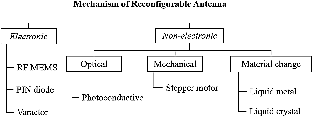
Figure 1: Overview of techniques to achieve reconfiguration
The following subsections will discuss the advantages and disadvantages of studying each mechanism type in reconfigurable antenna development.
2.1 Electronic Reconfiguring Methods
Electronics switching was the popular technique that has been recently chosen in [24–26] as reconfiguration mechanism. The electronic switch that most commonly used for reconfigurable antenna is PIN Diode. The employment of direct shorting with and capacitive over coupling feeding leads to the directional of the beam pattern. In [27], the study of a reconfigurable antenna has been carried out by full-wave analysis to propose the small size comparable antenna that can switch diversity of radiation pattern either boresight or conical pattern electrically. The freedom of capability to optimize the gain for dual pattern patch modes is achieved by locating the PIN diodes on the ground plane rather than the patch layer. The work in [28] had performed a radiation pattern of parasitic pixel patch antenna structure with 52 PIN diode switches located between the edge of pixels to achieve a different pattern reconfigurable shape for operating at frequency 5.7 GHz. Although the used of large active elements for reconfigurable contributed to good isolation, it however has increased the cost and biasing complexity [29]. Since the discussion is focused on 5G, the behavior of PIN diodes when operates at mm-Wave frequencies should be clearly understood. It should be noted that, the isolation loss and insertion loss of the PIN diodes could determine the performance of the beam steering in reconfigurable antenna. A few works were reported on comparing the performance of beam steering with PIN diodes at similar operating frequency [30] and the performance of the beam steering when a similar PIN diode is used for different distinct frequencies [31]. From [30] it can be noticed that, the beam steering tilt angle is dropped when a low isolation loss PIN diode is used compared with a high isolation loss PIN diode. On the other hand, the tilt angle degradation and deployment challenges are known for the antenna design operating above 20 GHz frequency. Therefore, for mid-band 5G frequencies, the performance degradation could be expected only for the design adopting low isolation PIN diodes that operates above 5 GHz.
Varactor diode is the other nest of initiating reconfigurability. A notable work [32] shows the use of varactor for achieved the phase control and reached the ±23° of beam scanning. The other design in [33] stated that the varactor diodes provided a dynamic reconfiguration capability but unfortunately, it suffers from nonlinearity, low dynamic range and biasing complexity. Some other type that often used is RF MEMS. Work [34] reported that 8 switches are located in the slot region of the radiating structure to achieve reconfiguration. The work has shown that this low-profile switching type does not need additional biasing or added space for feeding network, and thus it easy to unite with other circuit components. However, the deficiency of MEMS is less reliable and costly as opposed to PIN diodes [35].
2.2 Non-Electronic Reconfiguring Methods
Unlike electronic reconfiguration, the optical technique has constraints for lossy behavior and complex activation mechanisms, while the mechanical technique confronts a slow response [36–39], but the best are these two tend to perform without require biasing lines. The material change technique exhibits low profile and lighter weight but, unfortunately, had limited application [40,41]. These will be discussed in this subsection.
Optical switching consists of transparent material to reconfigure the antenna. This technique is a good option for deflected electromagnetic perturbations such as in [42] that used a two photoconductive switch illuminated using 808 nm laser. The reconfiguration cannot be done without impedance alteration and be resolved by reducing the length of the upper slot T-shape to 3.35 mm and increasing the capacitance to 2.2 pF. Furthermore, in work [43], they used the optical switch to reconfigure the beam by filtering unwanted interference signals to obtain maximum gain.
Mechanical steering is the ideal means of beam steering since it does not incur insertion losses and the antenna performance is not degraded at any point. The mechanical technique involves with physical turning of the antenna to face the direction of interest [7], where mechanical steering is often performed by means of an electric motor. However, rotating mechanisms are prone to mechanical failure due to fatigue and wearing of moving parts [44]. Another type of reconfiguration such as stepper motor is used to mechanically control the antenna rotation [45]. In such a method, the motor is placed behind the antenna to improve the stepper motor's synergy and the accuracy of beam direction. Despite demonstrating a diverse configuration due to its higher degree of freedom in achieving reconfigurable broadside and end fire patterns, factors such as the antenna size, weight, and control voltage make the mechanical solution difficult for implementation. Furthermore, the slow speed of steering is the major disadvantage of such mechanical switching compared to electronic switching methods [46,47].
Recently, liquid metals created popular intention among researchers in reconfigurable antennas [48,49] by offering a greater tuning range and the possibility to minimize nonlinear distortion created by semiconductor devices [50]. As presented in [51], Eutectic Gallium Indium has been used as liquid metal and it can be tuned within the capillaries by applying DC voltages to individual arm to provide liquid displacement mechanism. The liquid displacement could be easily performed and it does not require mechanical pumps to produce different radiation patterns. Comparison with other semiconductor devices indicates that such liquid displacement can achieve radiation efficiencies higher than 90%.
Another approach in material change is in printed three-element Yagi Uda antenna, in which the two parasitic elements have slots in the middle [52]. Six moveable metal poles have been filled in the microfluidic channels attached to the surface three radiating arms of the antenna. The ON and OFF condition was depended on moving liquid metal poles and the electrical lengths. The studied achieved to work at 5 modes and gain 7.3 dBi.
The best possible reconfiguration technique is the one that is more fulfilling to the restraints of the application in which the antenna is designed. The researcher should consider to minimizing the antenna design complexity and reconfiguration of biasing devices by keeping the optimum desired performance. Apart from easy to embed on the antenna structure, the use of electronic switching components such as PIN diode gives the advantages of good isolation, low-loss property, fast configuration, and eventually help to reduce the cost and power consumption. For the next sections, the radiation pattern reconfiguration will be discussed in more detail, including the various techniques applied for its enhancement.
3 Reconfigurable Antenna Topologies
Radiation pattern reconfigurable antennas are considered the best candidate to control the power pattern and the directivity gain [53–55]. Various types of antennas have been studied in the literature for 5G mid-band operation [56–58]. As presented in Fig. 2, three printed types of reconfigurable antennas are regularly used to deliver performance in many scenarios.
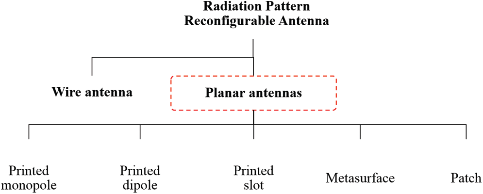
Figure 2: Types of radiation pattern reconfigurable antenna
Wire monopole array antennas [59] have characteristic which are suitable for operating in low and medium frequency, wide in bandwidth and featured with the omnidirectional radiation pattern. Compared to the traditional method, the printed type antenna used the metallic plate instead of wire for radiated the energy signal [60]. Others low profile monopole antennas were also discussed in [57,61,62]. Fig. 3 shows that various printed monopoles designed like monopole antenna array [63], folded monopoles antenna [64] and printed inverted-F [65] that achieved a stable radiation pattern in each operation state in their microwave frequency application. In [63], the monopole antenna surrounded by four parasitic elements has connected to coaxial fed with a 45° angle interval. The radiation elevation angle achieved 60° with peak gain larger than 7 dBi. The study succeeded in improving the impedance property and phase compensated by adopting a shorter parasitic strip between a monopole and a longer strip. Eight PIN diodes in that parasitic pairs were used to control the monopole radiation at eight different beams in the azimuth plane. The other study in [64] designed four folded monopoles with a windmill-shape and a ground plane fed by a coaxial probe. The study achieved four steering modes within 30° to 300° at the azimuth plane with a stable gain at 3.9 GHz. This study also exhibits an operational wide bandwidth regardless of the switching states. The symmetrical structure of the antenna contributed to the good stability in terms of radiation pattern reconfiguration. The study in [65] has shown that the printed inverted-F with the partial ground had matching and pattern optimize by altering the stub's length and width. This design provides orthogonal radiation patterns using only one PIN diode for reconfigurability and achieved HPBW beamwidth of 226° and 118.5°.
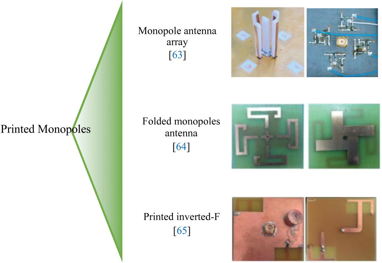
Figure 3: Various of printed monopoles
Several types of printed dipole antenna are investigated and analysed based on to their performances. Fig. 4 shows previous designs using printed dipole elements that were used to attain improvement in various scenarios. Ben Trad et al. [66] proposed a planar printed dipole antenna based on the classification on the Yagi Uda concept [67]. This work combined two different sizes of elementary dipoles back to back acted as reflectors and directors. The antenna has printed on an Arlon CuClad217 substrate that having low circuit losses at higher frequency. By using Four Skyworks-SMP 1320−079LF diodes, this work achieved the dual beams and single beam patterns in both −x and +x directions in three modes with the gain reached between 5.37 to 8.12 dBi. The tilted beam directions have no stated but the achieved properties have suit for mid-band communication application. In [68], presented the printed λ/2 dipole with two twisted loading elements on the upper surface. The studied had discovered the two metallic square elements that had located below the dipole surface contributed to the achievement of directional radiation pattern in both ϕ = 0° and ϕ = 90° planes with gain of 3.98 to 6.4 dBi respectively. However, the dimension changes on dipole or parasitic elements might affect to the S11 performances.
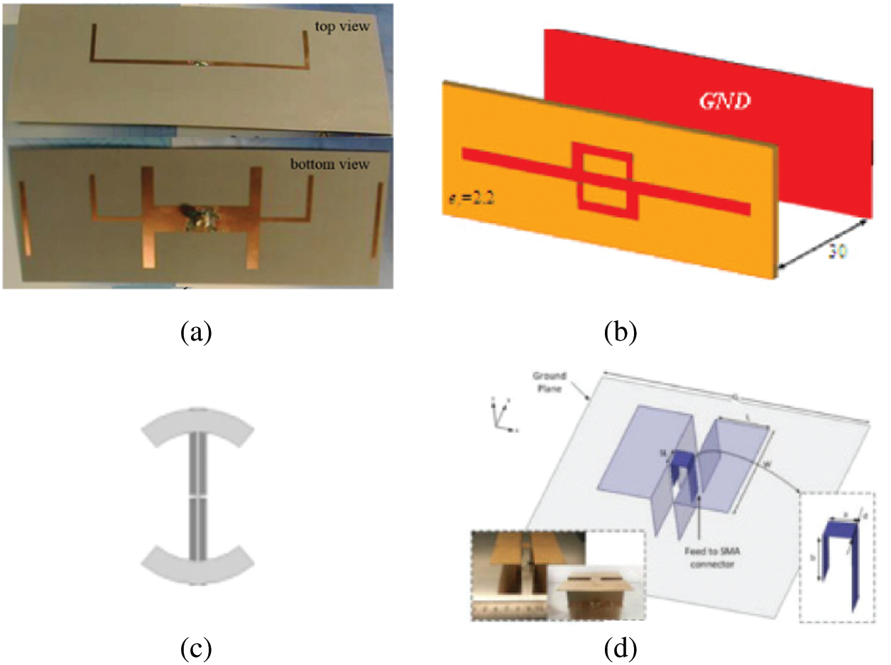
Figure 4: Dipole elements (a) [66] (b) [68] (c) [69] (d) [70]
The other design in [69] combined a pair of strips driven elements with a pair of Egypt Axe Dipole elements. The design had achieved the reconfiguration of the omnidirectional radiation pattern by integrated the PIN diodes into the driven element. In other research [70], Zeng et al. designed a half-wavelength electric dipole antenna with a Γ-shaped strip feedline. The defected ground structure had applied to this simple antenna capable of performing unidirectional radiation pattern with a low back lobe that improved at frequency ranges from 1.38 to 3.5 GHz with gain up to 8.3 dBi. However, some degrades of front-to-back ratios and cross-polarization levels have been reported compared to previously designed in [71,72]. The other proposed work in [46] has achieved the 3 different directions of ±90° at 3 different frequencies by combining the Vivaldi antennas into a single radiated structure. Even the antenna size is quite large, but it was useful for multipath fading problems. Furthermore, the dipole type was a good approached where it required an isotropic pattern for the communication system. Many cases of the printed dipole antenna required the feeding mechanism to function as balun effects to remedy asymmetrical distortion [73] effected by coaxial fed unbalance feeder due to achieve the effective radiation pattern.
Instead of having the characteristics of enhancing the frequency shifting, the printed slot did well on beam pattern reconfigurability and these designed illustrated in Fig. 5. The previous work in [74] employed on Taconic RF35 material and used the 3 switches along each of four slits for obtaining the pattern reconfiguration. By manipulated the phase of upper and lower slits at the ground plane, this work had achieved three directions beam at −15°, 0° and +15° at all frequency bands 1.82, 1.93 and 2.10 GHz. However, using the 14 BAR50–02V PIN diodes increased the complexity and the system's insertion losses. The other antenna in [75] has complexity in designing combination elements of the perturbed rhombic slot with truncated circular radiator and C shaped parasitic. Using of FR4 material, the result achieved ±30° of tilted beam and also worked with others’ capability in frequency and polarization configured by BAR 64-0W pin diodes.
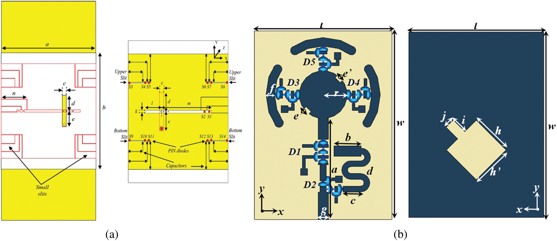
Figure 5: Printed slot antennas (a) Front and back view [74] (b) Front and rear view [75]
The metasurface antennas have made of interesting applications with the introduction of unit cells structures and their unique electromagnetic properties [76,77]. Fig. 6 shows several metasurface antennas that can be classified into three types of metasurface structure, active metasurface and non-uniform metasurface. The study in [78] shown the reconfigurable metasurface antenna composed of uniform distribution double-split square rings that are loaded with PIN diodes to serve as both a reflector and director when the diodes are respectively in forward biases for achieving −z direction and reverse biases for the +z direction. Such antenna fabricated on FR-4 substrates is yet managed to obtain a good impedance matching in both diode states and has gain of approximately 6 dBi at 2.45 GHz. Another study in [79] showed that an active metasurface with a patch antenna had capability of achieving 10° beam steering at ϕ = 90° and gain of 6 dBi at 2.45 GHz using PIN diodes switches. The study shows that gap lengths of spilt rings significantly influence the antenna directivity and beam steering performance. On the other hand, it introduces high complexity in circuitry with the 16 PIN diodes. Research work in [80] also using the FR-4 as substrates, and the antenna succeeds in achieving gain of 7.1 dBi with operating frequency of 2.35 to 3.5 GHz. By optimizing the variation range of metasurface unit cells, the patch antenna main beam can be steered to 30° angle with HPBW of 66°.

Figure 6: Metasurface antennas (a) Metasurface [78] (b) Active metasurface [79] (c) Non-uniform metasurface [80]
Patch topology is the most common and widely used is the reconfigurable antenna. Patches used as radiating elements have a greater prospect to cater multidirectional, frequency agility, broader in bandwidth and feeding flexibility [81]. As can be seen in Fig. 7, the rectangular patch design in [82] was improved by adding two metal walls to achieve a beam shaping and multidirectional beams. The pattern reconfigurable antenna produced boresight radiation patterns that inclusive of narrow and wide beamwidth. Using 6 PIN diodes, the main beam pattern was steered in the E-plane from −51° to 54° and H-plane from −20° to 20° using the discrete switching conditions. This work also achieved 400 MHz of bandwidth deploying aperture coupled feeding technique. In another related work, [83] a fork-shaped microstrip feedline had been applied for obtaining the pattern reconfiguration using the 2 pin diodes that were inserted across the feeding line. This work achieved beam steering up to 25° angle and while managed to perform beam shaping. Although the design attained lower tilt angle, it operates in a wide bandwidth. The performance of the reconfigurable radiation pattern antenna depends on factors such as the patch shape, feeding technique and the substrate type. Apart from that, the selection of dielectric constant had also been considered to achieve antenna compactness, loosely the bound field of radiation pattern and better efficiency [84].
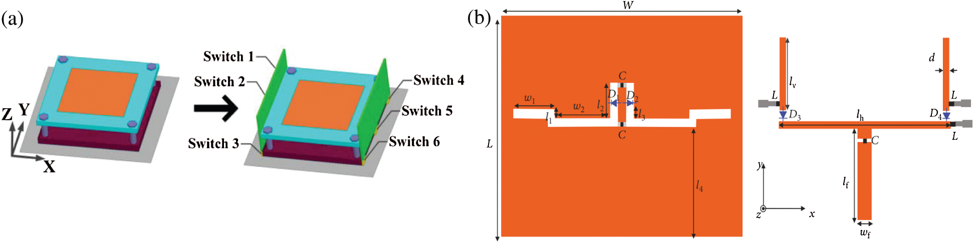
Figure 7: Patch antennas (a) Pattern reconfigurable microstrip antenna in [82] (b) Pattern-reconfigurable wideband slot antenna in [83]
The future reconfigurable antennas should be multifunctional by providing beam steering and beamwidth reconfiguration in a single antenna structure and have software-controlled/machine-learning abilities to detect and respond to different changes in their RF environment. That will make it strong potential to improve the performance of wireless communication systems. Besides, it is potential to have a hybrid antenna reconfiguration with the ability to reconfigure pattern, frequency and polarization on a single antenna structure.
4 Radiation Pattern Enhancements
The future technologies will hunt for higher reception and protection against interference in real-time. A proper pattern configuration is required in short-range frequency to improve gain. Pattern reconfiguration is generally considered as the capability of reconfiguring the beam due to attain the strongest received signal strength. The application of antenna systems for mid-band compatibility is widely dependent on the enhancement of its pattern performance. There are essential differences between the concept of beam steering and beam shaping. Beam steering can dynamically alter the phase of the input signal on radiating elements and cause the beam to change at the desired directional [85]. Beam shaping provides the freedom of 3 dB-beamwidth control in the antenna's wide beam. The beamwidth control are suitable for cellular base station applications, which require antennas of different 3 dB-beamwidth to accommodate a variety of environments [86]. Both concepts produced null or lower interference to unintended directions. As a matter of fact, some extra configuring efforts need to explore to meet the demanding of 5G technology.
A pattern reconfiguration antenna designed in [87] for user-end able to perform reconfiguration for improved signal reception, but it designed with a complex circuitry on its feeding side. Likewise, the pattern reconfigurable antennas designed in [28,88,89] managed to obtain the maximum beam tilt angle up to 40° and no result of beam shaping was reported in that works. On the other hand, the work in [90] succeeded in obtaining three beam shapes with the usage of 8 switches and just obtained a limited maximum beam tilt angle of between −17° and +14°.
From the studies it is known that significant improvements in terms of number of radiation patterns, radiation tilt angle, radiation efficiency, common operational bandwidth and adaptive beam configuration can be achieved by deploying additional elements or techniques in the antenna design. Tab. 1 illustrates the state of art for patch pattern reconfigurable techniques reported in [14,91–94] that were commonly adopted by researchers for improving the performance of pattern reconfigurable antennas. Despite these promising results, questions remain of combating to improve the above-noted performances, the pattern reconfigurable antenna suffers from other external factors as follows. In some designs, the conductor material that adopted for the patch elements together with the substrate material had been the main factor for high loss performance [95]. The effects of using reactive impedance on biasing elements of a reconfigurable antenna also influences antenna performance. Apart from this, reconfigurable antenna structures that employed with multiple feed lines with various path lengths between feeding can produce unwanted reflections of incident signals in the same frequency and degrade the radiation performance of the antenna [90]. The advanced design strategies for radiation pattern enhancement of a patch reconfigurable antennas will also be discussed intensively in the forthcoming sections.

Many approaches have been initiated in the literature where the beam control element of the reconfigurable antenna was put into the attention for the enhancement of the beam pattern performance. Tab. 2 summarizes various previous research and achievement in their features for pattern reconfigurable antennas. Some widely and newest structure designs are discussed here specifically for acknowledging the concept of beam steering.
In the previous study in [96] reported that performed the beam angle steering in a range of ±30° with 12 dB of gain by using a Taconic substrate. This low-profile antenna used 2 PIN diodes for reconfiguration with obtaining the 174 MHz bandwidth. Otherwise, the mutual impedance evolved between the driven element and parasitic element had affected the reflection coefficient of the antenna. Some approached had reported in [97] that achieved beam steering at 25° angle by used of 4 HPND 4005 RF PIN diodes for the reconfiguration mechanism that had embeds to the each of 4 parasitic elements. This design managed to get 7 dB in gain by using the Taconic substrate even though it just achieved 30 MHz in bandwidth for resonance frequency at 2.38 GHz.
In other novelty work in [88] stated the ability to reconfigure the beam at 2.5 GHz frequency. The antenna was fabricated on a Rogers RO4003 substrate. The design consists of patch antenna at driven layer and the pixels that functioned as a switched grid of small metallic patches that used at parasitic layer to provide reconfiguration capabilities cause of the coupling effect by existing radiator driven patch antenna. The antenna had combines a patch and a parasitic pixel surface consisted of 36 pixels with a reconfigurable using of 60 PIN diode (NXP BAP 64-02). This study achieved a steer beam angle within ±30° with an average 6–7 dBi. Even had a wider in 300 MHz of bandwidth, this antenna has faced the complexity of switching by using a big number of switches.
In another beam steering novelty work by Thennarasan et al. reported that achieved the steering at 5.8 GHz operating band frequency [98]. The antenna design consists of five parallel patches on a grounded Taconic dielectric substrate with a thickness of 1.6 mm and a dielectric constant (ɛr) of 2.2. The 6 HPND 4005 RF PIN diodes have been deployed at parasitic elements by connecting them to the rear ground plane using shorting pins. This antenna has improved the steering by adopt truncated technique to both left and right edges on the ground plane of the antenna. This study achieved an average peak gain of 7.5 dBi and capable to steer a beam at an elevation angle between ±50° from the broadside. Moreover, this work managed to achieve the highest degree of steering, this study performs complicity on biasing circuitry and keeping a low profile structural antenna.
A single antenna element in [99] managed beam-steering capability at broad frequency of 5.2 to 5.8 GHz with the beam steering capability of ±30° angle. This work employed the Rogers RO4003c as substrates and consists of an aperture-coupled stacked patch with six rectangular-shaped metallic pixels layer that placed above it. The 6 PIN diodes used for pixel configuration achieved maximum gain of 6.5 dBi. Similarly, another antenna in [89] also used Rogers 4003c as substrates for both driven patch and parasitic pixel layer together with the aperture coupled technique to operate from 2.4 to 2.5 GHz. Fig. 8 shows the usage of 12 PIN diodes to switch ON and OFF status in order to control the 3 × 3 pixel parasitic surface elements. The elements have the mutual coupling effect because of the radiation strength from a driven patch at the antenna. As reported, the antenna had the capability to steer in nine different modes and succeed to tilt at ±30° of elevation angle depends on the proper reactive loading. Unfortunately, by using a large number of PIN diodes issuing in manufacturing intricacy and decreasing antenna gain cause by diodes ohmic losses. However, other than the beam steering ability, leakage (interference) between two indicated nodes can be minimized in the unwanted directions and the SNR can also be maximized in the wanted direction.


Figure 8: Beam steering reconfigurable antenna in [89]. (a) Top view of reconfigurable antenna techniques to achieve reconfigurable (b) Backside of the parasitic layer (c) Simulated and measured for (θ = ±30°; ϕ = 0°, 45°, 90°, 135°) at 2.45 GHz
In [100], Chinmayarangaraj et al. demonstrated the capability of a reconfigurable antenna by obtaining the steering of θ = {−30°, 0°, 30°} for ϕ = 90° at 2.4 GHz with achieved gain in the range of 8.5 to 9 dBi. It can be seen in Fig. 9 that the ring slot metallization on the parasitic layer located the four switches for beam reconfiguration achievement. The Duroid substrate had been applied as parasitic while the other four blocks of Rogers 4003 substrate have been applied at four corners of the patch to support the parasitic layer on top.

Figure 9: (a) Schematic of patch fed pattern reconfigurable ring slot antenna (b) Reflection coefficient and (c) radiation pattern of 3 modes of operation [100]
Design in [101] consists of a single disc patch coupled to four sector elements that have been connected to four PIN diodes outside radiating elements. It can be seen in Fig. 10 that the small antenna achieved four different beams tilted at φ = {0°, 90°, 180°, 270°} for θ = 30° and 31° with gain 8 dBi. It has been observed that the symmetrical patch of the antenna structure influenced the stability for the antenna performance. Even though the reconfigurable antenna only worked at a single elevation angle, it remains great potential for point-to-point mobile communications for access on frequency 3.5 GHz.
The other study in [102] reported that the effects on the radiation pattern when altered the dimension of splits. It happened due to the change of the current distribution on the antenna that leads for low resonant frequency compared to without the strips. Fig. 11 illustrates that beam steering achieved in eight different directions by placing the eight tapered strips with the PIN diodes on around the circular disc patch antenna structure. It was reported that the symmetrical structure was a good choice to achieve a stable multistate configuration. Unfortunately, some of the lumped components that had been incorporated in antenna design had some tolerances that have not been modelled in the simulator and it made the S11 values mismatch with the real measurement. Anyhow, it was reported that antenna capable to achieve better measurement value with good impedance matching at a frequency 2.45 GHz and had obtained a stable performance in all operating modes with gain up to 18 dBi. It has also been reported that the angular beam tilting achieved 36° boresight with azimuth angle from 0° to 315°.
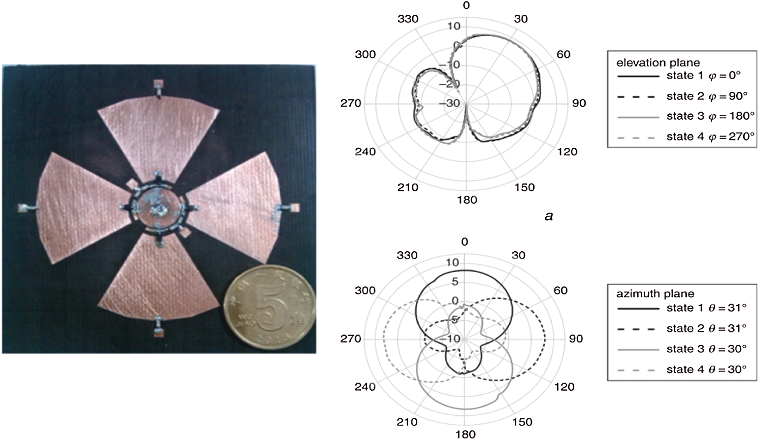
Figure 10: Fabricated antenna and measured radiation patterns at 3.5 GHz in the elevation planes of ϕ = 0°, 90°, 180° and 270° and in the azimuth planes of θ = 30° and 31° [101]
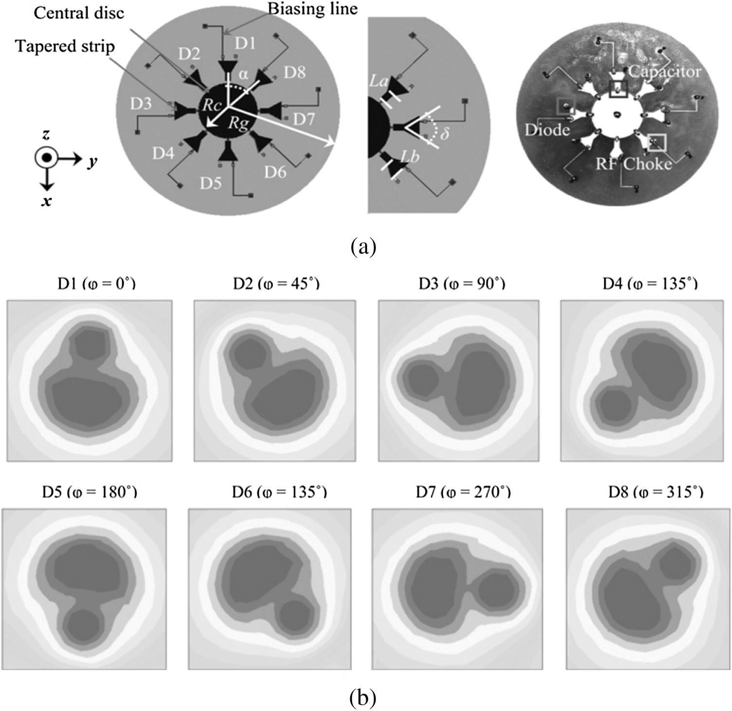
Figure 11: (a) Antenna geometry (b) Orientation of the E-field at different switching conditions at 2.4 GHz [102]
Reconfigurable antenna with the combination of patch, pixel and parasitic elements was reported in [103]. The three-layer antenna designed structure can be seen in Fig. 12. The parasitic strip elements were mutually coupling by the energy strength of a driven patch antenna. It was reported that 6 PIN diodes were located in between pixels in each strip and controlled by bias lines at the bottom surface layer for achieved steering. The result shows a reconfigurable antenna capable of the tilted range between −40° and +40° in nine broadside directions at a frequency of 5 GHz with 8 dBi average gain. Compared to other studies [89–90,97,104], this antenna had the capability to choose the optimum mode operation by the used a control algorithm. It has suitable for employed on multiple radiation patterns to solve coverage complicity in a cellular network.
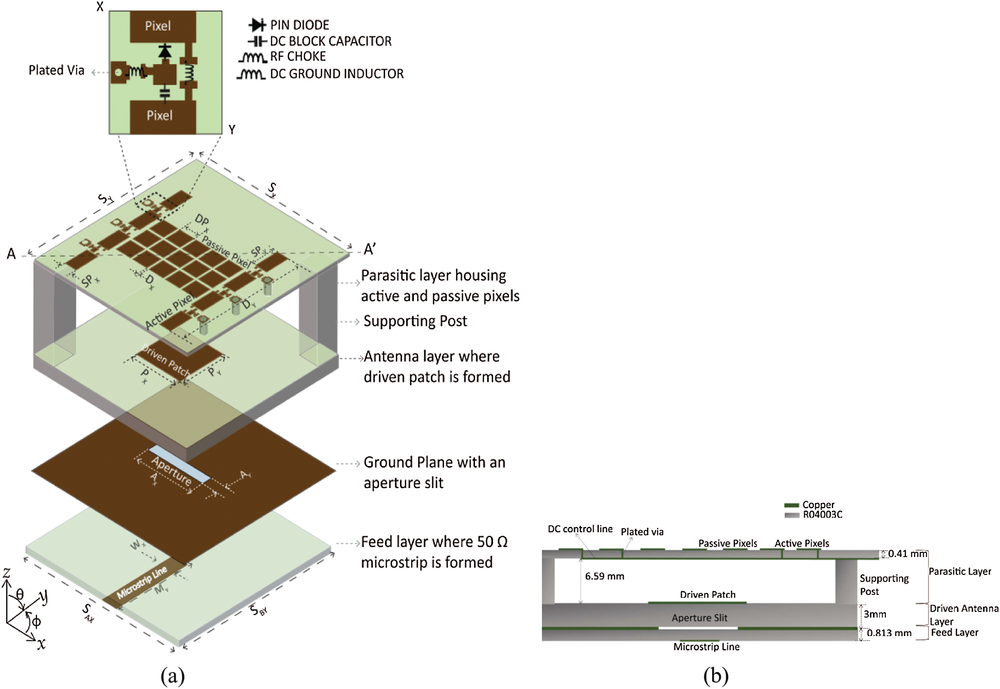
Figure 12: (a) 3-D view of Reconfigurable Antenna (b) Plane cross-section [103]
In another notable work [105], it can be seen in Fig. 13 that the antenna was designed with a combination of a square shape patch driven antenna with two parasitic elements. The strengthening of coupling energy from driven patch to parasitic depends on the change of currents flow controlled by the capacitance of 2 varactor diodes that are loaded in the hexagonal slot. This reconfigurable antenna also achieved the H-plane steers the beam from −40° to +40° with 3.36 dBi of gain at broadside directional without any impedance matching involved within the frequency range of 2.43 to 2.47 GHz.

Figure 13: (a) Front view and (b) Side view of the reconfigurable parasitic antenna [105]
The generally served purpose of pattern reconfigurable antenna is beam steering. However, in some applications, the beam-shaping is needed to reconfigure the HPBW, directivity and gain of the antenna. Such pattern reconfigurable antennas are categorized as beam shaping antennas and are reviewed in this section. In previous work of [90] was designed a driven patch on the top layer while the other two large parasitic patches (LPPs) were located in the middle layer using Rogers 3003 substrate to operate at 3.32 to 3.51 GHz. It can be seen from Fig. 14 that the low-profile antenna fed by aperture coupled using FR4 as substrate, demonstrated high isolation among two ports and wide bandwidth. This antenna achieved reconfigurability by using the 8 PIN diodes to perform four radiation modes by connecting or disconnecting it to LPP1 and LPP2 via the ground plane. While the LPP connected to the ground, the PIN diodes acted as a director at the ON condition caused by decreased an electric length at LPP. Otherwise, the LPP acted as a reflector, because of increased the electric length at the OFF condition. Tab. 3 shows the three-layer planar design antenna achieved a wide beam radiation pattern with half-power beamwidth between −52° to +53° and it covered the other three narrow beam angle between −53° to +47°. That made it suitable for improved the quality and capacity at a small station like microbase station application.

Figure 14: (a–c) Geometry of the pattern reconfigurable Yagi Patch antenna [90]

The [106,107] presented an efficient way-out by separating a reconfigurable parasitic layer from a driven antenna. This method employed the concept of Partial Reflective Surface (PRS) to control the driven patch vicinity. The PRS has obtained dynamical control by altering the surface reflective properties and contributing at high gain [108]. The recent study in [103] employs that concept where no connection switch applied at pixels for a changeable reflection phase to achieve beam shaping. It can be seen from Fig. 15 where the radiation patterns from modes configurable patch antenna were plotted. This study has been using the grid 3 × 5 of un-interconnected square metallic pixel elements from the material Rogers R04003C substrate at the parasitic layer achieved the 8 dBi gain of energy length. It shows that the technique contributed to achieving θ3 dB = 40° and 100° at the narrow beam and broad beam in a broadside direction, respectively. However, it can be clearly analyzed that added of the parasitic layer had led to a decrease to 14% of the efficiency of the antenna compared if without using the parasitic layer. Anyhow, the reduction to RF loss can be improved by employing less additional circuitry at added layer because of no switch applied at pixels.

Figure 15: Radiation patterns for various RA modes and the patch antenna in a typical cell [103]
In [109] had a theoretical study explained of E-plane and H-plane performance referred to Liquid crystal (LC) reconfiguration. The study reported that the 3 dB-beamwidth changing by contributed the differing value of dielectric properties on LC substrate. As shown in Fig. 16, the permittivity ɛr increased when the biasing voltage strength increases resulted on increasing of 3 dB-beamwidth, but it affected to decrease of pattern directivity. This study was reported by obtained in less than 2.8% of the maximum error between theoretical and simulated results.
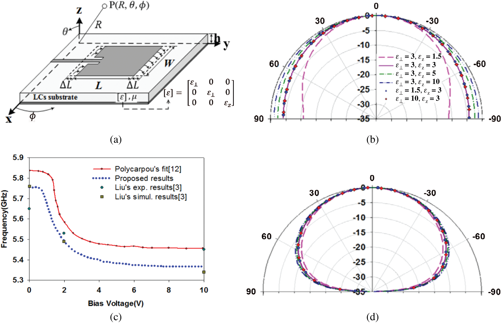
Figure 16: Rectangular microstrip patch antenna [109] (a) Geometry of rectangular patch antenna of LC substrates (b) Antenna resonant frequency vs. voltage (c) Theoretical normalized radiation patterns as function of anisotropic permittivity of liquid crystal E-plane (d) Theoretical normalized radiation patterns as function of anisotropic permittivity of liquid crystal H-plane
It can be concluded over the discussion on the variety designs, and their performance shows that the patterns improvement in reconfigurable antennas is possible for advance mid-band 5G communication systems. Most studies showed the challenges by implementing the PIN diodes as the complicated cause by biasing circuit that additional passive elements like capacitors and inductors that affected in return loss performance and efficiency either the contribute to design complexity. The changing of dimension and antenna structure will affect the antenna performances and operating frequency. Beam steering and beam shaping had better solution for less power consumption, dynamically optimize for better coverage and capacity on network. The challenges on high steering resolution at broadsides and the required of numbers on beamwidth configuration had intently needed to relieve the congestion and provide fast quality signal toward null interference, shadowing, and energy waste. The size of bandwidth is required to take account for the accommodation of 5G speed and latency aims.
Future study should ideally be considered, such as a combination of elements, the number of switches being using, exploring the pixels adaptation, deploying a truncated ground, multi-layer, aperture coupled and other expected techniques. Additionally, the efficient cost and less complex structure design require some effort for extraordinary experimental to go through. The increasing design sensitivity that influenced the efficiency, interference, stability, spurious emission and other transmission loss are highlighted for mid-band 5G communication systems to broaden its potential for future research. This subject can be tackled along with considering the advanced computer control technology in antenna design and fabrication. The knowledge delivered in this paper on pattern features of reconfigurable antenna can be regarded as a starting platform for progress studies on its improvement.
Funding Statement: This work was supported by the Deanship of Scientific Research at Prince Sattam bin Abdulaziz University, Saudi Arabia.
Conflicts of Interest: The authors declare that they have no conflicts of interest to report regarding the present study.
1. N. Kumar, P. Kumar and M. Sharma, “Reconfigurable antenna and performance optimization approach,” Wireless Personal Communications, vol. 112, pp. 2187–2212, 2020. [Google Scholar]
2. A. Kumbhar, “Overview of ISM bands and software-defined radio,” Wireless Personal Communications, vol. 97, pp. 3743–3756, 2017. [Google Scholar]
3. D. A. Sehrai, F. Muhammad, S. H. Kiani, Z. H. Abbas, M. Tufail et al., “Gain-enhanced metamaterial based antenna for 5G communication standards,” Computers, Materials and Continua, vol. 64, no. 3, pp. 1587–1599, 2020. [Google Scholar]
4. P. Reba, G. U. Maheswari and M. S. Babu, “Multiple antenna selection for underlay cognitive radio systems with interference constraint,” Wireless Personal Communications, vol. 98, no. 1, pp. 1505–1520, 2018. [Google Scholar]
5. V. A. Raju, B. T. P. Madhav, P. R. Rao, A. Mukherjee and V. Soundarya, “Analysis of high gain 4X4 square patch antenna array for wireless applications,” Indian Journal of Science and Technology, vol. 9, no. 48, pp. 1–7, 2016. [Google Scholar]
6. G. Makar, D. Kim, N. Tran and T. Karacolak, “Compact antennas with reduced self interference for simultaneous transmit and receive,” Progress in Electromagnetics Research C, vol. 78, pp. 19–31, 2017. [Google Scholar]
7. I. Uchendu and J. Kelly, “Survey of beam steering techniques available for millimeter wave applications,” Progress in Electromagnetics Research, vol. 68, no. 1, pp. 35–54, 2016. [Google Scholar]
8. A. Ghosh, S. Member, T. A. Thomas, M. C. Cudak, R. Ratasuk et al., “Millimeter-wave enhanced local area systems: A high-data-rate approach for future wireless networks,” IEEE Journal on Selected Areas in Communications, vol. 32, no. 6, pp. 1152–1163, 2014. [Google Scholar]
9. M. A. Habibi, M. Nasimi, B. Han and H. D. Schotten, “A comprehensive survey of RAN architectures toward 5G mobile communication system,” IEEE Access, vol. 7, pp. 70371–70421, 2019. [Google Scholar]
10. S. N. M. Zainarry, S. J. Chen and C. Fumeaux, “A pattern-reconfigurable single-element microstrip antenna,” in 2018 IEEE Radio and Antenna Days of the Indian Ocean, RADIO 2018, Wolmar, Mauritius, pp. 1–2, 2018. [Google Scholar]
11. Z. Park and J. Lin, “A beam-steering broadband microstrip antenna for noncontact vital sign detection,” IEEE Antennas and Wireless Propagation Letters, vol. 10, pp. 235–238, 2011. [Google Scholar]
12. K. V. Chandra, M. Satyanarayana and K. T. Battula, “A novel miniature hexagonal shape switched pattern and frequency reconfigurable antenna,” International Journal of Communication Systems, vol. 33, no. 5, pp. 2–9, 2020. [Google Scholar]
13. D. Rodrigo, L. Jofre and B. A. Cetiner, “Circular beam-steering reconfigurable antenna with liquid metal parasitics,” IEEE Transactions on Antennas and Propagation, vol. 60, no. 4, pp. 1796–1802, 2012. [Google Scholar]
14. C. W. Baek, S. Song, C. Cheon, Y. K. Kim and Y. Kwon, “2-D mechanical beam steering antenna fabricated using MEMS technology,” in IEEE MTT-S Int. Microwave Symp. Digest, Phoenix, AZ, USA, vol. 3, pp. 211–214, 2001. [Google Scholar]
15. M. H. Dahri, M. H. Jamaluddin, M. I. Abbasi and M. R. Kamarudin, “A review of wideband reflectarray antennas for 5G communication systems,” IEEE Access, vol. 5, pp. 17803–17815, 2017. [Google Scholar]
16. F. A. Asadallah, H. A. Khalek, B. A. A. Modad, J. A. Hosn, J. Costantine et al., “A miniaturized reconfigurable UHF antenna,” in 2018 IEEE Int. Symp. on Antennas and Propagation & USNC/URSI National Radio Science Meeting, Boston, Massachusetts, USA, pp. 295–296, 2018. [Google Scholar]
17. N. Nguyen-Trong, L. Hall and C. Fumeaux, “A frequency- and pattern-reconfigurable center-shorted microstrip antenna,” IEEE Antennas and Wireless Propagation Letters, vol. 15, pp. 1955–1958, 2016. [Google Scholar]
18. X. Guo, Y. Hang, Z. Xie, C. Wu, G. Le et al., “Flexible and wearable 2.45 GHz CPW-FED antenna using inkjet-printing of silver nanoparticles of pet,” Microwave and Optical Technology Letters, vol. 59, no. 1, pp. 204–208, 2017. [Google Scholar]
19. H. Tian, K. Dhwaj, L. J. Jiang and T. Itoh, “Beam scanning realized by coupled modes in a single-patch antenna,” IEEE Antennas and Wireless Propagation Letters, vol. 17, no. 6, pp. 1077–1080, 2018. [Google Scholar]
20. B. Patir, “A review on various techniques of microstrip patch antenna design for wireless application,” International Journal of Computer Applications, vol. 1, pp. 15–17, 2015. [Google Scholar]
21. Y. M. Cai, K. Li, Y. Yin, S. Gao, W. Hu et al., “A low-profile frequency reconfigurable grid-slotted patch antenna,” IEEE Access, vol. 6, pp. 36305–36312, 2018. [Google Scholar]
22. H. C. Mohanta, A. Z. Kouzani and S. K. Mandal, “Reconfigurable antennas and their applications,” Universal Journal of Electrical and Electronic Engineering, vol. 6, no. 4, pp. 239–258, 2019. [Google Scholar]
23. N. O. Parchin, H. J. Basherlou, Y. I. A. Al-Yasir, A. M. Abdulkhaleq and R. A. Abd-Alhameed, “Reconfigurable antennas: Switching techniques—A survey,” Electronics (Switzerland), vol. 9, no. 336, pp. 1–14, 2020. [Google Scholar]
24. Z. L. Lu, X. X. Yang and G. N. Tan, “A multidirectional pattern-reconfigurable patch antenna with CSRR on the ground,” IEEE Antennas and Wireless Propagation Letters, vol. 16, pp. 416–419, 2017. [Google Scholar]
25. B. Ban, Z. Cheng and S. L. Chen, “Center-fed shorting-via-loaded circular patch antenna with reconfigurable polarization and switchable beam,” in 2018 12th Int. Symp. on Antennas, Propagation and EM Theory, ISAPE 2018-Proc., Hangzhou, China, pp. 1–3, 2019. [Google Scholar]
26. M. Jusoh, T. Sabapathy, M. F. Jamlos and M. R. Kamarudin, “Reconfigurable four-parasitic-elements patch antenna for high-gain beam switching application,” IEEE Antennas and Wireless Propagation Letters, vol. 13, pp. 79–82, 2014. [Google Scholar]
27. F. Gao, G. Shen, J. Lu and W. Wang, “A low profile pattern reconfigurable antenna with enhanced bandwidth and gain,” in 2017 IEEE Int. Symp. on Antennas and Propagation & USNC/URSI National Radio Science Meeting, San Diego, California, USA, pp. 1647–1648, 2017. [Google Scholar]
28. P. Lotfi, S. Soltani and R. D. Murch, “Broadside beam-steerable planar parasitic pixel patch antenna,” IEEE Transactions on Antennas and Propagation, vol. 64, no. 10, pp. 4519–4524, 2016. [Google Scholar]
29. N. O. Parchin, H. J. Basherlou, Y. I. A. Al-Yasir, R. A. Abd-Alhameed, A. M. Abdulkhaleq et al., “Recent developments of reconfigurable antennas for current and future wireless communication systems,” Electronics (Switzerland), vol. 8, no. 128, pp. 1–17, 2019. [Google Scholar]
30. T. Sabapathy, R. B. Ahmad, M. Jusoh, M. R. Kamarudin and A. Alomainy, “A pattern-reconfigurable parasitic patch antenna using BAR and HPND PIN diode,” in 8th European Conf. on Antennas and Propagation, EuCAP 2014, The Hague, Netherlands, pp. 3444–3445, 2014. [Google Scholar]
31. T. Sabapathy, M. Jusoh, P. J. Soh, R. B. Ahmad and M. R. Kamarudin, “Radiation pattern reconfigurable antenna: The design challenges at GHz frequencies,” in 2016 IEEE Asia-Pacific Conf. on Applied Electromagnetics, APACE 2016, Langkawi, Malaysia, pp. 301–304, 2016. [Google Scholar]
32. S. N. M. Zainarry, N. Nguyen-Trong and C. Fumeaux, “A frequency- and pattern-reconfigurable two-element array antenna,” IEEE Antennas and Wireless Propagation Letters, vol. 17, no. 4, pp. 617–620, 2018. [Google Scholar]
33. W. M. Abdulkawi, W. A. Malik, A. F. A. Sheta and M. A. Alkanhal, “A compact dual circular patch pattern reconfigurable antenna,” Microwave and Optical Technology Letters, vol. 60, no. 11, pp. 2762–2768, 2018. [Google Scholar]
34. M. Saravanan and M. J. S. Rangachar, “Design of hexagonal shape reconfigurable antenna for wireless communications,” Modelling, Measurement and Control A, vol. 91, no. 2, pp. 37–40, 2018. [Google Scholar]
35. I. A. Shah, S. Hayat, A. Basir, M. Zada, S. A. A. Shah et al., “Design and analysis of a hexa-band frequency reconfigurable antenna for wireless communication,” AEU-International Journal of Electronics and Communications, vol. 98, pp. 80–88, 2019. [Google Scholar]
36. S. J. Mazlouman, A. Mahanfar, C. Menon and R. G. Vaughan, “A review of mechanically reconfigurable antennas using smart material actuators,” in Proc. of the 5th European Conf. on Antennas and Propagation, EUCAP 2011, Rome, Italy, pp. 1076–1079, 2011. [Google Scholar]
37. P. Sanchez-Olivares and J. L. Masa-Campos, “Mechanically reconfigurable conformal array antenna fed by radial waveguide divider with tuning screws,” IEEE Transactions on Antennas and Propagation, vol. 65, no. 9, pp. 4886–4890, 2017. [Google Scholar]
38. C. J. Panagamuwa, A. Chauraya and J. C. Vardaxoglou, “Frequency and beam reconfigurable antenna using photoconducting switches,” IEEE Transactions on Antennas and Propagation, vol. 54, no. 2, pp. 449–454, 2006. [Google Scholar]
39. R. Morris, C. Jones and M. Nagaraj, “Liquid crystal devices for beam steering applications,” Micromachines, vol. 12, no. 247, pp. 1–27, 2021. [Google Scholar]
40. M. Wang, M. R. Khan, M. D. Dickey and J. J. Adams, “A compound frequency- and polarization- reconfigurable crossed dipole using multidirectional spreading of liquid metal,” IEEE Antennas and Wireless Propagation Letters, vol. 16, pp. 79–82, 2017. [Google Scholar]
41. L. Song, W. Gao, C. O. Chui and Y. Rahmat-Samii, “Wideband frequency reconfigurable patch antenna with switchable slots based on liquid metal and 3-D printed microfluidics,” IEEE Transactions on Antennas and Propagation, vol. 67, no. 5, pp. 2886–2895, 2019. [Google Scholar]
42. L. G. Silva, A. A. C. Alves and A. C. Sodré, “Optically controlled reconfigurable filtenna,” International Journal of Antennas and Propagation, vol. 2016, pp. 1–9, 2016. [Google Scholar]
43. M. Donelli, “A simple and efficient adaptive ISM-band antenna based on a reconfigurable optically driven parasitic structure,” Electronics (Switzerland), vol. 7, no. 21, pp. 1–18, 2018. [Google Scholar]
44. I. F. da Costa, H. R. D. Filgueiras, J. R. Kelly, A. C. S. Jr. and P. Xiao, “Mechanical beam steering circular patch antenna,” in 12th European Conf. on Antennas and Propagation, EuCAP 2018, London, UK, pp. 1–4, 2018. [Google Scholar]
45. F. Alsharif, S. Safi, T. AbouFoul, M. A. Nasr and S. A. Nasser, “Mechanical reconfigurable microstrip antenna,” International Journal of Microwave and Optical Technology, vol. 11, no. 3, pp. 153–160, 2016. [Google Scholar]
46. S. M. A. M. H. Abadi, J. H. Booske and N. Behdad, “Exploiting mechanical flexure as a means of tuning the responses of large-scale periodic structures,” IEEE Transactions on Antennas and Propagation, vol. 64, no. 3, pp. 933–943, 2016. [Google Scholar]
47. A. Jouade, M. Himdi, A. Chauloux and F. Colombel, “Mechanically pattern-reconfigurable bended horn antenna for high-power applications,” IEEE Antennas and Wireless Propagation Letters, vol. 16, pp. 457–460, 2017. [Google Scholar]
48. J. H. Dang, R. C. Gough, A. M. Morishita, A. T. Ohta and W. A. Shiroma, “Liquid-metal-based reconfigurable components for RF front ends,” IEEE Potentials, vol. 34, no. 4, pp. 24–30, 2015. [Google Scholar]
49. M. D. Dickey, “Emerging applications of liquid metals featuring surface oxides,” ACS Applied Materials and Interfaces, vol. 6, no. 21, pp. 18369–18379, 2014. [Google Scholar]
50. J. B. Yan, S. Yong and J. T. Bernhard, “Intermodulation and harmonic distortion in frequency reconfigurable slot antenna pairs,” IEEE Transactions on Antennas and Propagation, vol. 62, no. 3, pp. 1138–1146, 2014. [Google Scholar]
51. C. Wang, J. C. Yeo, H. Chu, C. T. Lim and Y. X. Guo, “Design of a reconfigurable patch antenna using the movement of liquid metal,” IEEE Antennas and Wireless Propagation Letters, vol. 17, no. 6, pp. 974–977, 2018. [Google Scholar]
52. Y. Zhang, S. Lin, Z. Yang, B. Li, J. Cui et al., “A pattern- and frequency-reconfigurable antenna using liquid metal,” Microwave and Optical Technology Letters, vol. 63, no. 5, pp. 1499–1506, 2021. [Google Scholar]
53. D. Abijuru, M. R. Hamid and A. N. Obadiah, “Improved vivaldi antenna with radiation pattern control features,” TELKOMNIKA (Telecommunication Computing Electronics and Control), vol. 16, no. 3, pp. 1143–1149, 2018. [Google Scholar]
54. N. W. Liu, L. Zhu, W. W. Choi and G. Fu, “A low-profile wideband aperture-fed microstrip antenna with improved radiation patterns,” IEEE Transactions on Antennas and Propagation, vol. 67, no. 1, pp. 562–567, 2019. [Google Scholar]
55. K. E. Kedze, H. Wang and I. Park, “Compact broadband omnidirectional radiation pattern printed dipole antenna incorporated with split-ring resonators,” IEEE Access, vol. 6, pp. 49537–49545, 2018. [Google Scholar]
56. M. Kashanianfard and K. Sarabandi, “Directional full-duplex RF booster for 2450 MHz ISM band,” IEEE Transactions on Antennas and Propagation, vol. 65, no. 1, pp. 134–141, 2017. [Google Scholar]
57. N. A. Jan, S. H. Kiani, D. A. Sehrai, M. R. Anjum, A. Iqbal et al., “Design of a compact monopole antenna for UWB applications,” computers,” Materials and Continua, vol. 66, no. 1, pp. 35–44, 2021. [Google Scholar]
58. G. A. R. Arroyave, A. Barlabé, L. Pradell, J. L. A. Quijano, B. A. Cetiner et al., “Design of minimum nonlinear distortion reconfigurable antennas for next-generation communication systems,” Sensors, vol. 21, no. 2557, pp. 1–25, 2021. [Google Scholar]
59. S. K. Sharma and L. Shafai, “Beam focusing properties of circular monopole array antenna on a finite ground plane,” IEEE Transactions on Antennas and Propagation, vol. 53, no. 10, pp. 3406–3409, 2005. [Google Scholar]
60. K. L. Lau and K. M. Luk, “A wide-band monopolar wire-patch antenna for indoor base station applications,” IEEE Antennas and Wireless Propagation Letters, vol. 4, pp. 155–157, 2005. [Google Scholar]
61. Y. Tawk, J. Costantine, F. Makhlouf, M. Nassif, L. Geagea et al., “Wirelessly automated reconfigurable antenna with directional selectivity,” IEEE Access, vol. 5, pp. 802–811, 2017. [Google Scholar]
62. S. A. A. Shah, M. F. Khan, S. Ullah, A. Basir, U. Ali et al., “Design and measurement of planar monopole antennas for multi-band wireless applications,” IETE Journal of Research, vol. 63, no. 2, pp. 194–204, 2017. [Google Scholar]
63. Y. Juan, W. Che, W. Yang and Z. N. Chen, “Compact pattern-reconfigurable monopole antenna using parasitic strips,” IEEE Antennas and Wireless Propagation Letters, vol. 16, pp. 557–560, 2017. [Google Scholar]
64. G. Jin, M. Li, D. Liu and G. Zeng, “A simple four-beam reconfigurable antenna based on monopole,” IEEE Access, vol. 6, pp. 30309–30316, 2018. [Google Scholar]
65. K. Yang, A. Loutridis, X. Bao, G. Ruvio and M. J. Ammann, “Printed inverted-F antenna with reconfigurable pattern and polarization,” in 2016 10th European Conf. on Antennas and Propagation, EuCAP 2016, Davos, Switzerland, pp. 1–5, 2016. [Google Scholar]
66. I. Ben Trad, J. M. Floc'H, H. Rmili, M. Drissi and F. Choubani, “A planar reconfigurable radiation pattern dipole antenna with reflectors and directors for wireless communication applications,” International Journal of Antennas and Propagation, vol. 2014, pp. 1–10, 2014. [Google Scholar]
67. J. Huang and A. C. Densmore, “Microstrip yagi array antenna for mobile satellite vehicle application,” IEEE Transactions on Antennas and Propagation, vol. 39, no. 7, pp. 1024–1030, 1991. [Google Scholar]
68. A. Sondas, “A wideband microstrip dipole antenna design for WLAN/WiMAX applications,” Advanced Electromagnetics, vol. 8, no. 2, pp. 59–62, 2019. [Google Scholar]
69. M. C. Tang, B. Zhou, Y. Duan, X. Chen and R. W. Ziolkowski, “Pattern-reconfigurable, flexible, wideband, directive, electrically small near-field resonant parasitic antenna,” IEEE Transactions on Antennas and Propagation, vol. 66, no. 5, pp. 2271–2280, 2018. [Google Scholar]
70. J. Zeng and K. Luk, “A simple wideband magnetoelectric dipole antenna with a defected ground structure,” IEEE Antennas and Wireless Propagation Letters, vol. 17, no. 8, pp. 1497–1500, 2018. [Google Scholar]
71. K.-M. Luk and H. Wong, “A new wideband unidirectional antenna element,” International Journal of Microwave and Optical Technology, vol. 1, no. 1, pp. 35–44, 2006. [Google Scholar]
72. H. Wong, M. Ka-Ming and L. Kwai-Man, “Wideband shorted bowtie patch antenna with electric dipole,” IRE Transactions on Antennas and Propagation, vol. 56, no. 7, pp. 2098–2101, 2008. [Google Scholar]
73. Z. Wang, J. Wu, Y. Yin and X. Liu, “A broadband dual-element folded dipole antenna with a reflector,” IEEE Antennas and Wireless Propagation Letters, vol. 13, pp. 750–753, 2014. [Google Scholar]
74. H. A. Majid, M. K. A. Rahim, M. R. Hamid and M. F. Ismail, “Frequency and pattern reconfigurable slot antenna,” IEEE Transactions on Antennas and Propagation, vol. 62, no. 10, pp. 5339–5343, 2014. [Google Scholar]
75. Y. P. Selvam, M. G. N. Alsath, M. Kanagasabai, L. Elumalai, S. K. Palaniswamy et al., “A patch-slot antenna array with compound reconfiguration,” IEEE Antennas and Wireless Propagation Letters, vol. 17, no. 3, pp. 525–528, 2018. [Google Scholar]
76. B. Ratni, E. Bochkova, G. P. Piau, A. de Lustrac, A. Lupu et al., “Design and engineering of metasurfaces for high-directivity antenna and sensing applications,” EPJ Applied Metamaterials, vol. 3, no. 4, pp. 1–10, 2016. [Google Scholar]
77. M. Casaletti, G. Valerio, O. Quevedo-Teruel and P. Burghignoli, “An overview of metasurfaces for thin antenna applications,” Comptes Rendus Physique, vol. 21, no. 7–8, pp. 659–676, 2020. [Google Scholar]
78. S. Chaimool, T. Hongnara, C. Rakluea, P. Akkaraekthalin and Y. Zhao, “Design of a PIN diode-based reconfigurable metasurface antenna for beam switching applications,” International Journal of Antennas and Propagation, vol. 2019, pp. 1–7, 2019. [Google Scholar]
79. K. L. Chung, H. Tian, C. Song and C. Zhang, “A study into the PIN diode-based active metasurface for beam steering applications,” in 2017 Int. Symp. on Antennas and Propagation, ISAP 2017, Phuket, Thailand, pp. 1–2, 2017. [Google Scholar]
80. H. Zhu, Y. Qiu, J. Bai and G. Wei, “Compact design of non-uniform meta-surface for patch antenna main beam steering,” Applied Computational Electromagnetics Society Journal, vol. 34, no. 9, pp. 1300–1304, 2019. [Google Scholar]
81. A. Kumar, N. Gupta and P. C., “Gain and bandwidth enhancement techniques in microstrip patch antennas—A review,” International Journal of Computer Applications, vol. 148, no. 7, pp. 9–14, 2016. [Google Scholar]
82. G. Yang, J. Li, D. Wei, S. G. Zhou and R. Xu, “Pattern reconfigurable microstrip antenna with multidirectional beam for wireless communication,” IEEE Transactions on Antennas and Propagation, vol. 67, no. 3, pp. 1910–1915, 2019. [Google Scholar]
83. L. Han, C. Wang, W. Zhang, R. Ma and Q. Zeng, “Design of frequency and pattern-reconfigurable wideband slot antenna,” International Journal of Antennas and Propagation, vol. 2018, pp. 1–7, 2018. [Google Scholar]
84. C. A. Balanis, Antenna Theory: Analysis and Design, 4th ed., Hoboken, New Jersey, USA: John Wiley & Sons, Inc., 2016. [Google Scholar]
85. S. Kim and J. Choi, “Beam steering antenna with reconfigurable parasitic elements for FPV drone applications,” Microwave and Optical Technology Letters, vol. 60, no. 9, pp. 2173–2177, 2018. [Google Scholar]
86. V. V. Khairnar, C. K. Ramesha and L. J. Gudino, “A survey on beamwidth reconfigurable antennas,” in Lecture Notes in Electrical Engineering. Germany: Springer Verlag, vol. 659, pp. 487–494, 2020. [Google Scholar]
87. W. Lin, H. Wong and R. W. Ziolkowski, “Circularly polarized antenna with reconfigurable broadside and conical beams facilitated by a mode switchable feed network,” IEEE Transactions on Antennas and Propagation, vol. 66, no. 2, pp. 996–1001, 2018. [Google Scholar]
88. D. Rodrigo, B. A. Cetiner and L. Jofre, “Frequency, radiation pattern and polarization reconfigurable antenna using a parasitic pixel layer,” IEEE Transactions on Antennas and Propagation, vol. 62, no. 6, pp. 3422–3427, 2014. [Google Scholar]
89. Z. Li, E. Ahmed, A. M. Eltawil and B. A. Cetiner, “A beam-steering reconfigurable antenna for WLAN applications,” IEEE Transactions on Antennas and Propagation, vol. 63, no. 1, pp. 24–32, 2015. [Google Scholar]
90. W. Q. Deng, X. S. Yang, C. S. Shen, J. Zhao and B. Z. Wang, “A dual-polarized pattern reconfigurable yagi patch antenna for microbase stations,” IEEE Transactions on Antennas and Propagation, vol. 65, no. 10, pp. 5095–5102, 2017. [Google Scholar]
91. H. Moghadas, M. Daneshmand and P. Mousavi, “MEMS-Tunable half phase gradient partially reflective surface for beam-shaping,” IEEE Transactions on Antennas and Propagation, vol. 63, no. 1, pp. 369–373, 2015. [Google Scholar]
92. A. Ourir, S. N. Burokur and A. de Lustrac, “Electronic beam steering of an active metamaterial-based directive subwavelength cavity,” IET Seminar Digest, vol. 2007, pp. 1–4, 2007. [Google Scholar]
93. T. Sabapathy, M. Jusoh, R. B. Ahmad and M. R. Kamarudin, “A low profile dual-mode reconfigurable antenna design,” in Lecture Notes in Electrical Engineering. Germany: Springer Verlag, vol. 344, pp. 239–246, 2015. [Google Scholar]
94. R. A. Pandhare, P. L. Zade and M. P. Abegaonkar, “Beam-steering in microstrip patch antenna array using DGS based phase shifters at 5.2 GHz,” in Proc.-IEEE Int. Conf. on Information Processing, ICIP 2015, Pune, India, pp. 239–243, 2016. [Google Scholar]
95. H. Rajagopalan and Y. Rahmat-Samii, “Dielectric and conductor loss quantification for microstrip reflectarray: Simulations and measurements,” IEEE Transactions on Antennas and Propagation, vol. 56, no. 4, pp. 1192–1196, 2008. [Google Scholar]
96. T. Sabapathy, M. F. Jamlos, R. B. Ahmad, M. Jusoh, M. I. Jais et al., “Electronically reconfigurable beam steering antenna using embedded RF PIN based parasitic arrays (ERPPA),” Progress in Electromagnetics Research, vol. 140, pp. 241–261, 2013. [Google Scholar]
97. M. Jusoh, T. Aboufoul, T. Sabapathy, A. Alomainy and M. R. Kamarudin, “Pattern-reconfigurable microstrip patch antenna with multidirectional beam for WiMAX application,” IEEE Antennas and Wireless Propagation Letters, vol. 13, pp. 860–863, 2014. [Google Scholar]
98. T. Sabapathy, M. Jusoh, R. B. Ahmad, M. R. Kamarudin and P. J. Soh, “A ground-plane-truncated, broadly steerable yagi-uda patch array antenna,” IEEE Antennas and Wireless Propagation Letters, vol. 15, pp. 1069–1072, 2016. [Google Scholar]
99. Z. Li, I. Bahceci and B. A. Cetiner, “Broadband beam-steering reconfiguring antenna,” Microwave and Optical Technology Letters, vol. 59, no. 1, pp. 63–65, 2017. [Google Scholar]
100. M. Chinmayarangaraj, R. V. S. Satyanarayana and H. Mopidevi, “Design and parametric analysis of pattern reconfigurable patch fed ring slot antenna,” International Journal of Advanced Research in Electronics and Communication Engineering, vol. 6, no. 1, pp. 84–87, 2016. [Google Scholar]
101. S.-J. Shi and W.-P. Ding, “Radiation pattern reconfigurable microstrip antenna for WiMAX application,” Electronics Letters, vol. 51, no. 9, pp. 662–664, 2015. [Google Scholar]
102. A. Abbosh and M. S. Alam, “Planar pattern reconfigurable antenna with eight switchable beams for wiMax and WLAN applications,” IET Microwaves, Antennas & Propagation, vol. 10, no. 10, pp. 1030–1035, 2016. [Google Scholar]
103. M. A. Towfiq, I. Bahceci, S. Blanch, J. Romeu, L. Jofre et al., “A reconfigurable antenna with beam steering and beamwidth variability for wireless communications,” IEEE Transactions on Antennas and Propagation, vol. 66, no. 10, pp. 5052–5063, 2018. [Google Scholar]
104. T. Debogović and J. Perruisseau-Carrier, “Array-fed partially reflective surface antenna with independent scanning and beamwidth dynamic control,” IEEE Transactions on Antennas and Propagation, vol. 62, no. 1, pp. 446–449, 2014. [Google Scholar]
105. V. V. Khairnar, B. V. Kadam, C. K. Ramesha and L. J. Gudino, “A reconfigurable parasitic antenna with continuous beam scanning capability in H-plane,” AEU-International Journal of Electronics and Communications, vol. 88, pp. 78–86, 2018. [Google Scholar]
106. Z. Li, H. Mopidevi, O. Kaynar and B. A. Cetiner, “Beam-steering antenna based on parasitic layer,” Electronics Letters, vol. 48, no. 2, pp. 59–60, 2012. [Google Scholar]
107. X. Yuan, Z. Li, D. Rodrigo, H. S. Mopidevi, O. Kaynar et al., “A parasitic layer-based reconfigurable antenna design by multi-objective optimization,” IEEE Transactions on Antennas and Propagation, vol. 60, no. 6, pp. 2690–2701, 2012. [Google Scholar]
108. A. R. Weily, T. S. Bird and Y. J. Guo, “A reconfigurable high-gain partially reflecting surface antenna,” IEEE Transactions on Antennas and Propagation, vol. 56, no. 11, pp. 3382–3390, 2008. [Google Scholar]
109. T. W. Kim, J. S. Park and S. O. Park, “A theoretical model for resonant frequency and radiation pattern on rectangular microstrip patch antenna on liquid crystal substrate,” IEEE Transactions on Antennas and Propagation, vol. 66, no. 9, pp. 4533–4540, 2018. [Google Scholar]
 | This work is licensed under a Creative Commons Attribution 4.0 International License, which permits unrestricted use, distribution, and reproduction in any medium, provided the original work is properly cited. |