DOI:10.32604/cmc.2022.020688
| Computers, Materials & Continua DOI:10.32604/cmc.2022.020688 | |
| Article |
A Compact Tri-Band Antenna Based on Inverted-L Stubs for Smart Devices
1Department of Information and Communication Engineering, Chungbuk National University, Cheongju, 28644, Korea
2Department of Information and Communication Engineering, Kongju National University, Kongju, 32588, Korea
*Corresponding Author: Nam Kim. Email: namkim@chungbuk.ac.kr
Received: 02 June 2021; Accepted: 03 July 2021
Abstract: We designed and constructed a novel, compact tri-band monopole antenna for intelligent devices. Multiband behavior was achieved by placing inverted-L shaped stubs of various lengths in a triangular monopole antenna fed by a coplanar waveguide. The resonance frequency of each band can be controlled by varying the length of the corresponding stub. Three bands, at 2.4 (2.37–2.51), 3.5 (3.34–3.71), and 5.5 (4.6–6.4) GHz, were easily obtained using three stubs of different lengths. For miniaturization, a portion of the longest stub (at 2.4 GHz) was printed on the opposite side of the substrate, and connected to the main stub via a shorting pin. To validate the concept, the antenna was fabricated on a low-cost 1.6-mm-thick FR-4 substrate with dimensions of 20 × 15 × 1.6 mm3. The antenna exhibited a moderate average gain of 2.9 dBi with an omnidirectional radiations over the bandwidths required for RFID, Bluetooth, ISM, WiMAX, and WLAN-band applications. These features make the antenna suitable for compact smart devices.
Keywords: Multiband antenna; compact antenna; tri-band antenna; CPW antenna; stub-loaded antenna
The need for multiband, planar, low-profile compact antennas has increased given the incorporation of multiple communications systems within a single electronic device. The systems operate at various frequencies ranging from 2 to 7 GHz. Popular frequency bands include the Industrial Scientific and Medical (ISM-2.4 GHz), Bluetooth (2.4 GHz), and long term evolution (LTE-2.5) bands, the 5G sub-6 GHz band (3.5 GHz), and the radio frequency identification (RFID-2.54/5.8 GHz) and wireless local area network (WLAN-2.4/5.2/5.8 GHz) bands. No single antenna can operate in all of these frequency bands; multiple antennas are required. However, the devices must be compact and inexpensive. Therefore, multiband antennas are essential [1].
Printed antennas are cheap, easy to design, have multiband functionality, and are readily integrated with other circuits. Many printed multiband antennas have been developed [2–30]. In [2–7], slots of various shapes were created in a radiator and excited various operating bands. The resonance frequency was controlled by varying the electrical length of the slots. Some studies used asymmetric coplanar strip (ACS)-fed meander lines to ensure multiband operation, while avoiding the need for complex antenna geometries [8,9]. Defected ground structures (DGS) [10,11], stacked layers [12,13], parasitic elements [14,15], and metamaterials have also been employed to create multiband antennas [16–20].
Many tri-band antennas operating in major frequency bands have been used to satisfy bandwidth requirements, and ensure stable gain, high radiation efficiency, and omnidirectional radiation reception [21–30]. A compact tri-band antenna with multiple metallic strips in a dual F-shaped monopole was presented in [21]. This antenna operates in the 1.9, 3.5, and 5.5 GHz bands and has good radiation characteristics. Another tri-band antenna, resonating at 2.4, 3.5, and 5.5 GHz and exhibiting omnidirectional radiation patterns, was proposed in [22]: a truncated rectangular patch, π-shaped slot, and inverted-L slot were used to achieve the required resonance. The antenna has a high radiation efficiency (flat gain of 3.39 dBi).
A uniplanar, ACS-fed tri-band antenna with extended rectangular strips was designed for portable system applications [23]. The antenna has a modified mouse and rectangular radiating strips; three different bands can operate simultaneously. Another ACS-fed F-shaped monopole with a rectangular split-ring resonator for tri-band operation was proposed in [24]. Although simple, all of the antennas described above have unique merits. However, their physical size [25–30] must be reduced for use in modern, multi-functional compact devices.
Simple, miniaturized, highly efficient and inexpensive multiband antennas are required for handheld devices. Here, we present a compact coplanar waveguide-fed tri-band antenna covering several frequency bands, including those of ISM, RFID, Bluetooth, WiMAX, WLAN, and other leading standards (e.g., 5G sub-6 GHz). The antenna has good impedance matching, omnidirectional gain, and moderate bandwidth.
In this section, we discuss the geometry of the tri-band antenna, parameter optimization, and design steps. Initially, the antenna geometry is presented with the design variables, and later design procedure is explained in detail.
2.1 Geometry of the Tri-Band Antenna
The antenna geometry is shown in Fig. 1. Three inverted-L shaped stubs varying in length, but with the same width (w), are connected to a triangular monopole antenna fed by a 50-ohm coplanar waveguide strip line. To minimize size, a portion of the longest stub is printed on the back of the substrate and connected to the other portion via a metallic pin. A low-cost FR-4 substrate with a dielectric constant (εr) of 4.4 and loss tangent (tanδ) of 0.02 was used to print the antenna. The overall footprint of the antenna is given by A × W × h. The optimized parameters of the antenna are as follows: A = 15; L = 20; h = 1.6; wL = 2; s = 1; w = 1; w1 = 13; w2 = 9.8; w3 = 6; w4 = 5.4; l1 = 6; l2 = 4; l3 = 2; l = 13; p = 7; ws = 0.5; wF = 2; and gL=5 [all = mm].
The design process began with a simulation, performed using CST Microwave Studio (Dassault Systèmes, Vélizy–Villacoublay, France), of a triangular monopole fed by a coplanar waveguide (CPW). A CPW feed has several advantages, including a broad impedance bandwidth and simple design. The length of a monopole can be arbitrarily extracted using the following equation:
where c is the velocity of light in free space, and fo is the central resonating frequency which is given by:
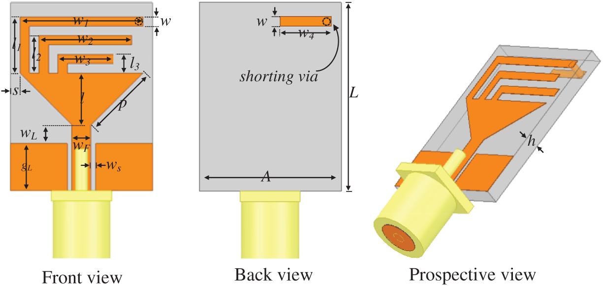
Figure 1: Schematics of the tri-band antenna
Here,
where
The reflection coefficient (|S11| values) of each antenna involved in the final design is also plotted for a clear understanding of the design procedure. Fig. 3a shows the |S11| plots of the initial design, i.e., of the triangular monopole alone (Antenna-1) and the monopole with straight (Antenna-2) and folded (Antenna-3) inverted-L-shaped stubs. The bandwidth of Antenna-1 ranges from 5.5 to 6.5 GHz because it is partially grounded [31]. Antennas-2 and-3 exhibit very similar performance because the stub sizes are the same, providing resonance at 2.4 GHz (range: 2.39–2.51 GHz) as well as 6 GHz. The stub length was optimized for resonance at 2.4 GHz. According to the fundamental monopole antenna theory, the length of the entire stub should be about a quarter-wavelength at the resonance frequency, i.e., 31.2 mm at 2.4 GHz. The total stub length of Antenna-3 is p + l1 + w1 + h + w4 = 7 + 6 + 13 + 1.6 + 5.4 = 33 mm, which is very close to the theoretical requirement. In Antenna-4, a quarter-wavelength stub is added to the initial stub. This adds p + lp2 + w2 = 7 + 4 + 9.8 = 20.8 mm to Antenna-3, for additional resonance at 3.5 GHz (Fig. 3b). Thus, the stubs allow current to follow several paths, explaining the multiband behavior [32].
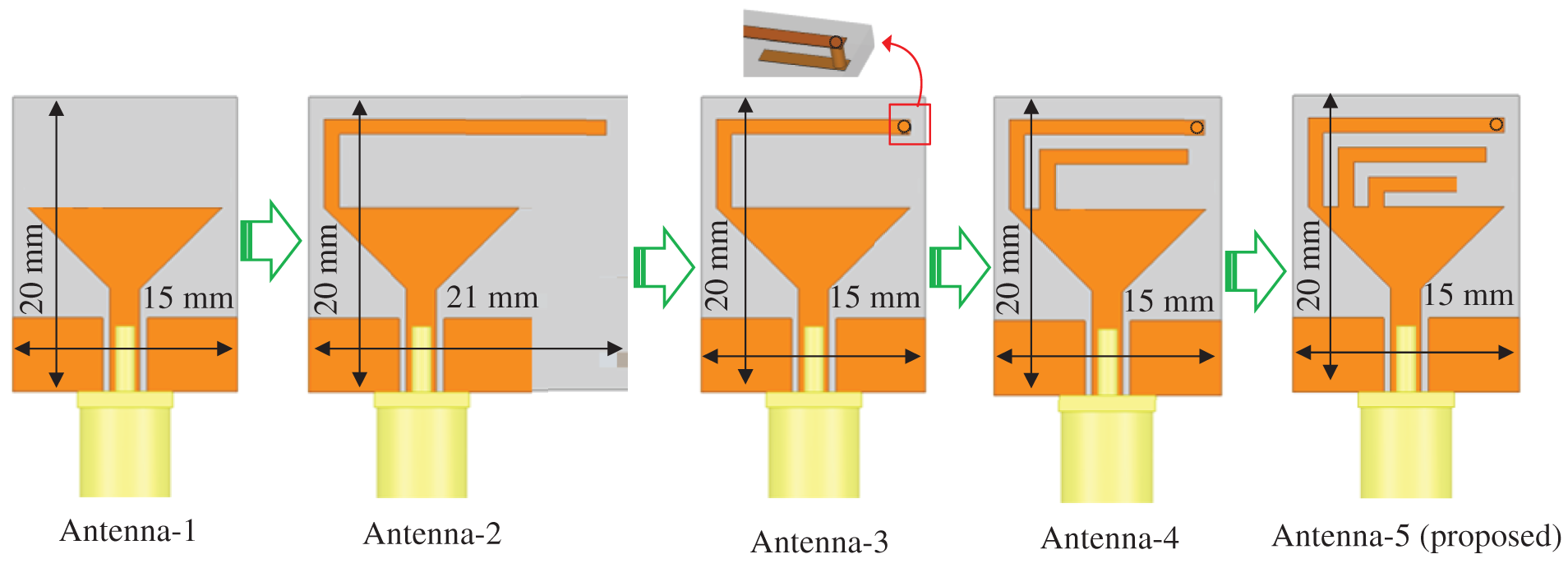
Figure 2: Design evolution of the proposed tri-band antenna
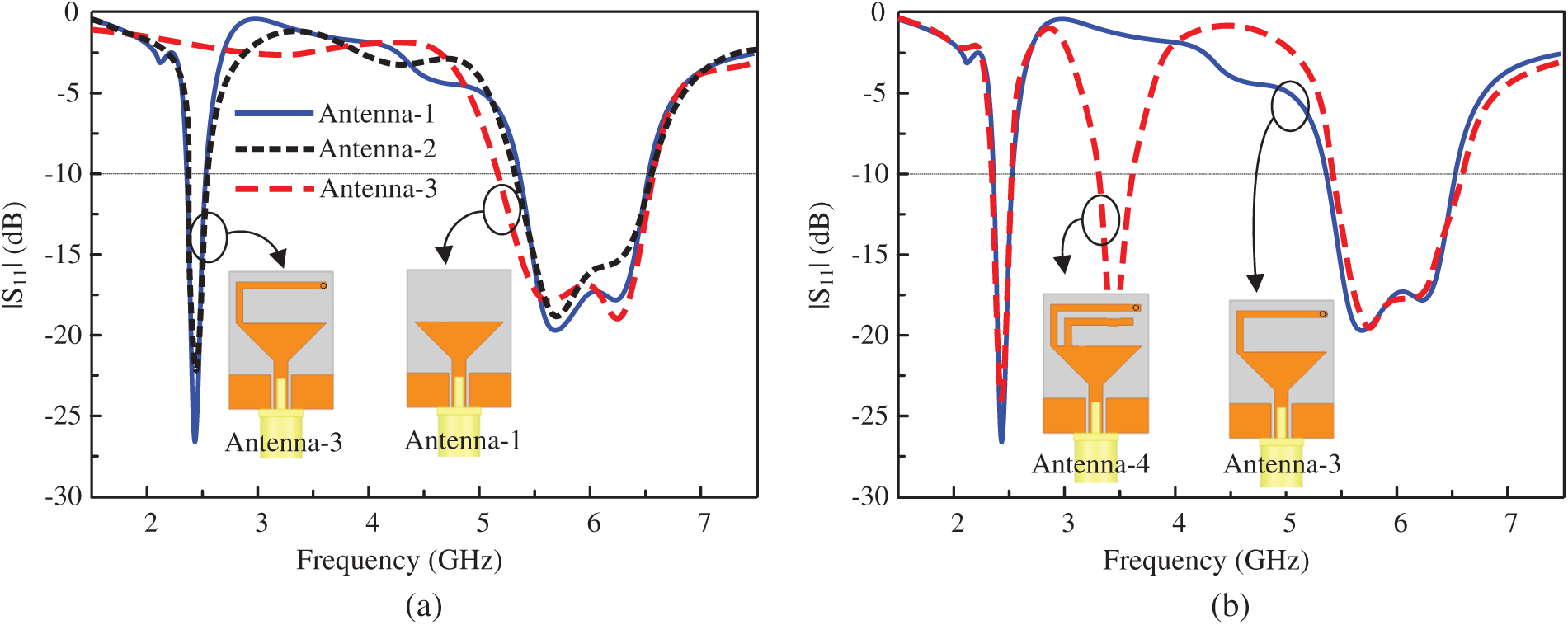
Figure 3: |S11| characteristics: comparison of (a) Antennas-1,-2, and-3, and of (b) Antennas-3 and-4
Similarly, another inverted-L stub was added to generate an additional band at 5 GHz [Antenna-5 (proposed antenna) in Fig. 4]. The 5 and 6 GHz bands deliberately overlap to provide the required ultrawide bandwidth (4.6–6.4 GHz) for the WLAN band.
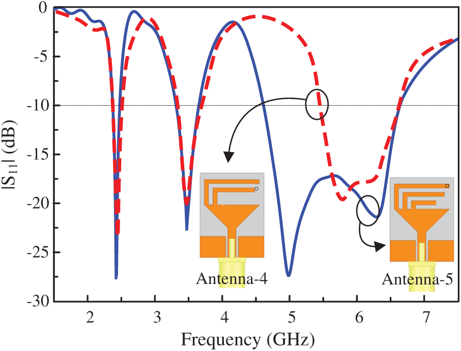
Figure 4: |S11| characteristics of the Antenna-4 and-5 (proposed antenna)
Importantly, we can tune the operating frequency by varying stub length. Resonance shifts to low frequencies when stub length is increased. Operating frequency can be increased according to user requirements by reducing the stub length. This can be understood by examining the |S11| characteristics of the final design with various values of w4 and w2 (Fig. 5).
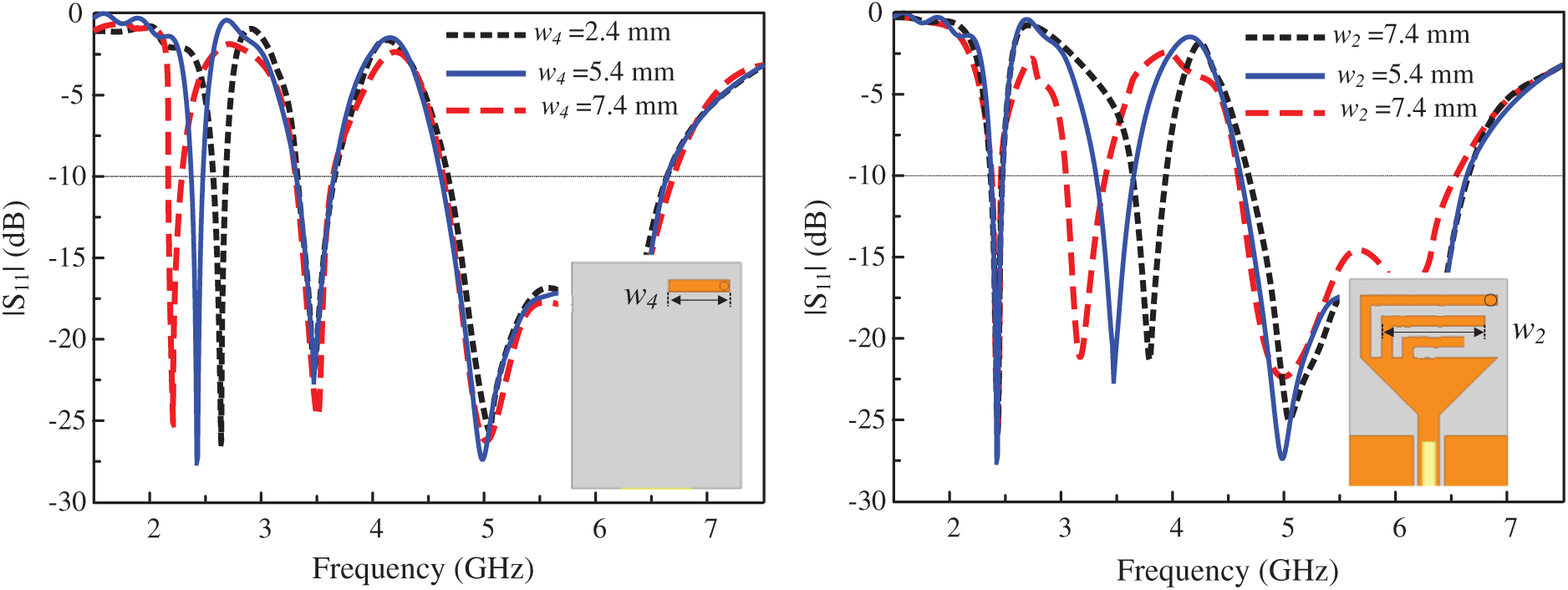
Figure 5: |S11| characteristics of the tri-band antenna at various values of (a) w4 and (b) w2
To explain the radiation mechanism, the surface current densities at the resonance frequencies are plotted in Fig. 6. At 2.4 GHz, the current is mainly in stub-1, but is distributed around stub-2 at 3.5 GHz. As predicted, the current is in stub-3 at 5 GHz. Thus, the compact antenna operating on demand at 2.4, 3.5, and 5.5 GHz enables RFID, Bluetooth, WiMAX, and WLAN band applications.
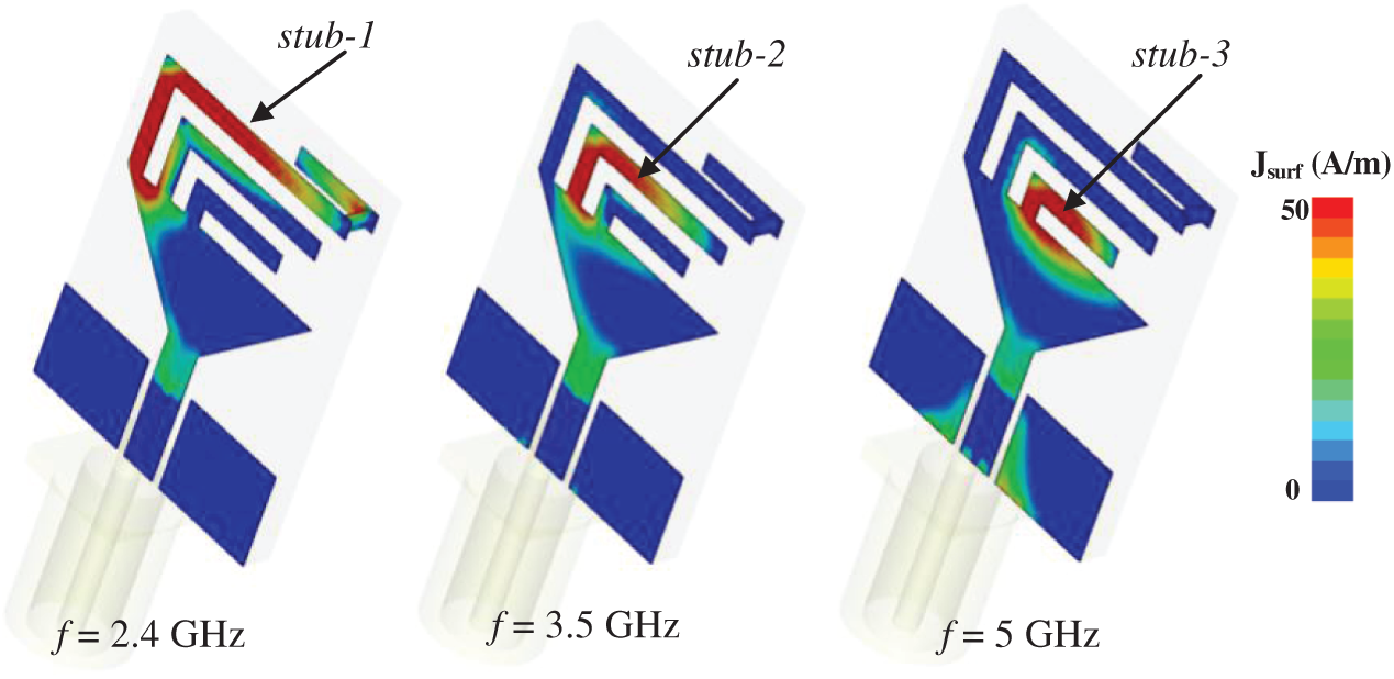
Figure 6: |S11| Surface current distributions of the antenna at various resonance frequencies
We used standard photolithography to fabricate a prototype of the antenna and measured its performance (Fig. 7). The antenna is very compact and can be easily embedded in small devices, such as USB dongles. The |S11| values were measured using an E5071C network analyzer (Agilent, Santa Clara, CA, USA), and far-field data were obtained with the antenna in an anechoic chamber.
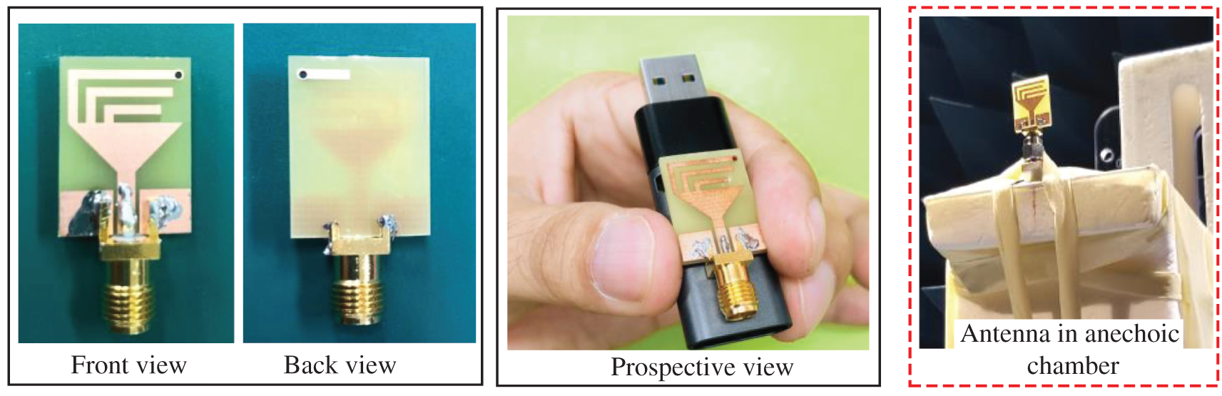
Figure 7: Photographs of the fabricated prototype
Fig. 8 shows the simulated and measured |S11| plots. The measurements are in good agreement with the simulations. The antenna resonates at three bands: 2.4 (2.38–2.51), 3.5 (3.34–3.71), and 5.5 (4.6–6.4) GHz, and impedance matching is good.
The simulated and measured gains plotted as well as the simulated radiation efficiency as a function of frequency, are shown in Fig. 9. The antenna exhibits a minimum measured gain of 1.8 dBi at the lowest resonance (2.4 GHz), 2.9 dBi in the middle band (3.5 GHz), and 4 dBi in the upper band (5.5 GHz). In contrast, the gain decreases to −3.9 dBi in the stop-bands, validating gain suppression at out-of-band frequencies. In general, the gain increases in the pass-band with the increasing frequency due to the increased effective size of the antenna [33,34]. Similarly, the antenna shows a high radiation efficiency (up to 88%) at resonating bands, while it is reduced to 40% at out-of-band frequencies.
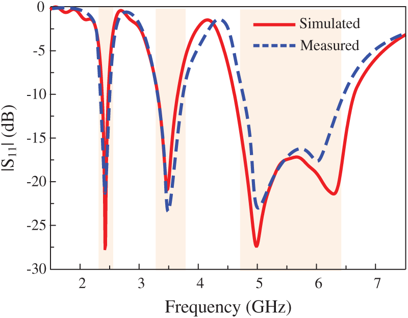
Figure 8: Simulated and measured |S11| values of the proposed antenna
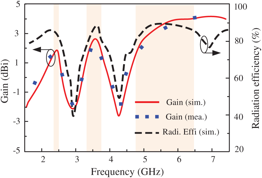
Figure 9: Gain and radiation efficiency of the proposed antenna
The radiation patterns at 2.4, 3.5, 5, and 6 GHz are shown in Fig. 10. The antenna exhibits omnidirectional radiation in the H-plane and bidirectional radiation in the E-plane. These patterns are stable at all frequencies; this is a particular strength of the design.
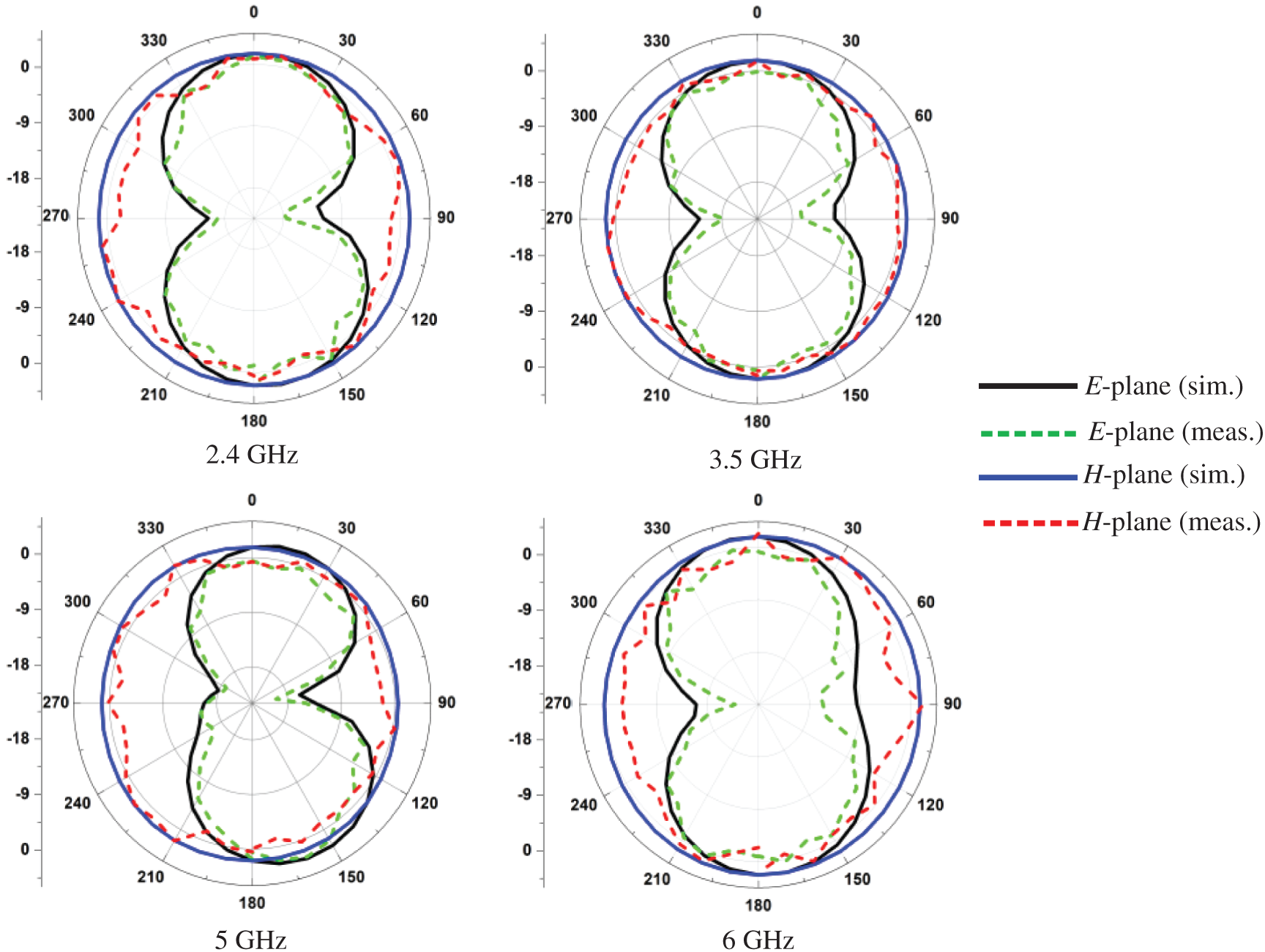
Figure 10: Simulated and measured radiation patterns at different resonating frequencies
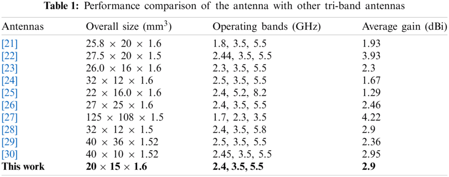
The performance of our antenna, in terms of size, operating bands, and average gain, is compared to those of state-of-the-art tri-band antennas [21–30] in Tab. 1. Our antenna outperforms the others in terms of size, gain, and radiation stability. The antennas in [22,27,30] have higher gains but are large in size. Our antenna is simple, and the operating frequency bands can be tuned as required. The small size and good radiation characteristics reflect the careful design of inverted-L stubs on a triangular monopole.
We designed and built a tri-band monopole antenna based on inverted-L shaped stubs. Multiband behavior was achieved by connecting stubs of various lengths to the upper side of a triangular monopole. The antenna was fabricated on a low-cost, commercial 1.6-mm-thick FR-4 substrate. The measurements validated the computed results. The antenna is small (20 × 15 × 1.6 mm3), and exhibits good impedance matching and gain/radiation patterns. The bandwidths allow operation at 2.4 (2.37–2.51), 3.5 (3.34–3.71), and 5.5 (4.6–6.4) GHz.
Funding Statement: This work was supported by the ICT R&D program of MSIT/IITP, [2019-0-00102, A Study on Public Health and Safety in a Complex EMF Environment]. This work was also supported by the National Radio ResearchAgency, [Rapid measurement system for new technologyantenna].
Conflicts of Interest: The authors declare that they have no conflicts of interest to report regarding the present study.
1. E. H. Lim and K. W. Leung, “Compact multifunctional antennas in microwave wireless systems,” in Compact Multifunctional Antennas for Wireless Systems. Hoboken, NJ, USA: John Wiley & Sons, pp. 1–28, 2012. [Google Scholar]
2. D. K. Naji, “Miniature slotted semi-circular dual-band antenna for WiMAX and WLAN applications,” Journal of Electromagnetic Engineering and Science, vol. 20, no. 2, pp. 115–124, 2020. [Google Scholar]
3. T. Ali, M. M. Khaleeq and R. C. Biradar, “A multi-band reconfigurable slot antenna for wireless applications,” AEU-International Journal of Electronics and Communications, vol. 84, no. 2, pp. 273–280, 2018. [Google Scholar]
4. S.-H. Lee and Y. Sung, “Multi-band antenna for wireless USB dongle applications,” IEEE Antennas and Wireless Propagation Letters, vol. 10, pp. 25–28, 2011. [Google Scholar]
5. I. Ahmad, H. Dildar, W. U. Khan, S. Ullah, S. Ullah et al., “Frequency reconfigurable antenna for multi standard wireless and mobile communication systems,” Computers, Materials & Continua, vol. 68, no. 2, pp. 2563–2578, 2021. [Google Scholar]
6. C. Y. Pan, C. H. Huang and T. S. Horng, “A new printed G-shaped monopole antenna for dual-band WLAN applications,” Microwave Optical Technology Letters, vol. 45, no. 4, pp. 295–297, 2005. [Google Scholar]
7. A. Haider, T. Khan, M. Rahman, B. M. Lee and H. S. Kim, “Quintuple band antenna for wireless applications with small form factor,” Computers, Materials & Continua, vol. 66, no. 3, pp. 2241–2251, 2021. [Google Scholar]
8. H. B. Kim, K. C. Hwang and Y. B. Park, “Compact stub-loaded meander line antenna for wireless USB dongle devices,” Microwave and Optical Technology Letters, vol. 52, no. 10, pp. 2279–2282, 2010. [Google Scholar]
9. S. L. Gunamony, J. B. Gnanadhas and D. E. Lawrence, “Design and investigation of a miniaturized single-layer ACS-fed dual band antenna for LTE and 5G applications,” Journal of Electromagnetic Engineering and Science, vol. 20, no. 3, pp. 213–220, 2020. [Google Scholar]
10. W. P. Lin, D. H. Yang and Z. D. Lin, “Compact dual-band planar inverted E-shaped antenna using defected ground structure,” International Journal of Antennas & Propagation, vol. 2014, no. 8, pp. 937423, 2014. [Google Scholar]
11. R. Patel, A. Desai and T. Upadhyaya, “An electrically small antenna using defected ground structure for RFID, GPS and IEEE 802.11 a/b/g/s applications,” Progress in Electromagnetic Research Letters, vol. 75, pp. 75–81, 2018. [Google Scholar]
12. J. Singh, R. Stephan and M. A. Hein, “Low-profile penta-band automotive patch antenna using horizontal stacking and corner feeding,” IEEE Access, vol. 7, pp. 74198–74205, 2019. [Google Scholar]
13. M. P. Raju, D. P. Kishore and B. T. P. Madhav, “CPW fed T-shaped wearable antenna for ISM Band, Wi-Fi, WiMAX, WLAN and fixed satellite service applications,” Journal of Electromagnetic Engineering and Science, vol. 19, no. 2, pp. 140–146, 2019. [Google Scholar]
14. J. H. Lu and B.-J. Huang, “Planar multi-band monopole antenna with L-shaped parasitic strip for WiMAX application,” Electronic Letters, vol. 47, no. 12, pp. 671–672, 2010. [Google Scholar]
15. S. Khan, X. C. Ren, H. Ali, C. Tanougast, A. Rauf et al., “Reconfigurable compact wide-band circularly polarised dielectric resonator antenna for wireless applications,” Computers, Materials & Continua, vol. 68, no. 2, pp. 2095–2109, 2021. [Google Scholar]
16. A. Ambika, C. Tharini and M. T. Ali, “Novel D SRR-based dual band antenna for WiMAX/C applications,” Microwave and Optical Technology Letters, vol. 61, no. 2, pp. 309–315, 2019. [Google Scholar]
17. Y. Xie, F. Chen and J. Qian, “Design of integrated duplexing and multi-band filtering slot antennas,” IEEE Access, vol. 8, pp. 126119–126126, 2020. [Google Scholar]
18. R. K. Saraswat and M. Kumar, “A metamaterial hepta-band antenna for wireless applications with specific absorption rate reduction,” International Journal of RF and Microwave Computer-Aided Engineering, vol. 29, no. 10, pp. 21824, 2019. [Google Scholar]
19. D. A. Sehrai, F. Muhammad, S. H. Kiani, Z. H. Abbas, M. Tufail et al., “Gain-enhanced metamaterial based antenna for 5G communication standards,” Computers, Materials & Continua, vol. 64, no. 3, pp. 1587–1599, 2020. [Google Scholar]
20. R. Sahoo and D. Vakula, “Compact metamaterial inspired conformal dual-band antenna loaded with meander lines and fractal shaped inductor for Wi-Fi and WiMAX applications,” IET Microwaves, Antennas & Propagation, vol. 13, no. 13, pp. 2349–2359, 2019. [Google Scholar]
21. C. V. A. Kumar, B. Paul and P. Mohanan, “Compact triband dual F-shaped antenna for DCS/WiMAX /WLAN applications,” Progress In Electromagnetics Research Letters, vol. 78, pp. 97–104, 2018. [Google Scholar]
22. H. Ahmad, W. Zaman, S. Bashir and M. Rahman, “Compact triband slotted printed monopole antenna for WLAN and WiMAX applications,” International Journal of RF and Microwave Computer-Aided Engineering, vol. 30, no. 1, pp. 21986, 2020. [Google Scholar]
23. P. V. Naidu, A. Kumar and R. Rengasamy, “Uniplanar ACS fed multi-band high-gain antenna with extended rectangular strips for portable system applications,” International Journal of RF and Microwave Computer-Aided Engineering, vol. 29, no. 10, pp. 21870, 2019. [Google Scholar]
24. L. Kang, H. Wang, X. H. Wang and X. Shi, “Compact ACS-fed monopole antenna with rectangular SRRs for tri-band operation,” Electronics Letters, vol. 50, no. 16, pp. 1112–1114, 2014. [Google Scholar]
25. R. Rajkumar and U. K. Kommuri, “A compact ACS-fed mirrored L-shaped monopole antenna with SRR loaded for multi-band operation,” Progress in Electromagnetics Research C, vol. 64, pp. 159–167, 2016. [Google Scholar]
26. V. Rajeshkumar and S. Raghavan, “A compact metamaterial inspired triple band antenna for reconfigurable WLAN/WiMAX applications,” AEU-International Journal of Electronics and Communications, vol. 69, no. 1, pp. 274–280, 2015. [Google Scholar]
27. J. Park, M. Jeong, N. Hussain, S. Rhee, P. Kim et al., “Design and fabrication of triple-band folded dipole antenna for GPS/DCS/WLAN/WiMAX applications,” Microwave and Optical Technology Letters, vol. 61, no. 5, pp. 1328–1332, 2019. [Google Scholar]
28. K. K. Naik, “Asymmetric CPW-fed SRR patch antenna for WLAN/WiMAX applications,” AEU-International Journal of Electronics and Communications, vol. 93, pp. 103–108, 2018. [Google Scholar]
29. L. Chouti, I. Messaoudene, T. A. Denidni and A. Benghalia, “Triple-band CPW-fed monopole antenna for WLAN/WiMAX applications,” Progress in Electromagnetics Research Letters, vol. 69, pp. 1–7, 2017. [Google Scholar]
30. W. Y. Chiang, C. H. Ku, C. A. Chen, L. Y. Wang, P. A. R. Abu et al., “A power-efficient multi-band planar USB dongle antenna for wireless sensor networks,” Sensors, vol. 19, no. 11, pp. 2568, 2019. [Google Scholar]
31. N. Hussain, M. Jeong, J. Park, S. Rhee, P. Kim et al., “A compact size 2.9–23.5 GHz microstrip patch antenna with WLAN band-rejection,” Microwave and Optical Technology Letters, vol. 61, no. 5, pp. 1307–1313, 2019. [Google Scholar]
32. S. H. Kiani, A. Altaf, M. Abdullah, F. Muhammad, N. Shoaib et al., “Eight element side edged framed MIMO antenna array for future 5G smart phones,” Micromachines, vol. 11, no. 11, pp. 956, 2020. [Google Scholar]
33. A. Zaidi, W. A. Awan, N. Hussain and A. Baghdad, “A wide and tri-band flexible antennas with independently controllable notch bands for sub-6-GHz communication system,” Radioengineering, vol. 29, no. 1, pp. 44–51, 2020. [Google Scholar]
34. M. U. Hassan, F. Arshad, S. I. Naqvi, Y. Amin and H. Tenhunen, “A compact flexible and frequency reconfigurable antenna for quintuple applications,” Radioengineering, vol. 26, no. 3, pp. 655–661, 2017. [Google Scholar]
 | This work is licensed under a Creative Commons Attribution 4.0 International License, which permits unrestricted use, distribution, and reproduction in any medium, provided the original work is properly cited. |