DOI:10.32604/cmc.2022.019971
| Computers, Materials & Continua DOI:10.32604/cmc.2022.019971 | |
| Article |
Controller Placement in Software Defined Internet of Things Using Optimization Algorithm
1Department of Electrical and Instrumentation Engineering, Thapar Institute of Engineering & Technology, Patiala, India
2Optical Devices and Systems, CSIR-Central Scientific Instruments Organization, Sector 30-C, Chandigarh, 160030, India
3Department of Electrical Engineering, Government Polytechnic, Ambala City, Ambala, 134003, India
*Corresponding Author: Vinod Karar. Email: vkarar@rediffmail.com
Received: 03 May 2021; Accepted: 15 July 2021
Abstract: The current and future status of the internet is represented by the upcoming Internet of Things (IoT). The internet can connect the huge amount of data, which contains lot of processing operations and efforts to transfer the pieces of information. The emerging IoT technology in which the smart ecosystem is enabled by the physical object fixed with software electronics, sensors and network connectivity. Nowadays, there are two trending technologies that take the platform i.e., Software Defined Network (SDN) and IoT (SD-IoT). The main aim of the IoT network is to connect and organize different objects with the internet, which is managed with the control panel and data panel in the SD network. The main issue and the challenging factors in this network are the increase in the delay and latency problem between the controllers. It is more significant for wide area networks, because of the large packet propagation latency and the controller placement problem is more important in every network. In the proposed work, IoT is implementing with adaptive fuzzy controller placement using the enhanced sunflower optimization (ESFO) algorithm and Pareto Optimal Controller placement tool (POCO) for the placement problem of the controller. In order to prove the efficiency of the proposed system, it is compared with other existing methods like PASIN, hybrid SD and PSO in terms of load balance, reduced number of controllers and average latency and delay. With 2 controllers, the proposed method obtains 400 miles as average latency, which is 22.2% smaller than PSO, 76.9% lesser than hybrid SD and 91.89% lesser than PASIN.
Keywords: SD-IoT; adaptive fuzzy controller; enhanced sunflower optimization (ESFO); POCO placement tool; controller placement problem; and minimum latency
Physical devices are connected to the internet with the help of Internet of Things (IoT) in which that is used to collect, share and analyze huge number of data. This concept is basic for the 2nd digital revolution and it was developed by Kevin Ashton before 17 years [1]. Generally, scalability and management problems rises due to the interconnection of large number of devices. But, it also has benefits in it. Benefits are considered as advance IoT applications like smart buildings, smart energy systems, intelligent healthcare systems and smart transport systems [2]. Moreover, another one advantage is that the devices in IoT can be connected with other devices at anytime and anywhere. Different kind of technologies like cloud computing, embedded systems, SDN and Wireless Sensor Networks (WSNs) [3]. To control the overall behavior of the network, SDN allows a central program in IoT framework and it is considered as one of the advanced technologies in IoT. Dynamic security problems, granular traffic filtering issues and security threats are quickly enabled by this controller [4].
Generally, researchers use this kind of controllers to secure computer networks by integrating SDN with IoT. So, the controllers are considered as the brain of the network and the performance of network is degraded when the controller does not work well. Proper placement of controller is required to operate the network [5]. Otherwise, some problems occurred in resource management, data routing paths and scalability properties. So, this paper concentrates on the deployment of controller in a suitable place based on the swarm intelligence concept. Because, the controller placement problem is the main issue faced in the SDN network and also the allocation of the switches to these controllers [6]. The foremost contributions of this paper are given by:
• In SD-IoT device, Adaptive Fuzzy logic controller has been designed to select the suitable location of controller and switch in a network to reduce the load balancing and propagation delay problems.
• Then, ESFO algorithm is suggested to split the network and to solve controller placement problem by selecting the controller based on a high density and minimum distance value.
• In this case, Pareto optimal controller (POCO) placement tool is used to design the controllers and nodes to perform the controller placement problem and the performance of proposed methodology is compared with existing methods by means of delay and average latency.
The rest of the paper structured is as follows, some of the related works are discussed in Section 2, Section 3 deals with the proposed methodology, and results are discussed in Section 4 and Section 5 is the conclusion.
In large area network, mobile technology is used for the network. So, Song et al. [7] proposed SD-IoT networks. It is named such a way that SDN where used to combine with IoT network. Detecting spatial events and partitioning problems over multiple flow paths were the main aim of their work. A fragmentation-based control was proposed by Kobo et al. [8] for SD wireless network reselection mechanism and efficient controller placement. It offers an efficient route for distributing the SD wireless networking control across the network. A nature inspired algorithm for load balancing in SDN was presented by Akbar Neghabi et al. [9]. Load balancing would maximize network efficiency and reliability by improving the load balancing of distribution across multiple resources. Abdelaziz et al. [10] introduced a controller for the real setting of SDN clustered with distributed controller architecture. It comprises of multiple popular SDN controllers. The proposed distributed controller had been designed by considering the parameters like packet loss and latency with reasonable CPU utilization and it's outperformed without clustering.
A new hybrid SD architecture was proposed by Lee et al. [11] for integrating IoT technologies for smart environments. To enable self-configuration and SDN infrastructure, it would be compared with an advanced optimization for the real time network. Sub-modularity optimization model was proposed in [12] to formulate different view of controller placement problem in distributed network. By means of execution time and network latency, the proposed method outperformed all the existing methods. A new routing protocol was developed in [13] to minimize the energy consumption in heterogeneous device. SDN controller was acting as a centralized manager, which provided security to the whole network. In [14], a set of heuristic algorithms were presented to minimize control traffic in SD-IoT network. These two algorithms were fast and simple heuristic algorithm which even performs better in time complexity analysis. Moreover, Density Peak Clustering (DPC) algorithm was presented in [15] to minimize the average communication latency in multi-network area. That algorithm enhanced the stability and reliability as well as improves the network performance. In that article [16], an effective system model was created using SD-IoT framework against man-in-the-middle attacks in the whole network. Additionally, that model was executed using OpenFlow protocol, Raspberry Pi, and Kodi Media center tool.
The controller placement problem is the main issue faced in the SDN network and also the allocation of the switches to these controllers. From the analysis, it is cleared that most of the controller placement problem in SD-IoT network degraded with large packet propagation latency and irregular topology of controller placement. In order to overcome these issues, this paper concentrates on the swarm intelligence-based algorithms for proper controller placement in SD-IoT network. In the last two decades, it attracts lot of researchers to use this concept in different kind of computer science applications. The swarm intelligence-based algorithms gain lot of popularity among other algorithms and they have more flexible and dynamic ability in different fields.
3 Methodology of Proposed Work
3.1 Software-Defined Network IoT
IoT can allow the combined physical and virtual objects, in which the virtual objects can only be seen in the monitor screen. This helps to provide a new opportunity for the users to contact the objects of worldwide. IoT can be implemented with a higher number of devices and users. Fig. 1 explains the basic architecture of an IoT network. It consists of four basic layers namely, the data processing layer, application layer, sensing layer, the network layer.
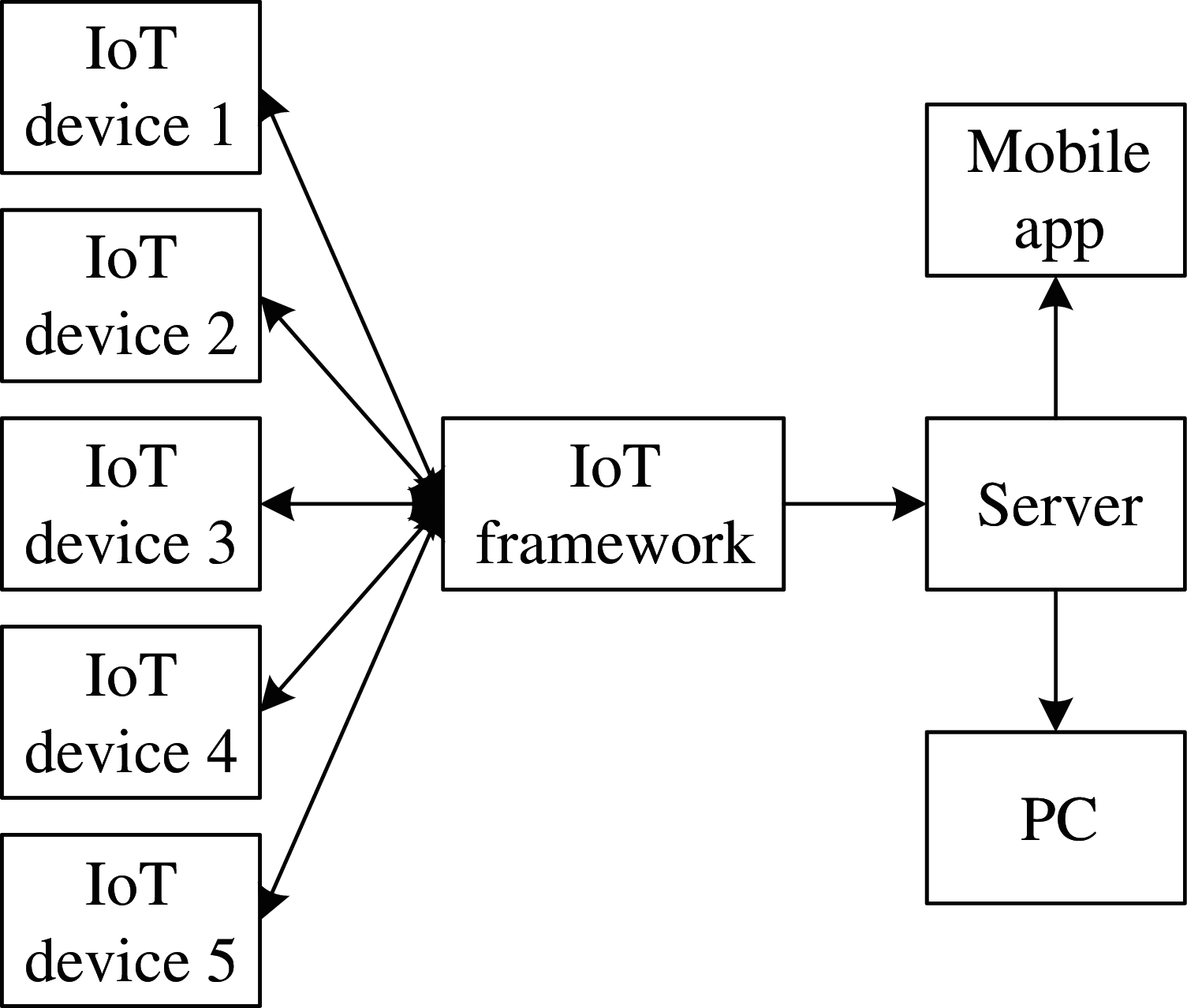
Figure 1: Simple architecture of an IoT network
In this, the different devices are connected to the IoT framework and stored all the data. The main objective of the SD-IoT network is to organize the network using the data plane and control plane and connect them over the internet. The selection of a suitable location of the controller and switch in a network for reducing the latency problem is the major challenge in the SD network [17]. Normally, controller placement leads to performance degradation as well as resilience issues. By considering these factors an adaptive fuzzy controller placement has been designed.
The communication burdens among the single controller and a larger number of forwarders increase the network delay because of the restricted control capability of a single controller. Therefore, research into an IoT aims to place multiple controllers at different locations. When deploying multiple controllers, the latency among each controller plays an important role. Also, a real network will consider the critical factor on the controller load. Accordingly, when the load of a controller reaches a threshold, the propagation latency will be increased between the controller and the node. In this concept, an optimal solution to the design of the adaptive fuzzy controller placement problem by considering the load balancing, delay constraints, failure tolerance is defined. The objective of the proposed method is to find an optimal solution to delay constraints, controller selection, and adaptive fuzzy controller placement by balancing the load and reducing the propagation latency.
The fuzzy logic system includes four stages namely, 1) the fuzzifier, 2) the knowledge base, 3) the defuzzifier, and 4) the fuzzy inference engine on fuzzy rules [18]. Then the fuzzy dynamic system can be represented by Eq. (1).
where,
The membership function is described by Eq. (2).
Defined
3.2.2 Design of Adaptive Fuzzy Control
The three steps have to be derived in this section such as adaptive laws, controller derivation and control signals. Before deriving it has to be considered the changes in the coordinates.
Let βi be the control signal, where i = {
where,
Here,
Here,
Theory 1: Under the immediate control signal βi, adaptive law
Proof:
Step 1:
The
The Lyapunov function is defined by Eq. (10).
Then,
According to young's equality [19], the following expression is obtained by Eq. (13).
Substituting Eq. (13) into Eq. (12), the expression given in Eq. (14) is obtained.
If
Here, τ1 is known as the scalar. The expression in Eq. (15) can be rewritten as Eq. (16),
By substituting the values from young's inequality and
Here,
Using Eqs. (17) and (18), the expression given in Eq. (19) is obtained.
Step 2:
Similarly,
Also, the value of
Finally,
Here,
where,
In this proposed work, ESFO is used for splitting the network and selecting the controller based on a high density and minimum distance. Pseudocode of the proposed methodology is displayed in Algorithm 1.
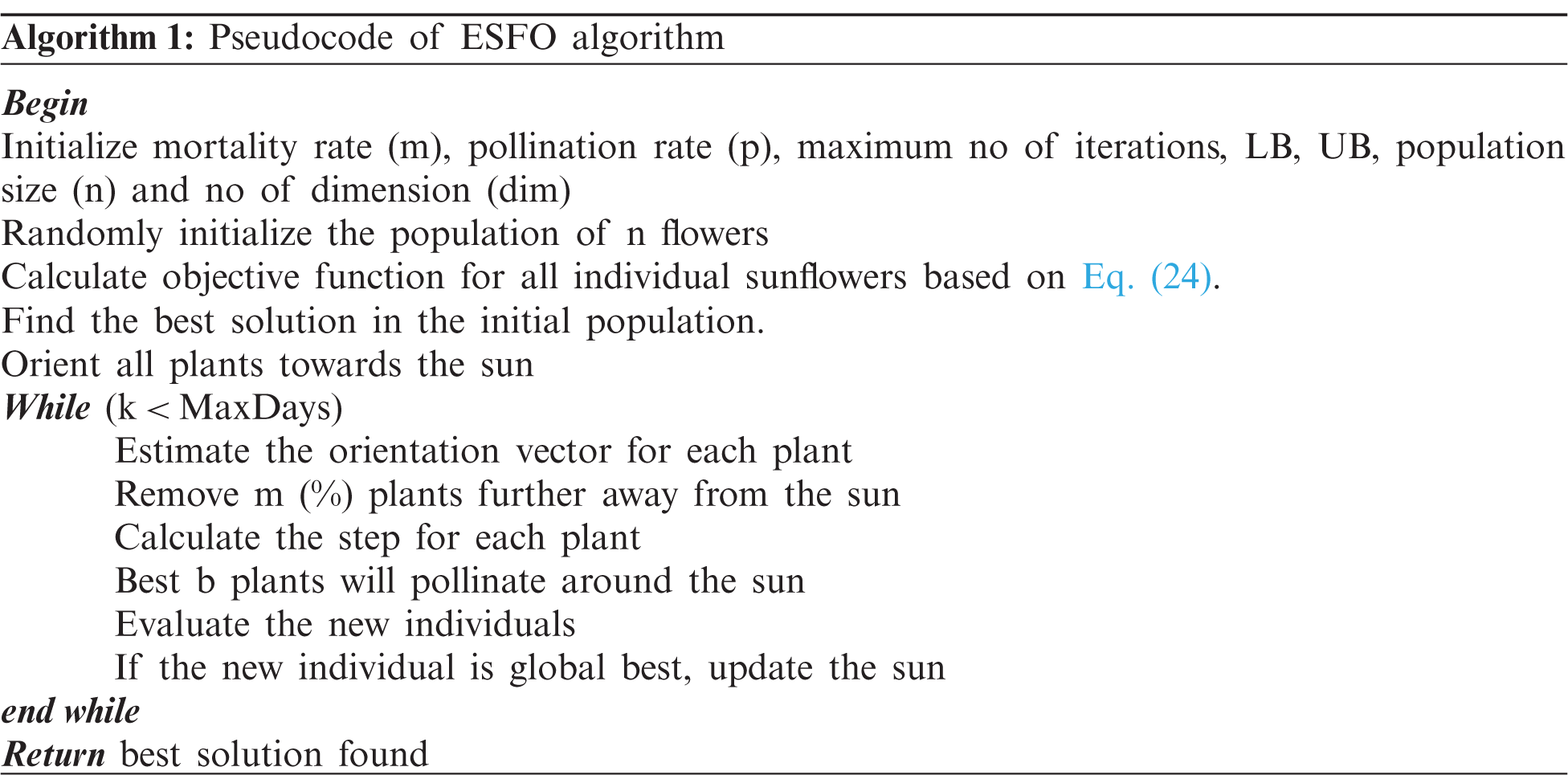
The optimized number of controllers is identified using the ESFO. The objective function can be expressed by Eq. (24).
Here, den represents the density and Dis denotes the distance to the controllers. ESFO is a population-based nature inspired algorithm. It mimics the movement of sunflower towards the sun. From the movement, there will be possibility to fertilize between the neighboring flowers closest to it. The absorbed radiation for each flower is based on the distance between it and the sun. The sun will reduce the radiation absorbed from this as the distance increasing between them [20]. This can be expressed by Eq. (25).
Here,
where,
Here,
It has to be restricted the individuals from the maximum stepping [21]. The maximum step is given by Eq. (28).
Here,
The population of the individual generation has been the starting of the algorithm and this population may be random or even. Tab. 1 shows the parameters used in the optimization algorithm. From these procedures the controller is selected with high density and minimum distance, also for splitting the network. The following section discusses the main problem in the controller placement. Flowchart of the proposed methodology is displayed in Fig. 2.
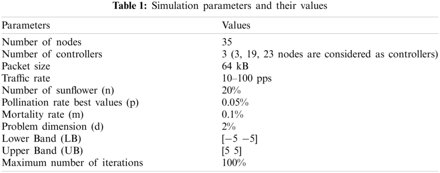
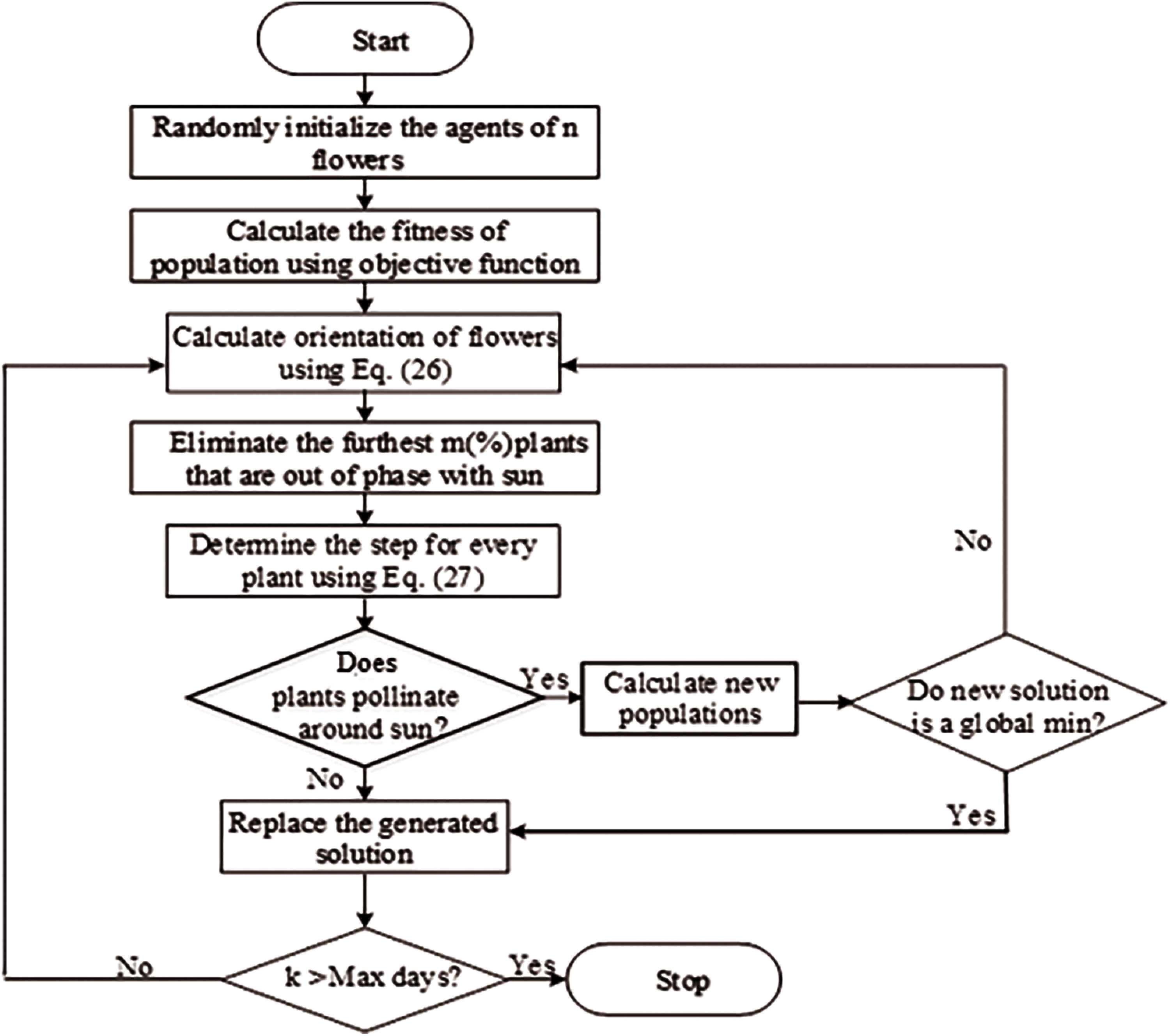
Figure 2: Flowchart of proposed ESFO algorithm
Controller placement in SD-IoT is the main issue i.e., to meet the requirement of the network it has to arrange the limited controllers. In a network, latency is an important factor to be considered and the main aim is to implement a minimum-latency placement. Certain resilience constraints have to be considered for the controller placement. For example, here it shows the searching for the best controller placement in internet2 OS3E with k = 5 controllers [22]. Different issues like latency between inter controllers, load unbalancing, failure of the controller, disruption of the network, and the controller placement problem are explained in it.
POCO placement tool can be used to calculate the optimal results and the resilience against the failure of the controller. The inclusion of resilience against controller failures are detailed below. If a controller faces a failure condition, the nodes associated with this controller are reassigned to some other controller having latency issues. Let
Here, for maximum
Let the placements
Here,
Corresponding latency can be expressed by Eq. (32).
The center of the network always gives the space for the controller as we expected. Fig. 2 shows the worst condition; i.e., if one controller failed its operation [23]. In this placement, they give the best five combinations of placement with the single controllers of k = 5. When all the controller fails expect one, thus, the maximum latency can be defined by Eq. (33).
Even in the case of
Fig. 3 indicates the latency in worst case of failure with the black points with black lines for the interconnection. In failure free case, for resilient Pareto-optimal placements that give better performance. Thus, for a selected placement it does not offer any recommendation. However, it enables the operator for choosing the placement, which returns the Pareto optimal placement. For most controllers, the shown placement results in high maximum latencies to other controllers, which might be not acceptable for certain use cases. Therefore, inter-controller latency is part of POCO's set of analyzed objectives. It is able to handle huge network instances without sacrificing much accuracy.
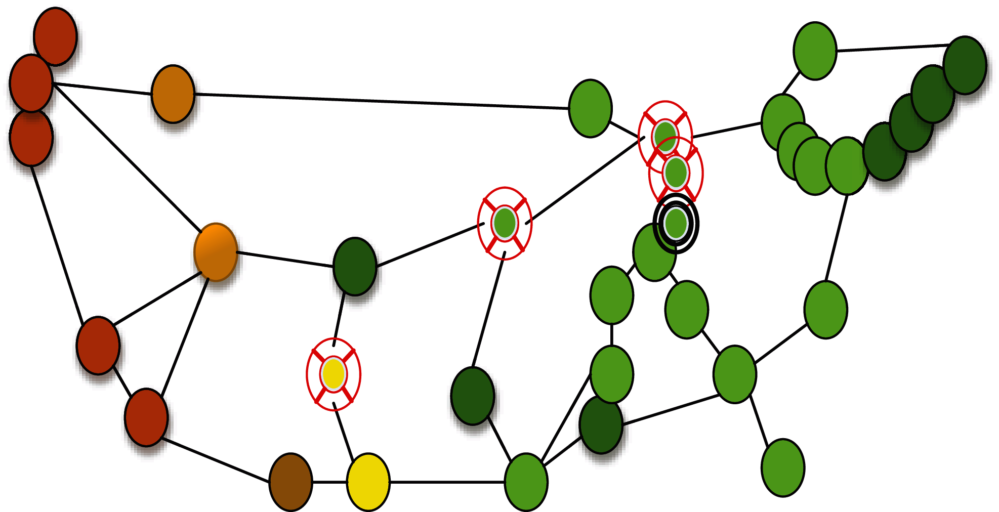
Figure 3: Latency in worst case of failure
In the case of controller-less nodes, it contains a controller for nodes always having two neighbors, which fails its operation.
Here, Maximum latency on the controller less node looking for placement with failure
In this paper, IoT is implemented with adaptive fuzzy controller placement using the enhanced sunflower optimization and POCO placement tool for the placement problem of controller. The splitting of the network is done by the sunflower optimization algorithm and the controller placement problem is solved using the Pareto optimal controller (POCO) placement tool by considering the latency and load constraints. When a controller fails, some nodes are reassigned to other controllers and experience increased latencies. To quantify the latencies in a network, we take the maximum over all node to-controller-latencies. Here, clustering is inbuilt with node failure rectification. Furthermore, load balancing is also considered along with the propagation delay metric. The MATLAB/Simulink is used to implement the IoT and comparing it with the existing technique. Tab. 1 lists the simulation parameters and their values.
Here, we considered the POCO placement tool with 35 sets of nodes and controller k = 3 (3 19 33), which are shown in Fig. 4. The nodes are represented with numbers noted in a circle and the controllers are represented by double circles. Fig. 5 represents the controller failure node with the controller misbalancing and node 6 denotes the node failure. Therefore, it faces the misbalancing condition and it affects the node from the latency problem and causes the delay operation of the network. Fig. 6 represents the controller less node operation with the controller imbalance. The color of each node, based on a traffic light color scheme, denotes the latency to the node's controller, which is selected based on the lowest distance. Here the controllers are highlighted with the double circle with number 33,19 and the controller less node is represented by 3. The proper working of the network with this controller imbalance from the maximum imbalance is explained as follows.
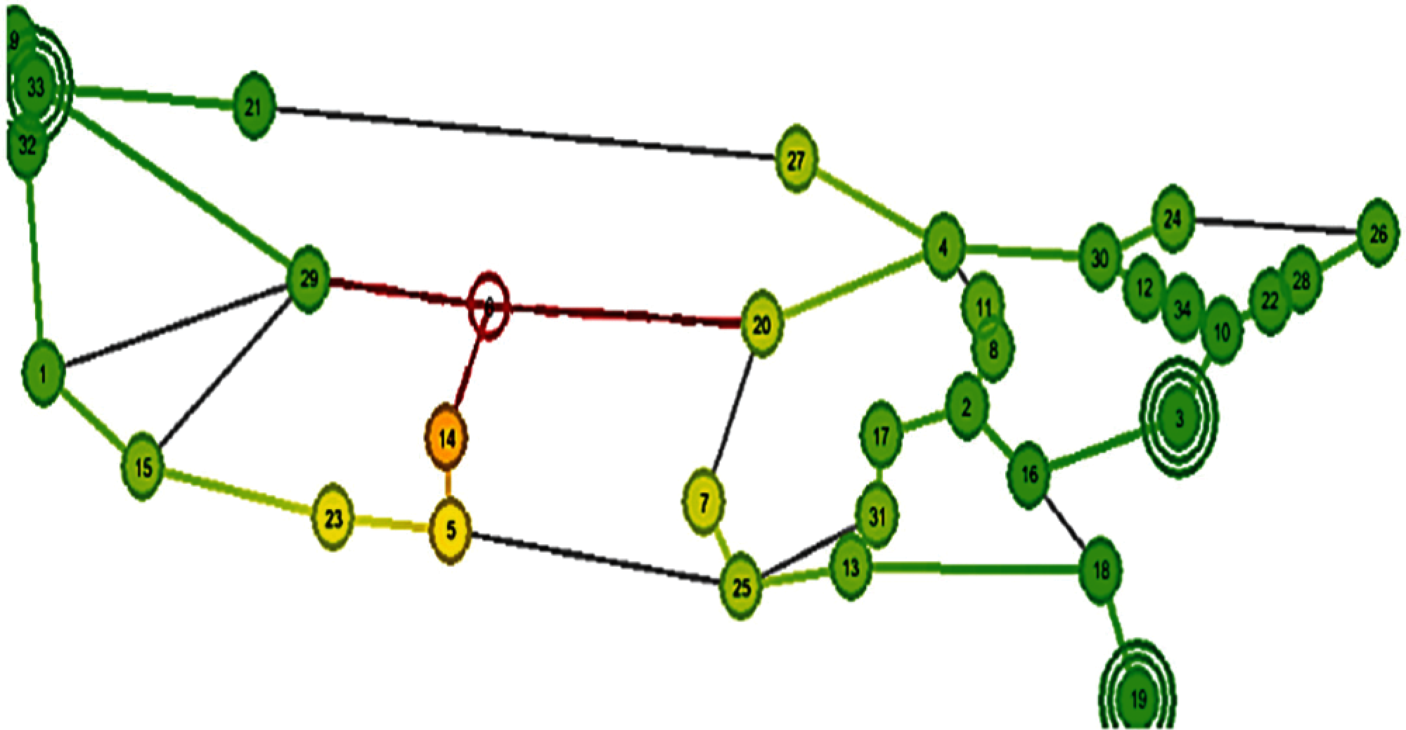
Figure 4: Controller placement with nodes
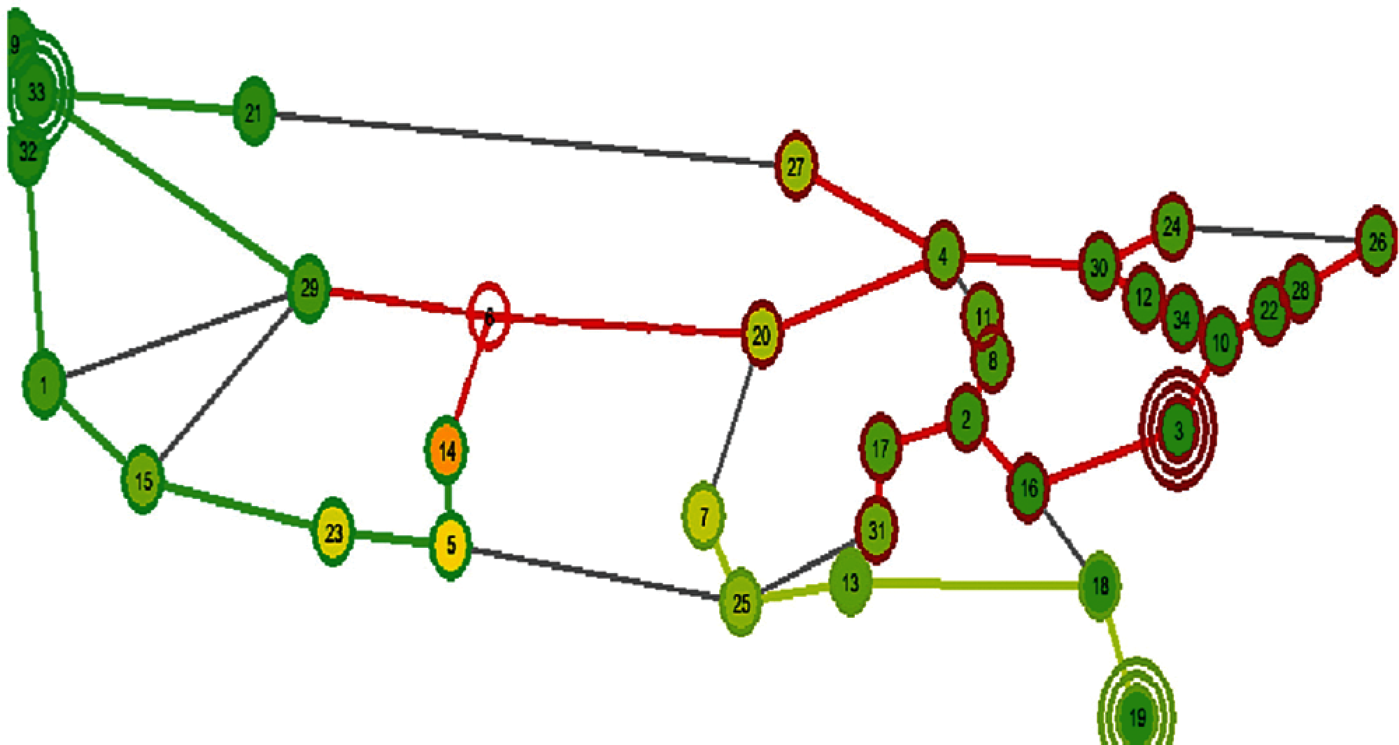
Figure 5: Node failure with controller imbalance
The controller imbalance in two cases are shown in Fig. 7, which represents the two cases also with a different number of controllers used to represent the accurate results. Fig. 7a gives the controller imbalance with the failure free operation in the y-axis with respect to the maximum controller imbalance in the x-axis. The controller imbalance is taken from node 5 to node 35 and it also shows the mean value of the maximum controller imbalance. Fig. 7a show a proper failure free condition with the controller. Fig. 7b shows the failure condition of a controller where a controller fails its operation the other will gives a proper placement. Therefore, the POCO placement tool gives a proper controller placement by considering the load balancing with a reduced latency. Tab. 2 lists the comparison analysis of delay and average latency or proposed method with existing methods.
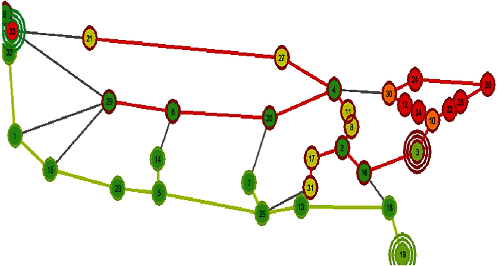
Figure 6: Controller less node operation
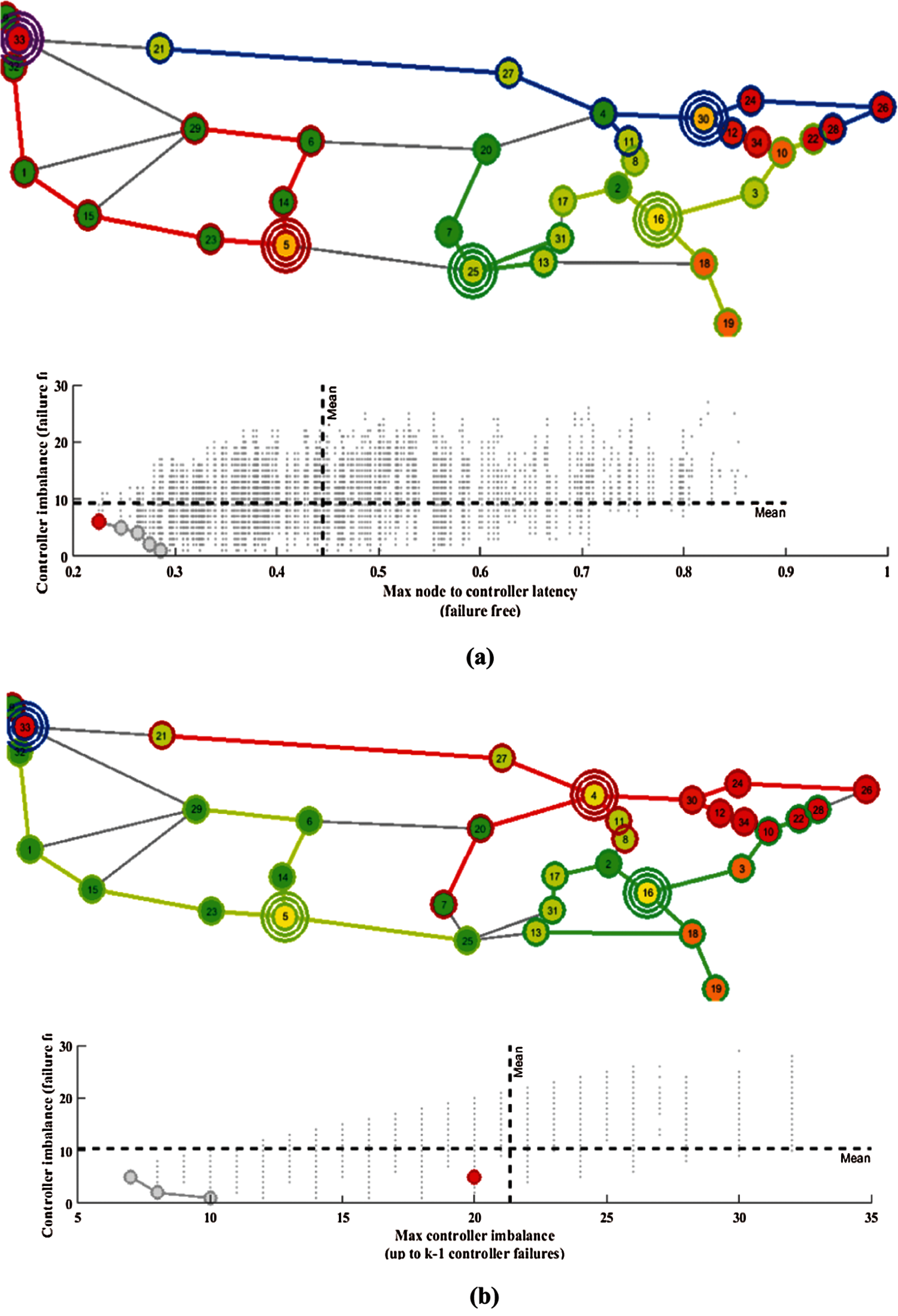
Figure 7: Controller imbalance (a) Controller imbalance with failure free conditions, (b) Contoller imbalance with a controller failure condition
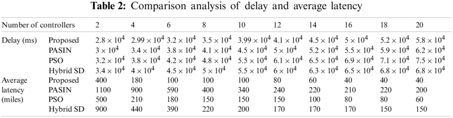
Fig. 8 represents the comparison analysis of the network based on the delay response and the average latency response by comparing it with the different recent technics. The proposed system gives a reduced latency and delay issue as compared to the existing system. Generally, as the number of controllers increases, the delay and latency value will seem to be increased for every network. Each sub topology consisting of at least two nodes that can be cut off from the entire network by at most two link- or node-failures has to be covered by at least one controller. Placing a controller in a sub topology automatically also covers all larger sub topologies that includes the smaller one. This allows to develop a procedure to calculate k for a topology without evaluating πN controller-less for all possible placements. Without this trick, the computational effort to find an optimal k could not be handled. The minimum number of controllers can be found as follows. Pareto-optimal placements that perform better in the resilient case perform worse in the failure free case and vice versa. Thus, POCO usually gives no recommendation for a particular placement, but returns the set of Pareto-optimal placements, which enables the network operators to choose the placement that fits their needs best. For our proposed system, if the number of controllers considered to be 6 and the value of delay, latency will be 3 × 10⁴ ms and 400 miles, respectively and the other existing techniques like PASIN, which mentioned in the related work, Hybrid SD [21] and PSO [24]. It will have high value of delay and latency. The latency and delay gained by the proposed system are relatively stable and volatile as compared to the others. Thus, the proposed algorithm is seemed to be the best solution for setting the minimum latency and delay issues in the SD-IoT system.
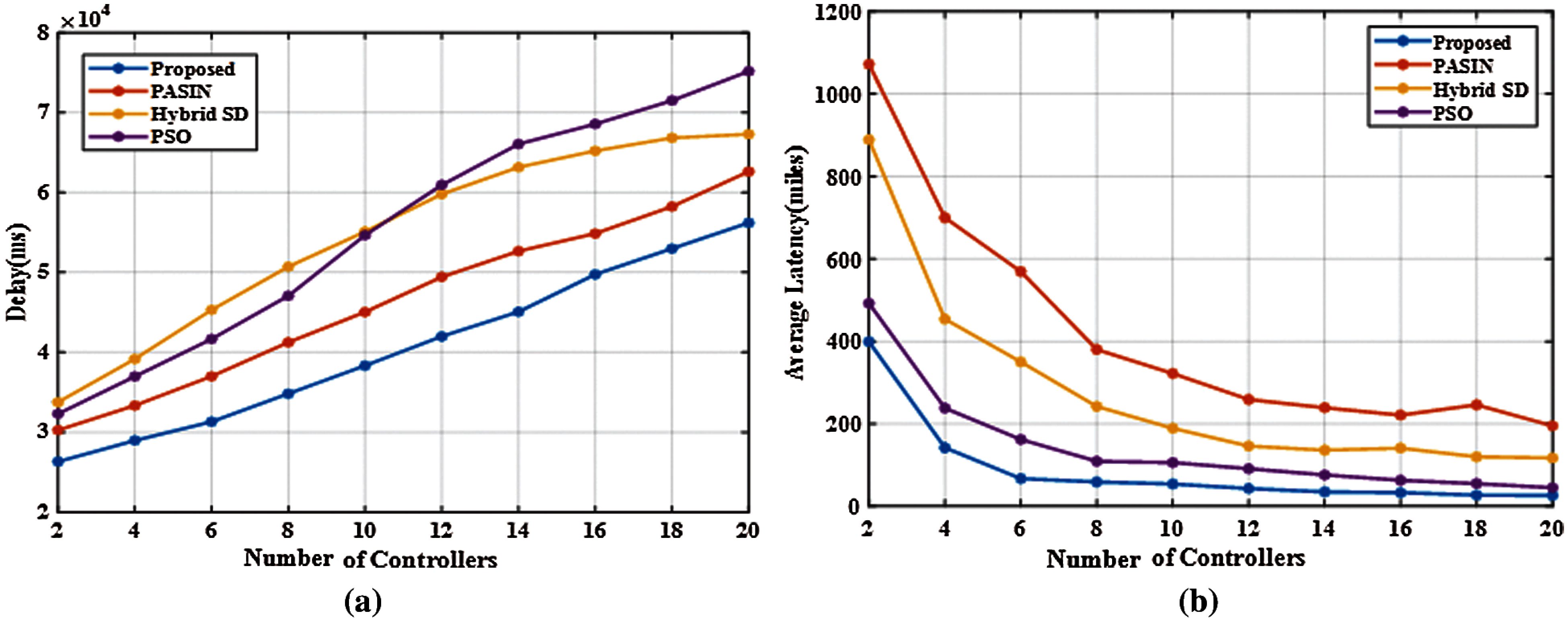
Figure 8: Comparison analysis. (a) Delay response with the number of controllers, (b) Average latency with the number of controllers
In this paper, the controller placement problem for the distributed network has been focussed, specifically for the IoT network, and the concept of optimization algorithm has been applied to solve the class of controller placement problem, which is common in real systems. Initially, an adaptive fuzzy controller concept has been utilized to find an optimal solution for controller selection in which it has balanced the load and minimized the propagation latency in whole SD-IoT network. Finally, an effective ESFO algorithm is proposed to split the network and to select the best controller based on high density and minimum distance value using POCO tool. The MATLAB/Simulink is used to implement the system and compared the proposed system with the existing techniques like PASIN, Hybrid SD and PSO. With 2 controllers, the proposed method obtains 400 miles as average latency, which is 22.2% smaller than PSO, 76.9% lesser than hybrid SD and 91.89% lesser than PASIN. In the future, we intend to test the proposed strategy in realistic scenarios and design a dynamic provision mechanism for the SDN Controller. Moreover, different performance metrics like energy consumption, and response time must be considered in the future work to improve the quality of service (QoS) in IoT networks.
Funding Statement: The authors received no specific funding for this study.
Conflicts of Interest: The authors declare that they have no conflicts of interest to report regarding the present study.
1. F. Tang, Z. M. Fadlullah, B. Mao, N. Kato, “An intelligent traffic load prediction-based adaptive channel assignment algorithm in SDN-ioT: A deep learning approach,” IEEE Internet of Things Journal, vol. 5, no. 6, pp. 5141–5154, 2021. [Google Scholar]
2. R. Krishnamurthi, A. Kumar, D. Gopinathan, A. Nayyar, B. Qureshi, “An overview of IoT sensor data processing, fusion, and analysis techniques,” Sensors, vol. 20, no. 21, pp. 6076 (1–232020. [Google Scholar]
3. S. Sennan, S. Ramasubbareddy, S. Balasubramaniyam, A. Nayyar, M. Abouhawwash, N. A. Hikal, “T2fl-pSO: Type-2 fuzzy logic-based particle swarm optimization algorithm used to maximize the lifetime of internet of things,” IEEE Access, vol. 29, no. 9, pp. 63966–63979, 2021. [Google Scholar]
4. F. Tang, B. Mao, Z. M. Fadlullah, N. Kato, “On a novel deep-learning-based intelligent partially overlapping channel assignment in SDN-ioT,” IEEE Communications Magazine, vol. 56, no. 9, pp. 80–86, 2018. [Google Scholar]
5. M. J. Islam, M. Mahin, S. Roy, B. C. Debnath, A. Khatun, “Distblacknet: A distributed secure black sdn-iot architecture with nfv implementation for smart cities,” in 2019 Int. Conf. on Electrical, Computer and Communication Engineering (ECCECox’sBazar, Bangladesh, IEEE, pp. 1–6. [Google Scholar]
6. A. Nayyar, D. N. Le, N. G. Nguyen. Advances in Swarm Intelligence for Optimizing Problems in Computer Science, New York: CRC Press, 2018. [Google Scholar]
7. C. Song, J. Wu, X. Chen, L. Shi and M. Liu, “Towards the partitioning problem in software-defined IoT networks for urban sensing,” in Int. Conf. on Pervasive Computing and Communications (PerComAthens. Greece, pp. 1–9, 2018. [Google Scholar]
8. H. I. Kobo, M. A. Abu-Mahfouz and G. P. Hancke, “Efficient controller placement and reelection mechanism in distributed control system for software defined wireless sensor networks,” Transactions on Emerging Telecommunications Technologies, vol. 30, no. 6, pp. e3588, 2019. [Google Scholar]
9. A. Akbar Neghabi, N. Jafari Navimipour, M. Hosseinzadeh and A. Rezace, “Nature-inspired meta-heuristic algorithms for solving the load balancing problem in the software-defined network,” International Journal of Communication Systems, vol. 32, no. 4. pp. e3875, 2019. [Google Scholar]
10. A. Abdelaziz, A. T. Fong, A. Gani, U. Garba, S. khan et al., “Distributed controller clustering in software defined networks,” PloS One, vol. 12, no. 4, pp. e0174715, 2017. [Google Scholar]
11. A. Lee, X. Wang, H. Nguyen and I. Ra, “A hybrid software defined networking architecture for next-generation ioTs,” KSII Transactions on Internet and Information Systems, vol. 12, no. 2, pp. 932–945, 2018. [Google Scholar]
12. A. K. Tran, M. Piran, C. Pham, “SDN controller placement in IoT networks: An optimized submodularity-based approach,” Sensors, vol. 19, no. 4, pp. 5474, 2019. [Google Scholar]
13. C. Kharkongor, T. Chithralekha, R. Varghese, “A SDN controller with energy efficient routing in the internet of things (IoT),” Procedia Computer Science, vol. 89, pp. 218–227, 2016. [Google Scholar]
14. K. Choumas, D. Giatsios, P. Flegkas, T. Korakis, “SDN controller placement and switch assignment for Low power IoT,” Electronics, vol. 9, no. 2, pp. 325, 2020. [Google Scholar]
15. X. Cui, X. Gao, Y. Ma, W. Wang, “A controller deployment scheme in 5G-ioT network based on SDN,” EURASIP Journal on Wireless Communications and Networking, vol. 248, pp. 1–19, 2020. [Google Scholar]
16. A. Al Hayajneh, M. Z. Bhuiyan, I. McAndrew, “Improving internet of things (IoT) security with software-defined networking (SDN),” Computers, vol. 9, no. 1, pp. 8(1–142020. [Google Scholar]
17. M. Cuka, D. Elmazi, M. Ikeda, K. Matsuo and L. Baroli, “Iot node selection and placement: A New approach based on fuzzy logic and genetic algorithm,” in Conf. on Complex, Intelligent, and Software Intensive Systems, Cham, Springer, pp. 22–35, 2019. [Google Scholar]
18. A. Ali, “A robust direct adaptive fuzzy control for a class of uncertain nonlinear MIMO systems,” Soft Computing, vol. 23, no. 19, pp. 9747–9759, 2019. [Google Scholar]
19. C. Wu, J. Liu, X. Jing, H. Li and L. Wu, “Adaptive fuzzy control for nonlinear networked control systems,” IEEE Transactions on Systems, Man and Cybernetics: Systems, vol. 47, no. 8, pp. 2420–2430, 2017. [Google Scholar]
20. G. F. Gomes, S. S. da Cunha and A. C. Ancelotti, “A sunflower optimization (SFO) algorithm applied to damage identification on laminated composite plates,” Engineering with Computers, vol. 35, no. 2, pp. 619–626, 2019. [Google Scholar]
21. M. H. Qais, H. M. Hasanien and S. Alghuwainem, “identification of electrical parameters for three-diode photovoltaic model using analytical and sunflower optimization algorithm,” Applied Energy, vol. 250, pp. 109–117, 2019. [Google Scholar]
22. S. Lange, S. Gebert, T. Zinner, P. Tran-Gia, D. Hock et al., “Heuristic approaches to the controller placement problem in large scale SDN networks,” IEEE Transactions on Network and Service Management, vol. 12, no. 1, pp. 4–17, 2015. [Google Scholar]
23. D. Hock, M. Hartmann, G. Gebert, M. Jarschel, T. Zinner et al., “Pareto-optimal resilient controller placement in SDN-based core networks,” in Proc. of the 2013 25th Int. Tele Traffic Congress (ITCShanghai, China, pp. 1–9, 2013. [Google Scholar]
24. C. Gao, H. Wang, F. Zhu, L. Zhai, S. Yi et al., “A particle swarm optimization algorithm for controller placement problem in software defined network,” in Int. Conf. on Algorithms and Architectures for Parallel Processing, Cham, Springer, pp. 44–54, 2015. [Google Scholar]
 | This work is licensed under a Creative Commons Attribution 4.0 International License, which permits unrestricted use, distribution, and reproduction in any medium, provided the original work is properly cited. |