DOI:10.32604/cmc.2022.020775
| Computers, Materials & Continua DOI:10.32604/cmc.2022.020775 | |
| Article |
A Hybrid Model for Reliability Aware and Energy-Efficiency in Multicore Systems
1Department of Computer and Systems Engineering, Faculty of Engineering, Helwan University, Cairo, 11792, Egypt
2Egyptian Computer Emergency Readiness Team (EG-CERT), National Telecom Regulatory Authority (NTRA), Cairo, 12577, Egypt
*Corresponding Author: Samar Nour. Email: samar_nour@h-eng.helwan.edu.eg
Received: 07 June 2021; Accepted: 15 July 2021
Abstract: Recently, Multicore systems use Dynamic Voltage/Frequency Scaling (DV/FS) technology to allow the cores to operate with various voltage and/or frequencies than other cores to save power and enhance the performance. In this paper, an effective and reliable hybrid model to reduce the energy and makespan in multicore systems is proposed. The proposed hybrid model enhances and integrates the greedy approach with dynamic programming to achieve optimal Voltage/Frequency (Vmin/F) levels. Then, the allocation process is applied based on the available workloads. The hybrid model consists of three stages. The first stage gets the optimum safe voltage while the second stage sets the level of energy efficiency, and finally, the third is the allocation stage. Experimental results on various benchmarks show that the proposed model can generate optimal solutions to save energy while minimizing the makespan penalty. Comparisons with other competitive algorithms show that the proposed model provides on average 48% improvements in energy-saving and achieves an 18% reduction in computation time while ensuring a high degree of system reliability.
Keywords: Energy-efficiency; safe voltage; multicore processors; core utilization; dynamic voltage/frequency scaling; makespan
To process a massive amount of data, a possible solution is to use a large multicore system. The energy consumption of such multicore systems is increasingly rising. This leads to an increase in cooling costs and reduces the reliability of the system components. In order to work efficiently, the power consumption and time limitations of multicore system chips become more important as the number of cores in a single chip is rising up. In multicore systems, the power consumption is either static or dynamic. Dynamic Voltage/Frequency Scaling (DV/FS) is one of the major techniques used to manage a system’s power consumption. This technique can provide substantial power saving with a small performance loss if exists. The DV/FS strategy centered on detecting idleness in a device to scale down the frequency and optimize savings in energy to achieve minimal output costs because of the dependence between power consumption and voltage frequency. The Dynamic Power Management (DPM) approach [1] is used to determine a specific point in which the core is switched into a sleep mode to decrease the leakage current, which leads to a decrease in its static power. The power management points should carefully be chosen to decrease the overall energy consumption. In [2], a hybrid between DV/FS and DPM approaches is proposed. The DV/FS scheduling problem can be used to determine the optimum execution frequency for each core [3]. While greedy techniques predict local optimal Vmin/F levels to each core [4]. In [5], a heuristic approach is introduced which uses the Dynamic Programming (DP) technique to speed up the DV/FS run-time. At the final stage, a DP technique moves backward, through the sub-problems solutions, stage by stage to obtain the optimal solution. The DP used overlapping sub-problems, which can be solved in parallel through multicores. In this context, this approach can achieve global optimal levels by considering the advantage of core utilization and energy efficiency. In Boudjadar [6] built schedules with the purpose of reducing the processing energy with high utilization levels for the cores. However, there will be a performance degradation due to the increase in memory access requests, which in turn increases the accumulated waiting time to access DRAM. It should be noted that core utilization is considered a key parameter in predicting the optimal Vmin/F levels. In Papadimitriou et al. [7] is used the Voltage Guard Bands of multicore chips to achieve rapid energy conservations. Where the discrepancy between a chip’s real Vmin and the nominal operating voltage acts as a protected guard band for any application. Therefore, the voltage settings can be modified to function correctly. In this paper, a hybrid model for reliability-aware scheduling and energy efficiency in multicore systems is proposed. The proposed model introduces a mixture between dynamic programming and greedy technique to achieve optimal Voltage/Frequency (Vmin/F) levels.
This model is composed of three stages. The first stage named the safe voltage stage that gets the optimum safe voltage (Vmin) of the system, while the second stage named set the level of energy efficiency stage which predicts the optimum Vmin/F levels to each core using greedy techniques, and eventually, the third stage named allocation stage to assess the global optimal allocation for workloads using dynamic programming.
This paper summarizes the major contributions as follows: Firstly, we propose a novel energy and reliability-aware scheduling model that globally optimized the distribution of tasks to cores or clusters in an efficient manner. Secondly, the proposed model gets the optimum frequency levels for individual core or cluster, leading to minimizing makespan execution time. Thirdly, the proposed model achieved the highest load balance in addition to the best utilization levels in different workloads. Finally, we evaluate the optimal energy-efficient model using several benchmarks to examine the performance and reliability of the proposed model through multicore systems.
This paper has the following structure. Section 2 presents a summary of the related algorithms. Section 3 demonstrates the system model. Section 4 describes the proposed hybrid model and its stages. Section 5 explores a detailed explanation of status settings, platform, experimented workloads, simulation methods, and results. In section 6 discusses the conclusions and the future direction.
Many optimization algorithms were proposed for the balancing of power/energy consumption and time of execution include linear programming [4], genetic algorithms [8], game theory [9], and machine learning techniques [10]. From the huge amount DV/FS is used on homogeneous multicore systems where device levels that are more specifically applicable to the scope of this work are allocated to (per-core DV/FS) or each core group (voltage and frequency island) [2]. In this paper, we will use the previous two methods (per-core DV/FS) and (voltage and frequency island) at the same time. Many studies investigated the reliability of heterogeneous systems like [11] to control power systems, also the idea of Smart Energy and Reliability Conscious Scheduling algorithm has been suggested (SERAS). It consists of three stages, which maps work tasks to multi-skilled nodes with the purpose of completing workloads as effectively as possible while still meeting the reliability needs. While [12] analysis, both the equity and the energy efficiency of heterogeneous multi-core processors (HMPs). This article proposes a heterogeneous fairness-aware energy efficient framework (HFEE) architecture that uses DV/FS for fairness constraints and energy efficiency calendar. A true heterogeneous multicore systems is used and tested in the proposed framework. The proposed a hybrid model is compared with [12]. We achieved more saving in energy, which is presented in the results section. The event control is used only to increase system performance and reduce overhead power consumption when a temperature boundary or timeout has been exceeded. Reference [13] Formulate an issue about voltage scheduling that reduces device power requirements to a minimum and solves them in polynomial time by using exact dynamic programming (DP).
This section introduces a hybrid model for reliability-aware scheduling and energy efficiency in multicore systems. The proposed model is composed of three stages. The first stage gets the optimum safe voltage (Vmin) of the system, while the second stage predicts the optimum Vmin/F for each core using the greedy technique, and eventually, the third stage assesses the optimal allocation for workloads through dynamic programming. Fig. 1 presents the proposed hybrid model. As shown, the proposed model is constructed from three stages having four modules named task module, architecture module, power module, and failure and reliability module. This gives a clear explanation for the energy-efficient scheduling problem. For this purpose, we demonstrate each stage in the following subsections.
In this stage, a few sets of measurements are conducted to determine the state of each core. It is possible to consider current voltage from the core remains steady even at a safe voltage (Vmin). The detailed function for each module in this stage will be described as follows.
In the task module, the tasks are multithreaded benchmarks. Based on the existing memory system architecture, the cores access a shared memory such as (L2 cache or main memory) to allow inter-core data traffic at runtime. In this model, input tasks are distributed among cores. Each core executes application programs to process a particular subset of tasks in parallel with other cores. The underlying architecture provides shared memory for communicating data between cores during benchmark execution. It is noticed that memory access delays arise from accessing the data via shared memory. These delays, which are known as communication delays. Assume that [W1, W2, W3 … Wn] are the workloads in a job pool. It should be noted that the workloads deal with various programming functions. Therefore, these workloads require different amounts of time to compute on one or more processing elements (cores). On the other hand, tasks could be classified as (CPU, Memory access) according to the number of instructions per second (IPS) added to the number of memory access. It should be noted that tasks are assumed to be non-preemptive. It is essential to obtain task utilization before applying the proposed model. In this module each task (Ti) has (Ui; Vmin; and Fi), where Ui is task utilization, Vmin is safe voltage and Fi is the selected frequency.

Figure 1: The proposed hybrid model for reliability aware scheduling and energy-efficiency
The architecture of the proposed module is demonstrated in Fig. 2. As shown the proposed module contains individual cores which can be combined to perform efficiently based on workload requirements. In this paper, two clusters are built, the first cluster with a low frequency (fl) to run the memory task while the second cluster with high frequency (fh) to run the CPU task. According to a hybrid model, there is a free core that executes any class of task (Memory or CPU) with different frequencies as depicted in Fig. 2.

Figure 2: The proposed architecture module
3.2 Optimal Energy Level Stage
This stage introduces the proposed scheduler that ensures each job has the optimal Vmin/F level. It should be noted that the preceding task and architecture modules are used incorporated with the following modules as follows:
The power usage of the silicon-based CMOS processor is based on the aggregation of static and dynamic powers as in Eq. (1).
where Pstatic is the static power and is also referred to as the leakage power.
where V is the supply voltage and Ileak is the leakage current which is independent of the actual frequency and the system activity. The static power is approximately proportional to the leakage current. As a consequence, switching a processor to a sleep mode will decrease the Ileak. This leads to a decrease in Pstatic and eventually the overall power dissipation decreases. Therefore, the DPM approach is adopted to determine the sleep mode switching time for a core with a guarantee that no task misses its deadline. While Pdynamic is the dynamic power that is consumed during the task’s execution time [1].
where C is a constant, V is the supply voltage, and F is the operating frequency. The value of dynamic power is directly proportional to the frequency. As a consequence, the decrease of a processor frequency will to a reduction in the overall Pdynamic. Therefore, the DV/FS approach is used for task scheduling where the decrease in the processor’s frequency contributes to an increase in task execution time, and again. This aspect should be considered carefully to avoid missing a task deadline.
The energy consumed by processing a single task Ti at Vmin and frequency Fi (denoted by Ei) as in Eq. (4).
where ti the execution time of the task. The total energy consumed by all the tasks, as in Eq. (5).
where Eijk denotes the energy consumed by task Ti when executed on Core Cj at a frequency level Fk. The total execution time (makespan) by all the tasks, as in Eq. (6).
where Tijk is the total execution time to get optimum Vmin/F by task Ti when executed on Core Cj at a frequency level Fk.
3.2.2 Failure and Reliability Module
Fault tolerance methods can typically be divided into two categories: active and passive redundancy methods. Active methods of redundancy use fault detection to improve system reliability [14]. The standby-sparing method is one of the most common active redundancy methods [15]. When a failure in the primary unit occurs, the execution is changed to the replacement unit in the standby-sparing system [16]. Three options for assigning primary and replacement units are available. These options include hot standby sparing (HSS), cold standby sparing (CSS), and warm standby saving (WSS) [16]. The primary unit in addition to the replacement unit is both configured in the HSS system. Such that any input in the main unit is also provided to the replacement unit. If the primary device fails, the replacement devices start to perform tasks immediately. However, the CSS method does not support the replacement device until the primary unit is failing and the replacement device begins to run the task [16]. The speed of switching between main and replacement units is longer in the CSS system than in the HSS method. The WSS named (de-energized state) method is much like the HSS method, but it performs the first part of the tasks and leaves the part causing retard. On the other hand, passive approaches, however, use techniques of fault masking [16]. The most common passive redundancy techniques are the NMR and task replication. To achieve the reliability goal, NMR’s and task replication processes are used redundant hardware to withstand failures and software replicas. In the task replication method, the main tasks and their replicas can be executed simultaneously [16]. The approximate (average) rate of system faults is based on the frequency of the core and is calculated as in Eq. (7).
where λ0 = 10−6 is the highest frequency failure rate. This rate is sensitive to the system for the changes in operating voltage. The reliability of task i according to studies [16] is consistent as in Eq. (8), where ti is the execution time.
In this paper, there are two types of fault tolerance techniques are tested. These techniques are named standby-sparing and task replication. Such techniques could accept failures by fewer replacement units, unlike NMR. Reliability in the standby-sparing method depends on the method chosen for fault tolerance. For example, the reliability of the CSS technique when fault coverage is in the range from 0 to 1. The reliability of primary and backup tasks is evaluated as in Eq. (9) [17].
The reliability is determined as in Eq. (10) if primary and backup tasks are separate.
Where Rp and Rs are the reliability of primary and backup tasks, respectively. When Rp = Rs the reliability of a task can be calculated as in Eq. (11).
Consequently, the reliability of the N tasks can be measured as in Eq. (12).
However, the reliability of the task replication technique with k tasks can be measured as in Eq. (13).
The reliability of the system can also be written as in Eq. (14).
In this stage, it’s desired to develop an effective method that decides which tasks should be mapped as per the results scheduler from the second stage. According to the module of architecture which is given in the previous stage, the allocation stage decides the distribution of tasks. Furthermore, the allocation stage demonstrates the three probabilities where each task has mapped on the architecture module. This leads to having a more efficient allocation. The three probabilities as follow:
• A task maps to a cluster.
• A task maps to a single core.
• A task maps to two cores.
This stage is being presented in detail through the task allocation subsection.
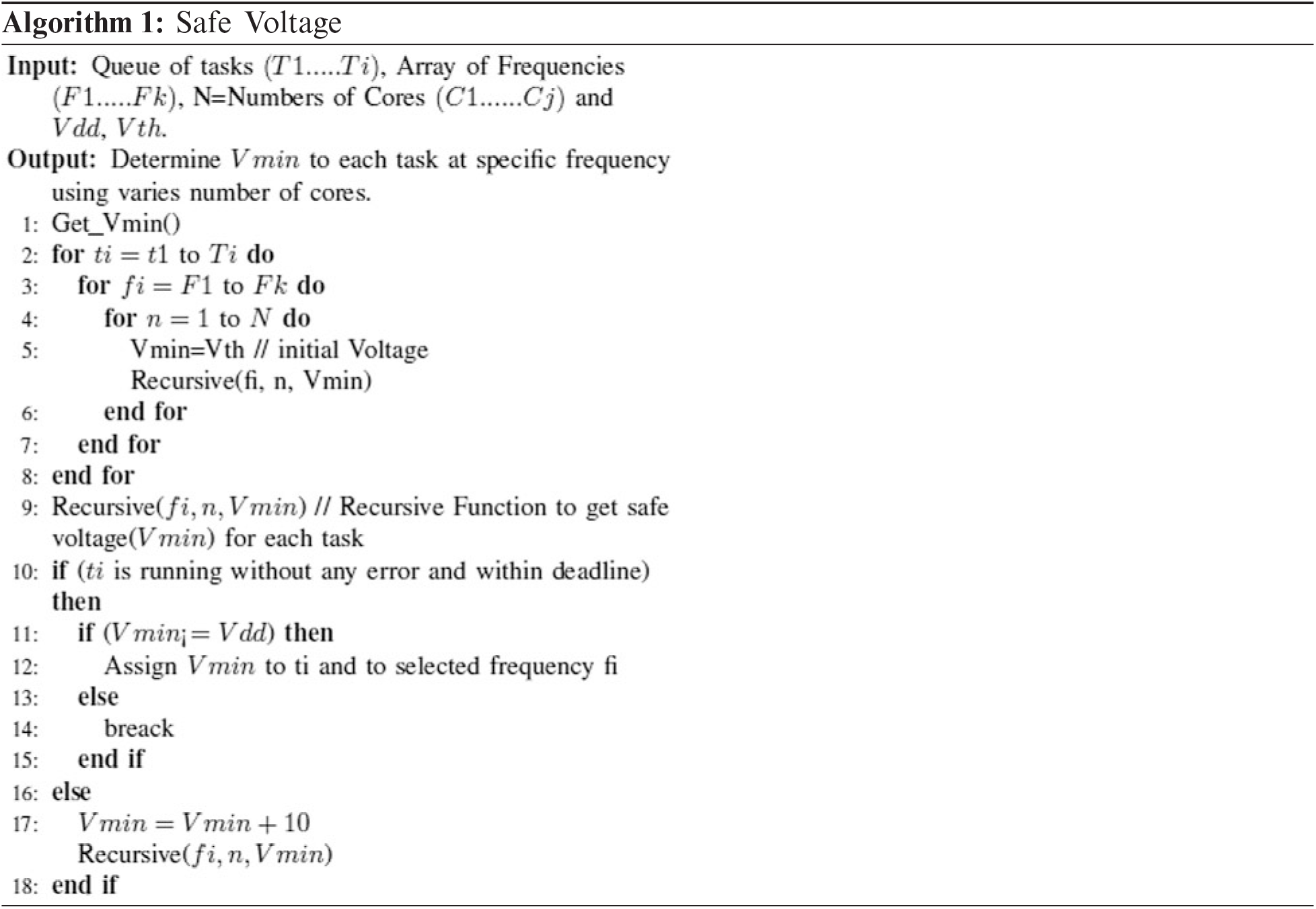
In Algorithm 1, the goal of the Safe Voltage Stage (Section 3–1) that includes a set of measurements is achieved. However, these measurements are taken to determine the state of every core voltage until remains steady even it reaches a safe voltage (Vmin). The increasing voltage is applied to the processor core when the load exceeds its current state. Also, it has the ability to join one or more cores to run one task. The safe voltage value can be calculated based on the following parameters.
-Vth refers to the threshold voltage of a core
-Vdd refers to the system supplied voltage
4.1.1 Voltage Borders identification
To make sure all tasks are implemented properly, the nominal operating voltage is set to a value named safe voltage (Vmin) for all variables. The difference between Vmin and the real operating voltage is a protected guardband with chips and workloads that can work properly. This subsection focuses on a measurable study of Vmin. In Algorithm 1, few cores of the same architecture are applied to compromise the probable guardbands of each workload using the architecture module. Also, it is used to measure the features that determine the Vmin of cores.
4.1.2 Safe Voltage Measurements
In this subsection, a series of experiments are carried out to obtain the safe voltage (Vmin) values. It is considered that the initial voltage level for all experiments is set to Vmin. It should be noted that the value of Vmin is considered as the nominal working voltage. Also, the behavior for each task operating at or above the safe voltage (Vmin) point is taken into account. In these experiments, each task was run 50 trials per configuration setting (frequency level, number of cores) within all levels of the voltage. We were starting from the safe voltage (Vmin) until achieving the optimal value. As in algorithm 1, the safe voltage (Vmin) of each task can be evaluated as follows. Initially, set Vmin = Vth for all cores. Then, Algorithm 1 checks if the task is completed execution without any error and ensuring that Vmin does not exceed the value of Vdd, otherwise the value of the voltage is incremented by 10 V. Nevertheless, Algorithm 1 checks again the safe voltage (Vmin) to all tasks. After that Algorithm 1 repeats the above directives in addition to varying the core’s frequency and the number of the cores. Several tasks are performed offline to find the lowest Vmin value that allows a CPU to get correct operation and work properly with any workload [7]. Algorithm 1-time complexity equal to O ((2N)2), where N is the number of tasks.
4.2 Optimal Energy and Utilization Levels
In Algorithm 2, a set of m cores [C1, C2 … Cm] is considered, each core can run by two frequencies independently. Also, two frequency levels are defined as fh (high frequency) and fl (low frequency). It is considered that fh is the highest frequency per core as a starting point. This paper used Earliest Deadline First (EDF) scheduler. The EDF is an optimal dynamic priority scheduling algorithm used in multicore systems. In EDF, if the CPU usage is less than 100%, then it means that all the tasks have met the deadline. The core Cj is executing n tasks Ti = (Ti1 …Tin). Each task Tij has many features depending on its criticality which are Tij = (cij; dij; tij) where tij is its period, dij is the deadline and it is supposed to be equal tij and finally, cij is the worst-case execution time which depends on the running core frequency. Thus, the computation time of each task is denoted as an array [Cflij; Cfhij ] in which Cfl − ij is the worst-case execution time (wcet) that is estimated at frequency fl. Furthermore, Algorithm 2 supports the complete execution of each task before reaching its worst-case time. Thus, the worst-case time (wcet) is considered as the critical time value to complete doing all that task analysis.
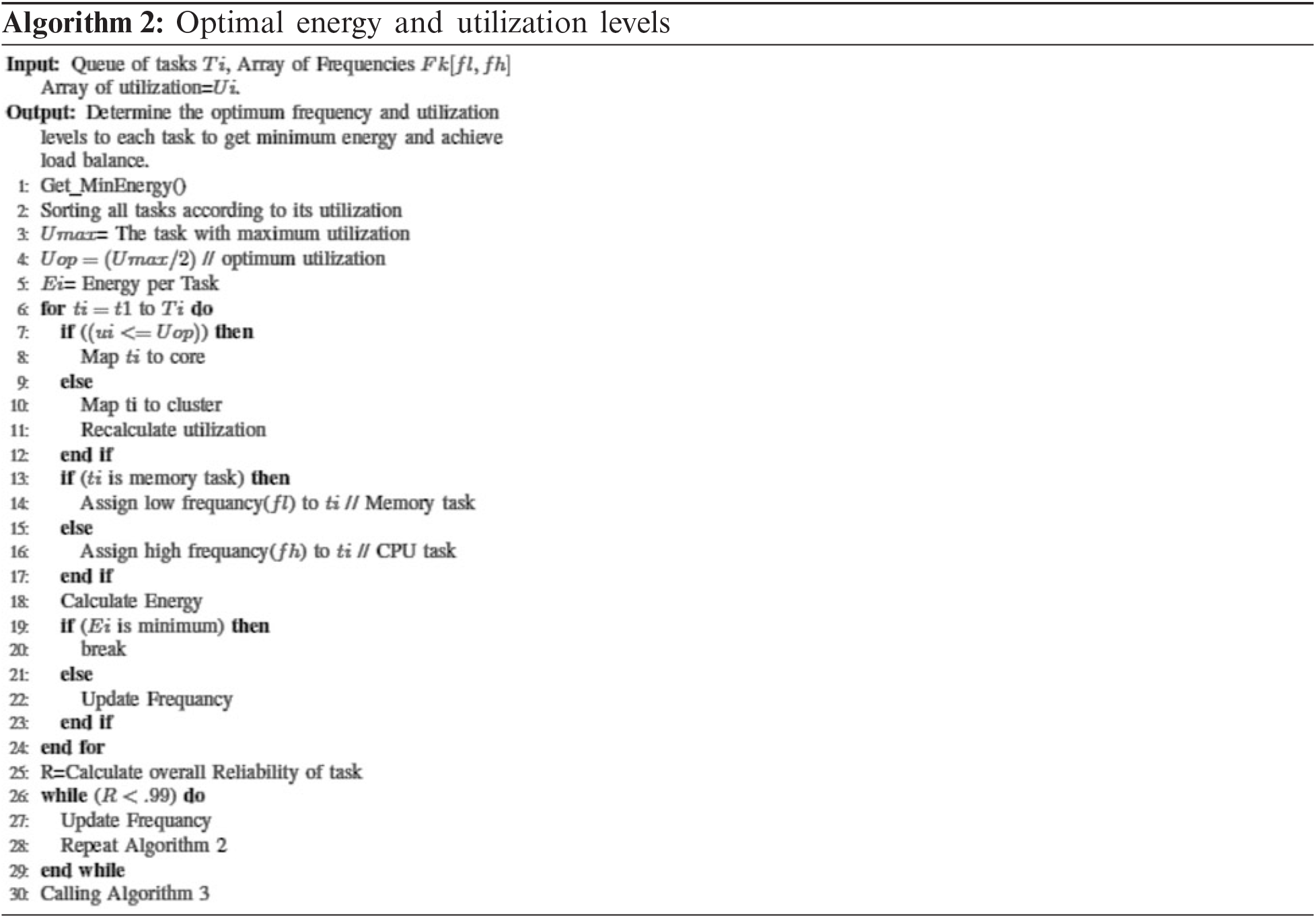
The utilization of a task Tij running at frequency fi is Ufiij = Cflij/Ti. Henceforth we will assume that all tasks are assumed to run on a level of frequency that is assigned to the same core. The reason behind that decision is to avoid overheads (time delay for frequency switching). Thus, the tasks that are running on the same frequency level will be allocated to the same core or a set of cores according to their total utilization. The total core utilization (UCi) is defined as the sum of all utilizations of tasks assigned to that core Cj. Also, there are a queue of tasks and a queue of their utilizations. Initially, tasks are ordered in the task queue according to their deadlines and utilizations. Then the task with maximum utilization (Umax) is found at the tasks queue that is named while optimum utilization is named as (Uop) where Uop = Umax/2, [as in lines 2 to 5] in Algorithm 2. After that, the algorithm checks each task, if its utilization is less than Uop. This is leading to mapping all these tasks to the appropriate core. Otherwise, these tasks are mapped to the cluster and recalculate their utilization [as in lines 7 to 12]. After completing the above steps, each task will run at any core or cluster. Then, frequency assignments are carried out according to the task type. Whereas CPU task is assigned to high frequency, and Memory task is assigned to low frequency [as in lines 13 to 17]. After that, the energy is computed for each task in addition to checking if minimum energy is obtained. If the minimum energy or reliability (R) is less than 0.99 [as in lines 18 to 30] the frequencies will be updated and the processor is repeated. Finally, the reliability per task (R) is calculated to make sure that the system has high reliability [as in lines 25 to 29]. Algorithm 2-time complexity equal to O (N), where N is the number of tasks.
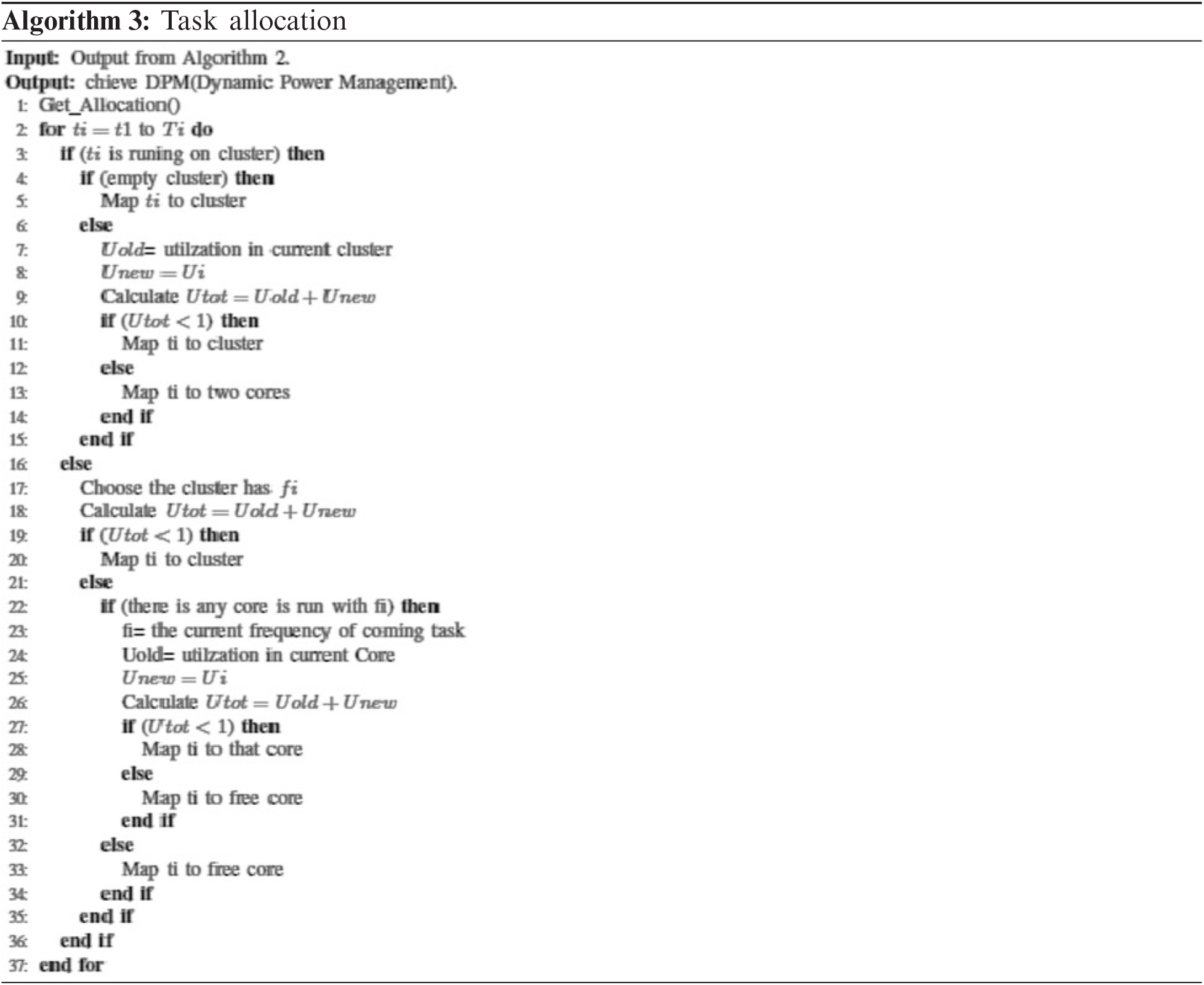
Once the energy-efficient selector method has been applied as in Algorithm 2 that determines each task’s frequency level and this task will run on an individual core or cluster as well. In this subsection, it is desirable to achieve the goal of the third stage for the proposed module architecture. As a result of Algorithm 2, the tasks may have the same frequency level or have different levels of frequency. Algorithm 3 can save energy by using DPM (Dynamic Power Management). The process of Algorithm 3, is started by choosing separate tasks that have the same frequency level. These tasks could be assigned to a cluster, two cores, or one core. The first scenario of Algorithm 3, which chooses the tasks that should run on a cluster. After that Algorithm 3 checks if there are empty clusters or not. In case of no empty cluster is found, the process will check the total utilization of this busy cluster (Utot) after adding those additional tasks or part of them. If Utot is less than one then it can map some or all tasks to that cluster with condition Utot < 1. If this condition is not be obtained then map those tasks for two cores [as in lines 3 to 15]. In the second scenario of Algorithm 3, the current task (ti) will run on the individual core. So, the process searches for a cluster having the same frequency of ti. After that, the total utilization of this cluster (Utot) will be computed after adding that additional ti. If Utot is less than one, then it can map ti to that cluster [as in lines 16 to 20]. In the third scenario of Algorithm 3, the process searches a core with fi where fi the frequency of the current task ti. If Algorithm 3 found a core with fi, it checks the (Utot) after adding that additional ti. If Utot is less than one then it can map ti to that core. Otherwise, Algorithm 3 maps it to an underutilized core [as in lines 21 to 35]. Algorithm 3-time complexity equal to O (N), where N is the number of tasks.
This section presents the experimental results for different applications on various platforms. Also, it provides an analysis of the obtained results. In this paper, the Gem5 simulator [18] is used to develop the proposed hybrid model. Gem5 simulator is one of the most suitable design tools for computer architecture researchers. This simulation infrastructure enables researchers to model modern computer hardware on a cycle level with the aid of boot undamaged Linux operating systems and implement comprehensive applications for a wide range of architectures including X86, Arm, and RISC-V.
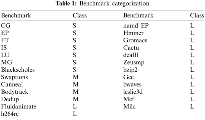
To validate the proposed model, twenty-five benchmarks are applied from three various benchmark suites: the NAS Parallel Benchmark Suite v3.3.1 (NPB) [19,20], the SPEC CPU2006, and the PARSEC v3.0 [21,22]. NPB is software designed to measure the efficiency of parallel mainframes and has been used in many performance and energy efficiency studies [23,24]. This analysis is focused mainly on multicore implementation. We used 6 NPB parallel benchmarks for multithread executions and moreover 13 SPEC CPU2006 one thread benchmarks (both FP and INT class) (each with a different portion of variety in voltage components, CG, EP, FT, IS, LU, MG). Also, we used 6 PARSEC multithread parallel benchmarks (swaptions, blackscholes, fluidanimate, canneal, bodytrack). In the experimental evaluation, the workloads benchmarks are characterized in benchmark throughput terms as the number of instructions per second (IPS) added to the number of memory access, where IPS values spread over the range. Application workloads are categorized based on their IPS values and memory access as a small, medium, and large class. They are denoted by S, M, and L respectively as depicted in Tab. 1. For example, the task with a large number of IPS added to memory access is classified as large (L class).
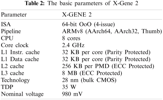
The proposed model is performed on the state-of-the-art ARMv8 micro-servers: Applied Micro’s (now Ampere Computing) X-Gene 2. ARMv8. X-Gene2 consists of three independent voltage domains, the PMD, SoC, and DRAM domains. It provides knobs for under-volting each of the three domains independently. A PMD domain contains cores, L1 instruction, data caches, and L2 cache. SoC domain contains the L3 cache, DRAM controllers, the central switch, and the I/O bridge. Finally, the DRAM domain contains all the DIMMs. In this paper, under-volting of the PMD domain that contains the eight cores of the CPU is only considered. The key properties of processors X-Gene 2 are presented in Tab. 2 which run at Linux kernel.
The applications are classified into memory tasks that can be allocated to run on single cores, while CPU tasks can be run on multiple cores as separate threads, which means adaptive multi-core architectures. This enables the X-Gene 2 to construct many prototypes on the commercially used Architecture Set of Instructions (ISA). In this context, the effectiveness of such architectures will be tested and evaluated to ensure reliability-aware scheduling and energy efficiency in multicore systems. As a first step, it’s necessary to measure a multicore system’s efficiency and accuracy. To apply this the tasks are running at the high frequency of each core (X-Gene 2 at 2.4 GHz), and for the second time, at the half frequency (1.2 GHz). According to our conducted experiments, it is important to recognize that clock frequencies are greater than half of the clock that has Vmin protection similar to the higher clock frequency. Also, frequencies are smaller than the half clock having similar safe voltage (Vmin) as in the half clock. For the purpose of clarification, both cores of the clusters are able to support either clock skipping and clock division to respectively set the effective frequency of the cluster relative to its clock source. Naturally, a clock ratio of 1/2 is applied to the clock input. Therefore, it is not introduced any results for the intermediate frequencies since they provide the same Vmin points. Exceptionally, there are much higher energy savings than 1.2 GHz, with minimal performance impacts. The explanation is that the new CPPC (Collaborative Processor Performance Control) power and performance management requirements of ACPI 5.1 are enforced by these micro-servers [25]. CPPC is a modern way that can monitor core’s performance using an objective continuous frequency scale rather than a discrete Pstate scale (as in legacy ACPI). In reality, the current frequency of the microprocessor is thus scaled below and above 1.2 GHz when requested for 1.2 GHz during runtime. So it offers an average of 1.2 GHz effectively. The actual frequency properties are thus constrained by the highest frequency setting, which is more than half in that case (without clock division). This is an interconnecting frequency strategy given by the CPPC and is not subject to software modification. As in X-Gene 2, it is not possible to observe the same behavior below 1.2 GHz. So, it is reported X-Gene 2 experiments with two different frequencies, 2.4 and 1.2 GHz, are based on an interesting characterization found. The selected two Vmin/F levels, FL = [fl, fh], are associated with the states defined that are based on the core’s energy/time or utilization: (Vmin, 1.2 GHz) and (Vmin, 2.4 GHz). These Vmin/F levels, which are equally separated, are within a nominal Vmin/F levels range. Also, the levels are used by simulators, whose power and performance values have a linear relationship. In this paper, when a higher frequency than 2.4 GHz is used. It provides only marginal improvements in execution times. On the other hand, a lower voltage than 1.2 GHz is not considered as it negatively increases the leakage power consumption. In this experiment, fixed Vmin/F level switching time/energy overheads to be in the order of 0.5 micro-second/1 microjoules, respectively [26]. These time/energy overheads are very small and often negligible. Also, these overheads are taken into account during the proposed hybrid model evaluations.
In this section, the results of comparing the proposed hybrid model are assessed using different metrics and compared with other competing methods such as Voltage/Frequency Scaling [25], VDP pseudocode [13], Greedy pseudocode [13], Feedback Controller pseudocode [13] Ondemand governor pseudocode [13], Worst Fit Decreasing Utilization (WFDU) [23] and heterogeneous fairness-aware energy-efficient framework (HFEE) using different metrics is presented.
5.4.1 Safe Voltage Characterization
Fig. 3 shows the safe voltage (Vmin) results on X-Gene 2 for twenty-five benchmarks. The value of Vmin for each task is considered the lowest voltage setting obtained after completing ten runs of a task without any notification for a hardware error, such as a process timeout or system crash. The experiments are conducted on a different number of cores at frequencies 2.4 and 1.2 GHz. As shown, the safe voltage for all benchmarks has close and nearby values for the same number of cores and frequency. In this context, the safe voltage is slightly affected by the type of workload, on the other hand, it is affected by the operating frequency and number of cores. On the basis of this analysis, we conclude that the dominant factors that can affect the value of Vmin and the possibility of failure are the frequency and the number of cores. For the same number of cores at different frequencies, the workload has minimal influence on Vmin in multicore executions. However, we could found that low frequencies provide low safe voltage Vmin values for most benchmarks. It should be noted that operating voltage can decrease by 4% of Vmin by reducing the frequency half of its value as the clock division is triggered at this frequency. Moreover, the voltage can further be reduced by 5% at a certain frequency level when using different a number of cores. Fig. 4 shows the safe voltage (Vmin for different workloads. As shown in Fig. 4a, individual cores can achieve constant values for low-frequency levels, while clusters give high variability of Vmin. However, the situation is reversed for high-frequency levels as depicted in Fig. 4b.
5.4.2 Consideration of Shared Energy and Efficiency
Energy consumption is a valuable metric that is directly translated into a cost. However, it may also include very slow (i.e., lower frequency) device configurations that can affect the latency and throughput specifications. To avoid such bias in comparison purposes, the energy-delay product (EDP = E * D) and the energy-delay squared product (EDDP = E * DD) are considered. Given that the proposed model is focusing on server-grade CPUs. Therefore, for fair comparisons, the normalized energy-delay squared product (EDDP) is used for all experiments. In addition, it is preferable to present the relation between the energy and performance measures. Furthermore, the analysis shows that different workloads could be classified as (CPU, Memory access). Figs. 5 and 6 show the energy consumption when applying various methods. Clearly, the proposed model achieves lower values of energy consumption that give lower normalized EDDP. This is noticeable specifically when having mixed workloads such as CPU and memory tasks, and small, medium, and large loads. These workloads examine the robustness and reliability of the proposed hybrid model compared with other competitor methods. In the case of workloads W1, W7, and W14, the energy-saving results pointed out that there is a 20% to 55% gap in values between the proposed model and the other methods. In addition, there is an average improvement of up to 15% in other workloads such as W2, W6, W11, and W13. While there are remarkable improvements in the remaining workload.

Figure 3: Experimental results on different tasks using various number of cores. (a) Safe voltage (Vmin) at 1.2 GHz (b) safe voltage (Vmin) at 2.4 GHz
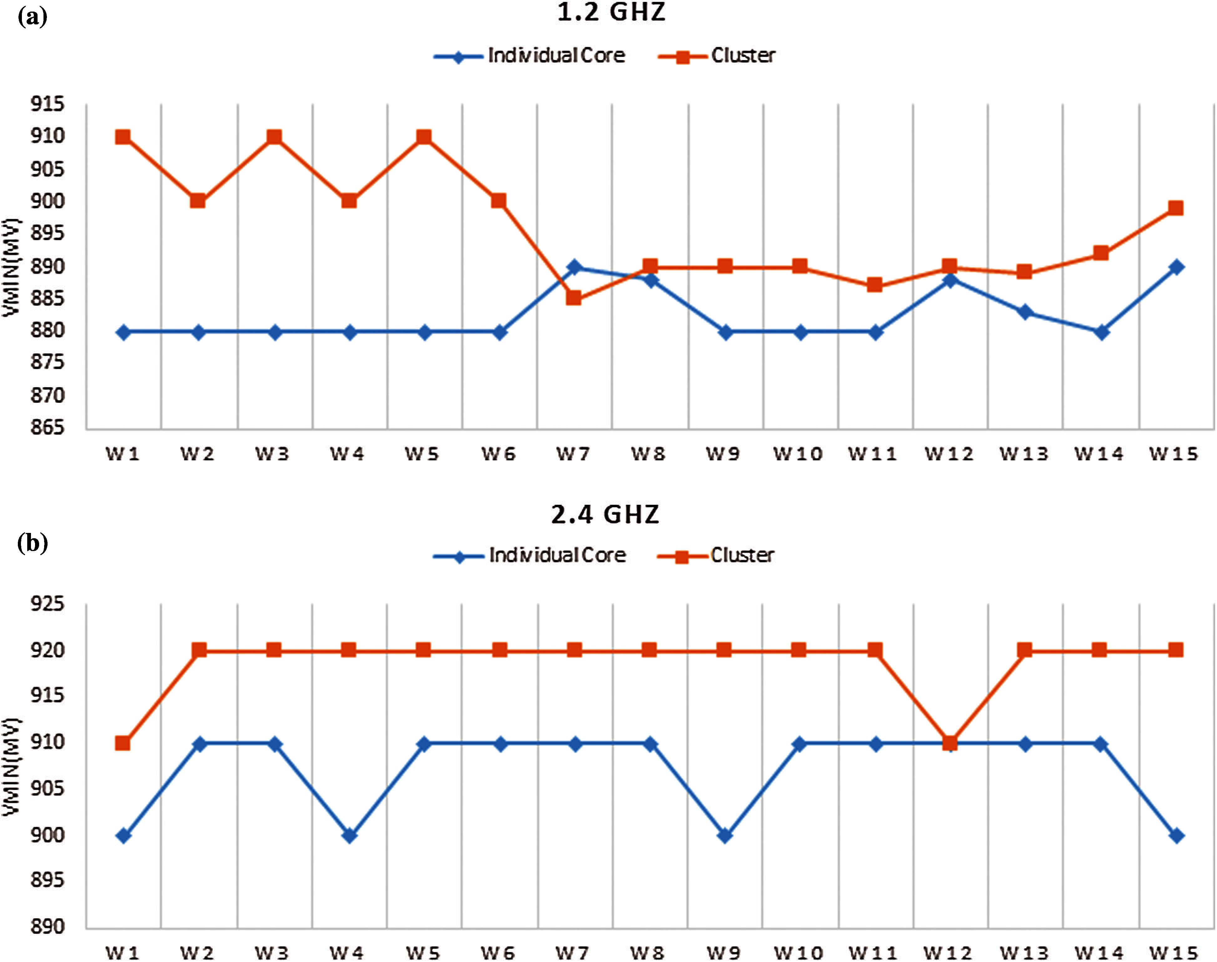
Figure 4: Experimental results on different workloads
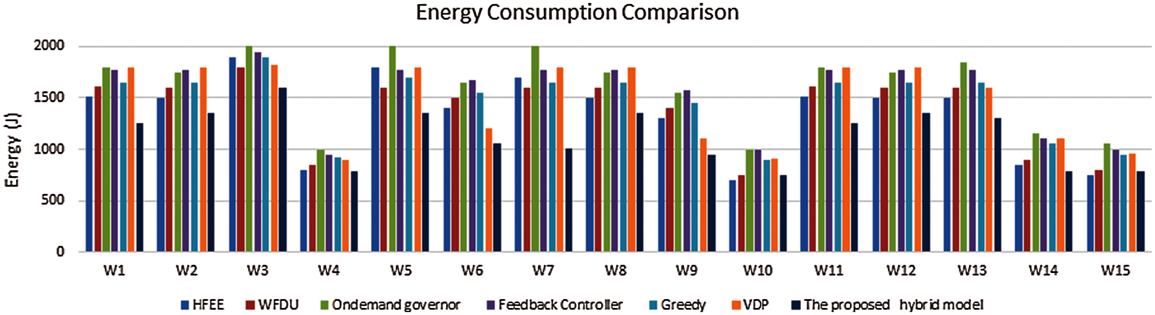
Figure 5: Energy consumption
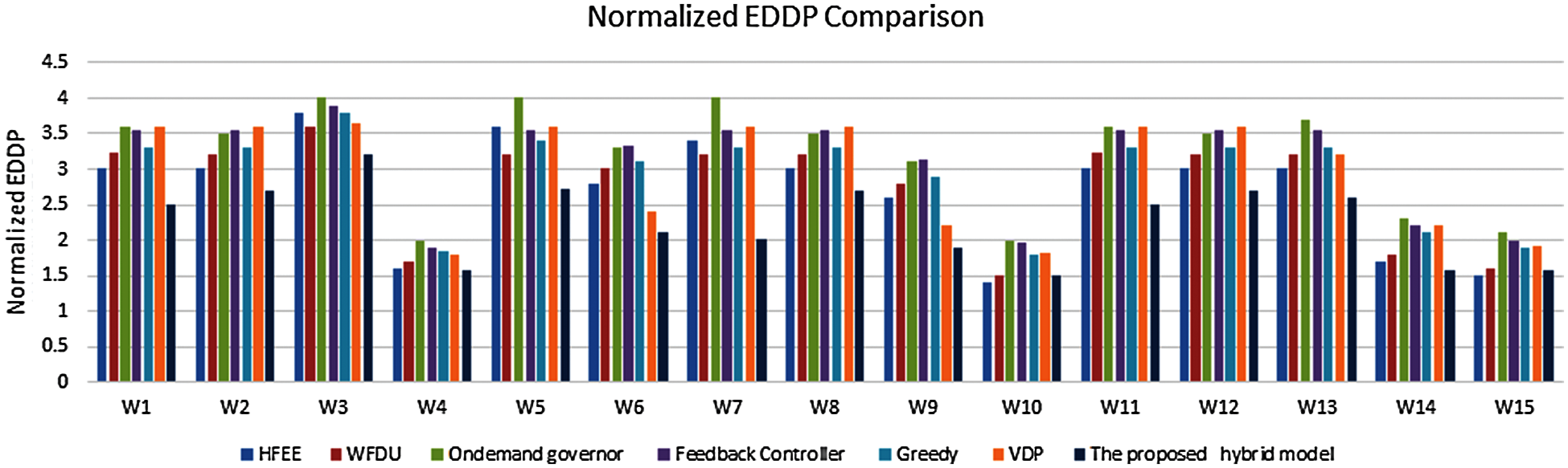
Figure 6: Normalized EDDP
Fig. 7, shows the makespan results as another performance metric to evaluate the proposed model. It should be noted that lower values of makespan and energy consumption of the proposed hybrid model give lower normalized EDDP compared with other approaches. These results indicate that the proposed hybrid model achieved lower energy consumption. Additionally, the proposed model decreases the makespan by minimizing the task’s execution time. For instance, running a task at a high frequency can decrease the task execution time. So, workloads such as W4, W8, W10, and W15 give outstanding makespan results. However, some makespans for few workloads are not improved.
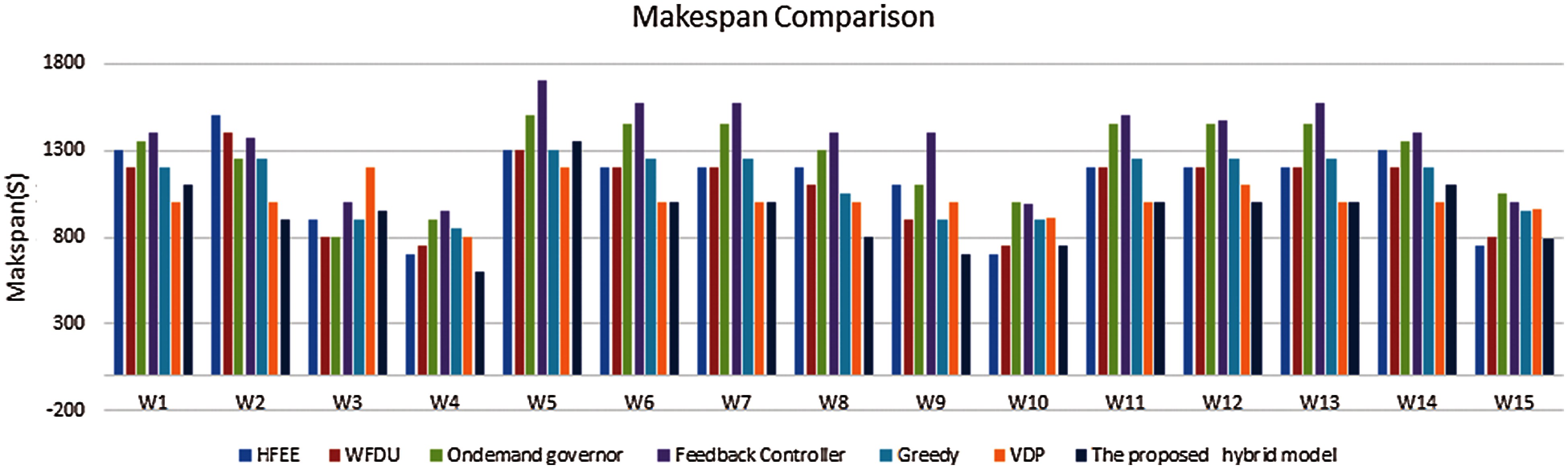
Figure 7: Makespan comparisons
As explained, utilization is considered as the main factor for the assessment of the proposed hybrid model. Fig. 8 shows comparisons between the proposed model and other approaches. As depicted, both the proposed model and WFDU give comparable results. This is because both approaches consider the utilization aspect. But in most cases and various workloads such as W1, W7, and W11, the proposed hybrid model achieved the best utilization. Also, it is worth noting that the VDP approach does not perform well as it does not consider the utilization aspect.
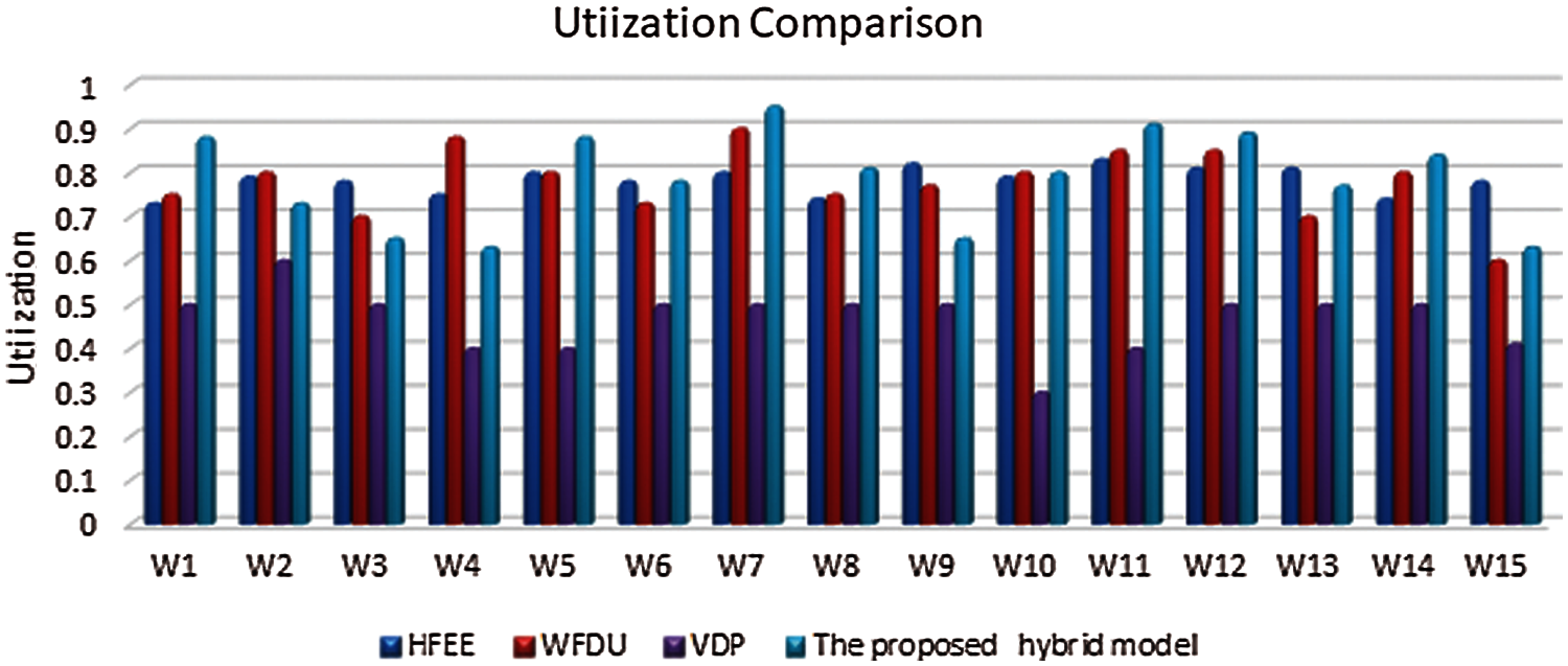
Figure 8: Utilization comparisons
Results show that the proposed hybrid model outperforms in all performance measures compared with other competitors. Besides, the proposed model is suitable for determining the best frequency levels for processing various types of workloads on different platforms. Moreover, the proposed model optimizes the number of required cores and allows the scheduling process to be more deterministic. This indicates the robustness and reliability of the proposed model, thus making the scheduling process more deterministic; therefore, the execution times present a lower standard deviation. The proposed model has given the higher utilization but not the lower standard deviation compared with others.
In this paper, a hybrid model for reliability-aware scheduling and energy efficiency in multicore systems has been proposed. The proposed model augments the greedy approach with dynamic programming to enhance the utilization per core. In addition, the introduced model is locally optimizing the individual voltage and frequency level per-core by minimizing the core energy consumption and globally find the proper task allocation that gives minimum makespan execution times. As demonstrated, the proposed model achieved the best utilization while preserving the load balance compared with other heuristics models. Experimental results showed that the proposed model can achieve 50% and 20% energy saving for heavy and light workloads respectively. Furthermore, the makespan for all workloads is reduced by 18% compared to the other competitors. This work can be expanded to implementations on large-scale systems, and considering online operating system control and heterogeneous cores. This will enable the introduced models to run on bigger systems, and be able to withstand huge workloads to give a bigger boost in energy efficiency.
Acknowledgement: The authors would like to acknowledge the group effort made in this study. The authors express appreciation to Dr. Aya Sedky Adly for sharing her experience, providing advice and encouragement.
Funding Statement: The authors received no specific funding for this study.
Conflicts of Interest: The authors declare that they have no conflicts of interest to report regarding the present study.
1. H. A. Hassan, S. A. Salem and E.-S. M. Saad, “Energy aware scheduling for real-time multi-core systems,” International Journal of Computer Science Engineering, vol. 7, no. 4, pp. 167–175, 2018. [Google Scholar]
2. M. Bambagini, M. Marinoni, H. Aydin and G. Buttazzo, “Energy-aware scheduling for real-time systems: A survey,” ACM Transactions on Embedded Computing Systems, vol. 15, no. 1, pp. 1–34, 2016. [Google Scholar]
3. G. Desirena-López, A. Ramírez-Treviño, J. L. Briz, C. R. Vázquez and D. Gomez-Guti, “Thermal-aware real-time scheduling using timed continuous petri nets,” ACM Transactions on Embedded Computing Systems, vol. 18, no. 4, pp. 1–24, 2019. [Google Scholar]
4. Y. Qin, G. Zeng, R. Kurachi, Y. Li, Y. Matsubara et al., “Energyefficient intra-task DVFS scheduling using linear programming formulation,” IEEE Access, vol. 7, pp. 30536–30547, 2019. [Google Scholar]
5. S. Hajiaminia and B. A. Shirazib, “A study of DVFS methodologies for multicore systems with islanding feature,” Advances in Computers, vol. 119, no. 9, pp. 35, 2020. [Google Scholar]
6. J. Boudjadar, “A study of the trade-off energy consumption-performance schedulability for DVFS multicore systems,” International Journal of Computer and Information Engineering, vol. 14, no. 11, pp. 380–391, 2020. [Google Scholar]
7. G. Papadimitriou, M. Kaliorakis, A. Chatzidimitriou and D. Gizopoulos, “Harnessing voltage margins for energy efficiency in multicore cpus,” in Proc. of the 50th Annual IEEE/ACM Int. Symp. on Microarchitecture, Cambridge, MA, pp. 503–516, 2017. [Google Scholar]
8. S. Yoo, Y. Jo, K. W. Cho and H. Bahn, “Real-time power-saving scheduling based on genetic algorithms in multi-core hybrid memory environments,” The Journal of the Institute of Internet, Broadcasting and Communication, vol. 20, no. 1, pp. 135–140, 2020. [Google Scholar]
9. L. Premi, “Gator. A game theory approach to resource allocation for heterogeneous cpus,” Politecnico di Milano Scuola di Ingegneria Industriale e Dell’informazione Tesi di Laurea Magistrale in Computer Science and Engineering, 2020. [Google Scholar]
10. N. Chawla, A. Singh, H. Kumar, M. Kar and S. Mukhopadhyay, “Securing iot devices using dynamic power management: Machine learning approach,” IEEE Internet of Things Journal, pp. 1, 2020. https://doi.org/10.1109/JIOT.2020.3021594. [Google Scholar]
11. H. A. Hassan, S. A. Salem and E. M. Saad, “A smart energy and reliability aware scheduling algorithm for workflow execution in DVFS-enabled cloud environment,” Future Generation Computer Systems, vol. 112, pp. 431–448, 2020. [Google Scholar]
12. B. Salami, H. Noori and M. Naghibzadeh, “Fairness-aware energy efficient scheduling on heterogeneous multi-core processors,” IEEE Transactions on Computers, vol. 70, no. 1, pp. 72–82, 2020. [Google Scholar]
13. S. Hajiamini, B. Shirazi, A. Crandall and H. Ghasemzadeh, “A dynamic programming framework for DVFS-based energy-efficiency in multicore systems,” IEEE Transactions on Sustainable Computing, vol. 5, no. 1, pp. 1–12, 2019. [Google Scholar]
14. S. Yari-Karin, A. Sahraee, J. Saber-Latibari, M. Ansari, N. Rohbani et al., “A comparative study of joint power and reliability management techniques in multicore embedded systems,” in 2020 CSI/CPSSI Int. Symp. on Real-Time and Embedded Systems and Technologies, Tehran, Iran, IEEE, pp. 1–8, 2020. [Google Scholar]
15. A. Roy, H. Aydin and D. Zhu, “Energy-aware standby-sparing on heterogeneous multicore systems,” in 2017 54th ACM/EDAC/IEEE Design Automation Conf., Austin, TX, USA, IEEE, pp. 1–6, 2017. [Google Scholar]
16. E. Dubrova, Fault-Tolerant Design. Berlin, Germany: Springer, 2013. [Google Scholar]
17. M. A. Haque, H. Aydin and D. Zhu, “On reliability management of energy-aware real-time systems through task replication,” IEEE Transactions on Parallel and Distributed Systems, vol. 28, no. 3, pp. 813–825, 2016. [Google Scholar]
18. A. N. Semakin, “Simulation of a multi-core computer system in the gem5 simulator,” in AIP Conf. Proc., AIP Publishing LLC, vol. 2318, 2021. [Google Scholar]
19. C. Bienia, S. Kumar, J. P. Singh and K. Li, “The parsec benchmark suite: Characterization and Architectural Implications,” in Proc. of the 17th Int. Conf. on Parallel Architectures and Compilation Techniques, Atlanta, GA, USA, pp. 72–81, 2008. [Google Scholar]
20. M. Aftosmis, W. Chan, G. Guruswamy, P. Kolano, S. Murman et al. NAS parallel benchmarks suite, v3.3.1, [Online]. Available: https://www.nas.nasa.gov/publications/npb.html. [Google Scholar]
21. J. L. Henning, “Spec cpu2006 benchmark descriptions,” ACM SIGARCH Computer Architecture News, vol. 34, no. 4, pp. 1–17, 2006. [Google Scholar]
22. B. Lepers, V. Quéma and A. Fedorova, “Thread and memory placement on fNUMAg systems: Asymmetry matters,” in 2015 {USENIX} Annual Technical Conf. ({USENIX}{ATC} 15Santa Clara, CA, pp. 277–289, 2015. [Google Scholar]
23. A. Guasque, P. Balbastre, A. Crespo and S. Peiró, “Energy efficient partition allocation in mixed-criticality systems,” PLOS ONE, vol. 14, no. 3, pp. e0213333, 2019. [Google Scholar]
24. M. Curtis-Maury, “Improving the efficiency of parallel applications on multithreaded and multicore systems,” Ph.D. dissertation. Virginia Tech, 2008. [Google Scholar]
25. G. Papadimitriou, A. Chatzidimitriou and D. Gizopoulos, “Adaptive voltage/frequency scaling and core allocation for balanced energy and performance on multicore cpus,” in 2019 IEEE Int. Symp. on High Performance Computer Architecture, IEEE, pp. 133–146, 2019. [Google Scholar]
26. J. Murray, T. Lu, P. Wettin, P. P. Pande and B. Shirazi, “Dual-level dvfs enabled millimeter-wave wireless noc architectures,” ACM Journal on Emerging Technologies in Computing Systems, vol. 10, no. 4, pp. 1–27, 2014. [Google Scholar]
 | This work is licensed under a Creative Commons Attribution 4.0 International License, which permits unrestricted use, distribution, and reproduction in any medium, provided the original work is properly cited. |