DOI:10.32604/cmc.2022.020884
| Computers, Materials & Continua DOI:10.32604/cmc.2022.020884 | |
| Article |
Aeroelastic Optimization of the High Aspect Ratio Wing with Aileron
1Department of Aerospace Engineering, Sharif University of Technology, Tehran, 11155-8639, Iran
2College of Engineering and Technology, American University of the Middle East, Kuwait
3Faculty of Aerospace Engineering Engineering, IHU, Tehran, Iran
4Department of Mathematics, Cankaya University, Etimesgut, Ankara, Turkey
5Department of Medical Research, China Medical University Hospital, China Medical University, Taichung, Taiwan
*Corresponding Author: Fahd Jarad. Email: fahd@cankaya.edu.tr
Received: 12 June 2021; Accepted: 12 August 2021
Abstract: In aircraft wings, aileron mass parameter presents a tremendous effect on the velocity and frequency of the flutter problem. For that purpose, we present the optimization of a composite design wing with an aileron, using machine-learning approach. Mass properties and its distribution have a great influence on the multi-variate optimization procedure, based on speed and frequency of flutter. First, flutter speed was obtained to estimate aileron impact. Additionally mass-equilibrated and other features were investigated. It can deduced that changing the position and mass properties of the aileron are tangible following the speed and frequency of the wing flutter. Based on the proposed optimization method, the best position of the aileron is determined for the composite wing to postpone flutter instability and decrease the existed stress. The represented coupled aero-structural model is emerged from subsonic aerodynamics model, which has been developed using the panel method in multidimensional space. The structural modeling has been conducted by finite element method, using the p-k method. The fluid –structure equations are solved and the results are extracted.
Keywords: Flutter speed; flutter frequency; composite wing; aileron;; multi-disciplinary optimization method
Aeroelastic conditions are the main features to be considered in an the design of Arial vehicle. In other words, due to the structural interaction of the Arial components with the aerodynamics, it potentially yields to a coupling between fluid and structures. Among the aeroelastic phenomena, self-vibrations, at a certain speed, which is called fluttering, are considered as the most common problem in coupled systems. This destructive phenomenon will lead to the aggravation of high-amplitude vibrations effect [1]. In the absence of sufficient damping in the system, this will lead to structural failure [2]. Special interest has been raised for the fluttering effect following the crash down of an airplane in Lancaster, in 1916 [3]. The accident survey of bomber revealed that self-vibration of the airplane was the main cause of such failure. The mechanism involved coupling of the twisting modes of the body and rotating the control surfaces. The latter is commonly known as the asymmetrical mode. The control surfaces are usually operated independently in this type aircraft, and to overcome this problem, surfaces are connected to each other and worked simultaneously [4]. Wing flutter emerged from instability of these adjoining surfaces became apparent during World War I. Following the yielded issues, the application of the aileron as a wing component became widespread. Engineers suggested that balancing weights around the hinges of the control surfaces can be adopted as a mean of preventing flatulence. The adopted strategy can efficiently postpone the flutter effect [5]. Following this procedure, several low-risk flutter examples of control has occurred. Even know this strategy yielded issues regarding the effectiveness and reversal functioning of the control surface, they are not as catastrophic as the aileron [6]. The studies on aileron effectiveness in subsonic regime, as an active control surface, to decrease undesirable loading, was conducted by Jacobs [7]. This approach showed that the aileron has an impact on flutter speed and frequency. These investigations were compared with the numerical aero-elastic analysis, in further studies [6,8].
Several attempts to represent analyzing tools regarding the flutter behavior, in a different regime based on the computational theories, were performed [9]. In the 1920 s and 1930 s, the newly developed unsteady aerodynamic theory as a highlighted aerodynamic achievement was introduced [10]. Thirty years later, strip aerodynamic theory, beam structural model, and non-permanent lifting surface methods, are developed to apply the finite element models in order to approximate the reduced frequency [11]. Following the advent of digital computers, other powerful representation methods along with the new more precise aerodynamic theories [12,13] as well as efficient modeling of wing structures [14–16] were possible to implement. Since then, control theories and structural dynamics [17] have been employed and become more applicable. The approaches have been founded based on the aerodynamic component division into mass, damping, and stiffness matrices which can be added to structural components. The distribution of mass and stiffness of the structure have a direct effect on the speed and frequency of the Aerial vehicle, and consequently, its flutter [18,19]. It can be concluded that the presence of any structural component with a significant mass and stiffness relative to the mass and stiffness of the main structure can affect the speed and frequency of the flutter (e.g., tank, landing gear, and control surfaces such as an aileron).
Design procedures of airplane structures are completely influenced by control surfaces such as aileron and flaps. This influence has direct effect on wing performances and therefore is considered as one of the challenging problems. The aeromechanical design instructions can be revealed from the study on positioning and instability of the ailerons [20] at the trailing edge of different wings which were conducted by researchers via the Finite volume method [21,22]. Dixon and Mei expanded the use of the applicable design methods for composite panels as they are considered common materials in aerospace industry. These authors have followed the Von Karman strain shifting relationship and first-order quasi-steady aerodynamic theory to show large deviations and first-order quasi-steady aerodynamic theory.
The finite element method (FEM) as another useful tool was more likely employed, especially in designing procedures, for flutter boundary analysis, finite oscillation, and thermal problems [23–25]. Shi [26] represented the gust loads FEM form formulation to study the wing instability behavior. Based on the model, the other studies and designing development were conducted to assess flutter clearance of the wing with the control surfaces [27].
Among the optimization methods [28,29], the multidisciplinary design optimization (MDO) approach plays an important role in the design of the aero structural vehicles under static and dynamic criteria [30]. Design and estimation of the high aspect ratio composite wings performances under flutter conditions and weighting reduction using the MDO method is studied in new aero-structural components [31]. In practice, aerospace structures are subjected to different forces in different parts, which cause stress in the structure. In isotropic structures, it is possible to change the thickness based on the stress state by manufacturing methods. In these structures, the thickness change is continuous and thus the structure's continuity is maintained. In composite structures, designers divide the structure into different parts based on these stress gradients [32]. For each part, along with the lay-up modification, they change the location of the control surfaces appropriately. Thus, thickness reduction is completely dependent on the control surface position especially the aileron one.
In the present paper, the effect of the aileron's position, as well as mass inertial moment on the speed and frequency of the flutter, have been revealed for the composite wing. In addition, FEM is employed for modeling composite wing structure along with aerodynamic panel theory in the purpose of seeking components of the wing structure. The aero-elastic model was solved using the P-K method through the Nastran software. The novel optimization procedure is proposed and applied to find the best position of the aileron with the minimum state of the TSAI–WU stress via USAR [33] and JAR25 [34] criteria and flutter avoidance conditions.
For the sake of a better optimization of the design, several factors have been taken into consideration: dimensions and weight of the aircraft; type of maneuvers (permanent or sudden); weather conditions; magnitude of forces applied. In addition, the wing structure must be able to withstand all different conditions and keep the stability and control with a suitable reliability factor to satisfy and provide a safe and secure flight. In brief, the design of the structure of an aircraft, especially its wing with control surface like aileron, should be implemented in such a way that it should bypass the flutter criterion under the minimum possible weight and stress, following the standard air regulations.
Fig. 1 shows the overall dimensions of the wings. The adopted wing structure is an all composite carbon/epoxy wing (Tab. 1) with a high aspect ratio and laying [45, −45, 45, 0, 90]. The total mass of the wing with the aileron is about 247 kg. The mass of ailerons is about 5 kg. The wing structure has 3 spars and 15 ribs. The different features of the design are thoroughly developed in the following sub-sections.
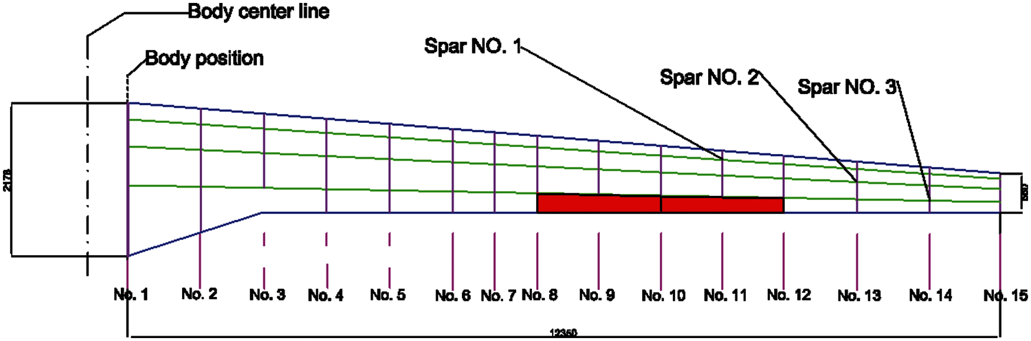
Figure 1: General dimensions of wing and position of aileron reference (the hashed line)
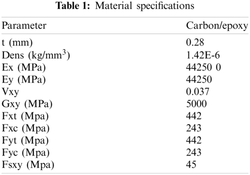
The finite element model of aerodynamics and wing structure is presented in Figs. 2 and 3, respectively.
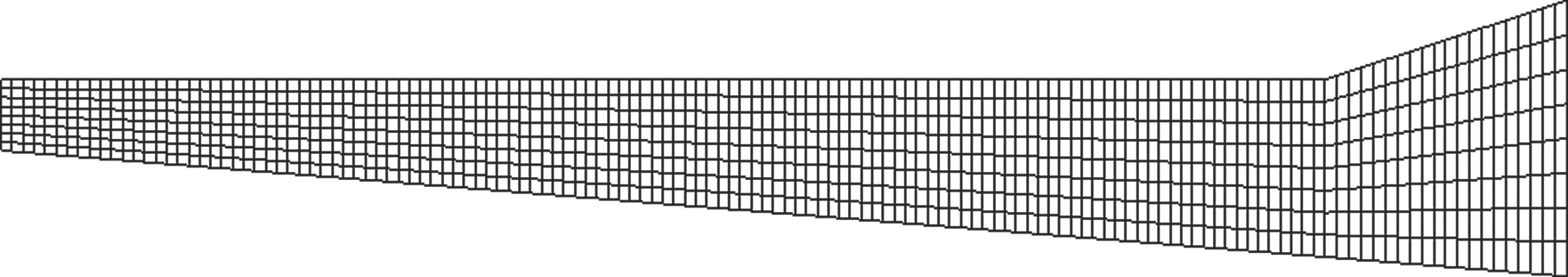
Figure 2: Aerodynamic meshing of wing based on DLM method
Figure 3: Structural mesh of the frame
The boundary conditions for solving this problem, considering that the wing is completely attached to the body, are completely fixed, and are numbered one and two from the beginning of the spar.
In the purpose of a better wing structure implementation, it is necessary that the loads are applied in different maneuver conditions. This stipulation is added in order to cope all different scenarios, encountered in a normal flight and to ensure that the aircraft structure, including its wing and its facility, is able to withstand the worst loading conditions. The aerodynamic loading group determines the worst loading conditions obtained from the above conditions in the worst maneuver conditions, by applying the reliability coefficient in the standards. Different structural members are designed and their strengths are determined in accordance with paragraph JAR25–301 [34] for final loads and loads multiplied by a certain reliability coefficient. In this part, the load limit is defined as the maximum load that may be applied to the structure during the service life. Accordingly, following paragraph USAR-305 (a) [33], the structure must withstand a certain load without permanent deformation; and in accordance with paragraph (USAR-305 (b) the structure must be able to withstand the final load for at least 3 s before rupture. To apply the reliability coefficient, following USAR-305 clause, the reliability coefficient is 15.1 and following USAR307 clause, the critical load coefficient is 3.8. It has been used to apply the load on the composite wing with aileron.
Flutter analysis is conducted by aero elastic section of the Nastran software module. The data required for the flutter analysis is obtained by modal wing analysis. The flow regime for the above- mentioned was selected to cope the worst-case scenario as the unstable regime is considered and the Mach number equal to 0.6 was assigned. The air density was 1.225 kg/m3. For estimating the speed range, 1 to 300 meters per second was considered.
2.3 Effect of Aileron on Flutter
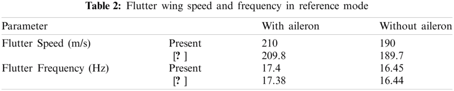
Investigation of the aileron effect on the speed and frequency of the fluttering as the main parameter of design criteria is represented in this section. The results are compared to what extracted by represented model [11] and proposed in Tab. 2. The evaluations show that the flexural mode 3 and the torsional mode 6 of the wings are coupled together and lead to the flutter with error differences below .0.12%. The mode shapes of 3 and 6 of the wings are presented in Figs. 4 and 5, respectively.
For sea-level elevation, the velocity-frequency and velocity-damping diagrams are shown as a sample for the wing, despite aileron in the reference position in Figs. 6 and 7. As shown in the figures, the two frequencies of the system approach each other, as the speed increases, and approach the nearest distance at a speed close to 190 m/s (684 km/h). This indicates that the flutter phenomenon is occurring at this speed. For aero elastic analysis, and according to the matrices of mass, damping and generalized stiffness of aero elastic system, the equations in generalized coordinates are expressed as follows:
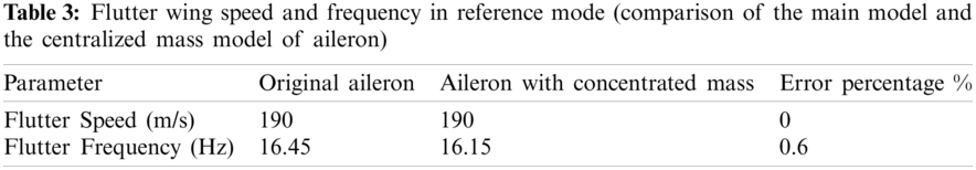
where the M, C, and K are mass, damping, and stiffness matrices, respectively. These matrices are constantly changing and updated with the flow rate. Since the matrices mentioned change with the velocity of the flow, the parameter P in the solution process of the equation also changes constantly. The imaginary part of this parameter is called the frequency and the real part is called damping. Given the assumed solution, it is clear that when the damping is positive (e.g., the true part P becomes greater than zero). The system's response increases over time and tends to infinity. This increasing magnitude causes the structure to diverge. Therefore, the point at which the damping changes from negative to positive is called the flutter point. Following the adopted optimization procedure, the structure can be simplified so that composite wing is considered as shell element. Additionally, the aileron was modeled as a concentrated mass with the main structure of aileron and is located in the center of aileron. The calculation corresponding to flutter parameters for both models are conducted and the results were compared (Tab. 3). The presented results in Tab. 3 highlights the accuracy of the adopted modelling approach. Even though the results of the simplified model are slightly different from the original model, the first model is considered to be valid.
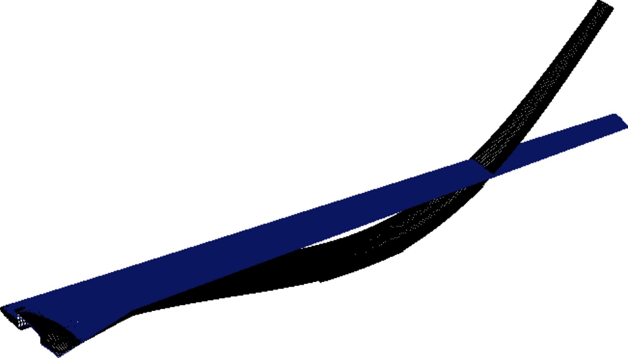
Figure 4: Shape of the third wing mode with aileron (bending = −1/11 Hz)
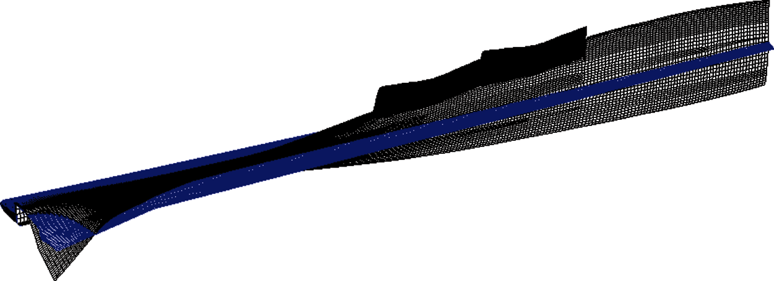
Figure 5: The shape of the sixth wing mode with aileron (torsion = −1/33 Hz)
Figure 6: Damping vs. speed
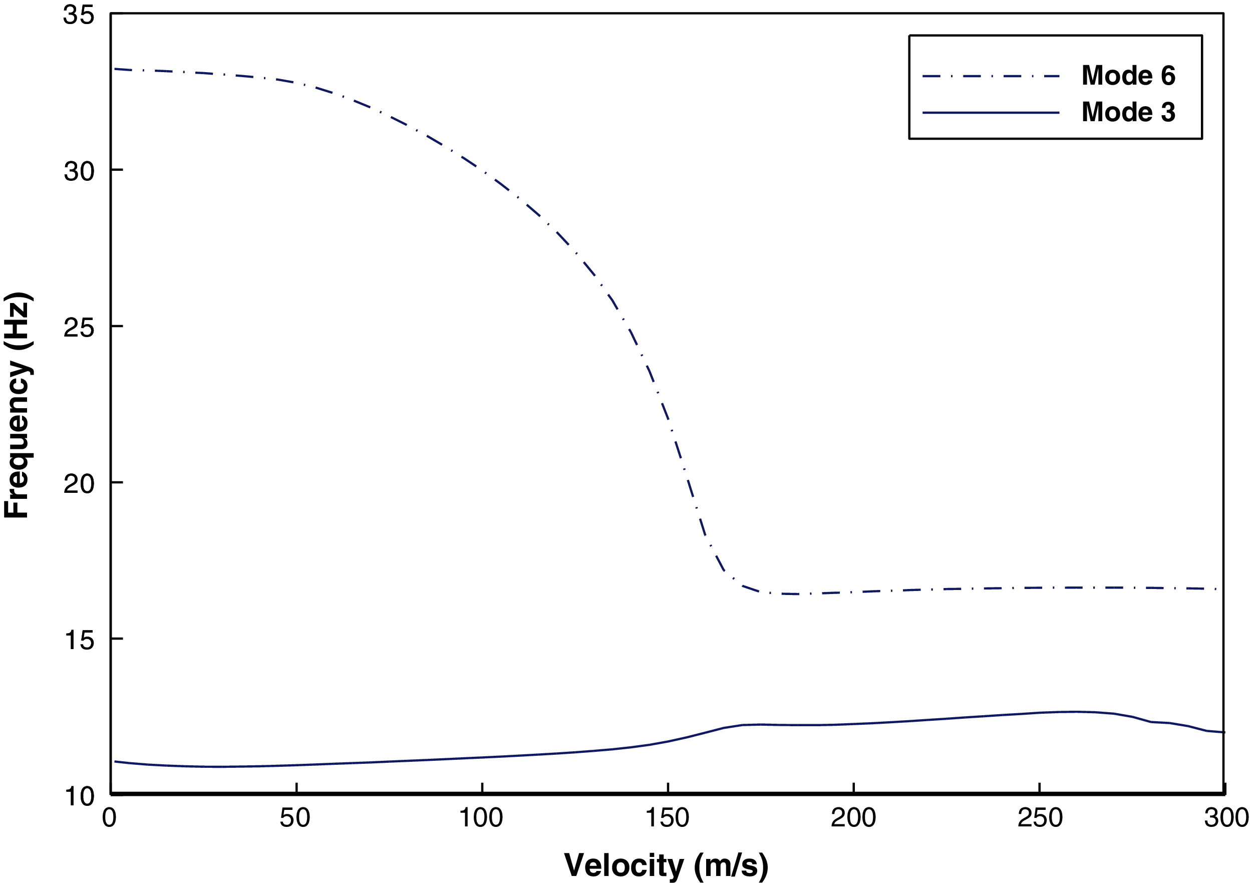
Figure 7: Frequency versus speed
3 Optimization Based on the Strength and Flutter Criteria
According to the Genetic Algorithm (GA) and Artificial Neural Network (ANN), a novel MDO method is adopted to propose the best position of the aileron on the composite wing, in order to postpone flutter and alleviated the stress of the root. The design flow includes parameterization aileron position, optimization algorithm, and a surrogate model on FEM (NASTRAN) software. Design of experiments (DOE) is also employed to create a database composed of the main mentioned composite wing with aileron along with Neural Network Algorithm. Following the created database, the flutter response and TSAI–WU stress criteria of the composite wing are evaluated. The new aileron positions are extracted using numerical calculation. The database is composed of the ANN results that are converged to numerical results. Finally, using the results of the NASTRAN software, the objective function is examined to assess the target goal satisfaction.
The minimum stress due to the above worst-case loadings along with flutter avoidance criteria makes the design optimization algorithm straightforward. Indeed, the procedure is followed to minimize the stress via gust loading along with increasing the flutter speed. The adopted equation is represented below:
where the design variable or weighting coefficient can be introduced as
Based on the meta-models idea besides ANN and also through the FEM aero-mechanical calculations of the original composite wing, DOE method is considered here. The network is trained via a feed forward-back propagation network with 8 hidden layers and one output neuron. Based on the experience, the proper range of the aileron position is set to be in a 5% deviation of the original position. ANN is adopted along with the approximated function (Eq. (2)). The design flow is run by predefined GA, the OF value is approximated and compared with the result of the 3D FEM simulation [23–33] and then ANN database is updated accordingly (Fig. 8).
According to the DOE, the composite wing is followed by 50 Latin Hypercube types; 75% of the experiments are employed for network training and the other data are used for network validation. Here, the values of precision for efficiency are 99.9% with a 0.09% deviation. Based on FEM calculations, the results are compared with the approximation of the network in each ANN loop to assess the precision of the network in aileron position prediction. Using 35-generation and 70 members in each generation, the process of optimization is performed. If the precision of three-dimensional FEM simulations is less than 0.3%, the results of the neural network are applied for following the optimization procedure. The speed and frequency of the flutter of the best-predicted position of the aileron are represented in Tab. 4.
The estimated stress results are compared with the main composite wing to reach the location of the aileron. The normalized TSAI–WU stress values for the all-represented position show normalized stress in the range of 0.45 to 1.2. Fig. 9 shows the normalized TSAI–WU stress for the six specified positions during the optimization process without flutter happening.
Multi-disciplinary optimization method represented number 5 (Tab. 4 and Fig. 9). In fact, the procedure represented aileron position that avoids the flutter from occurring with the minimum root stress value, for the composite wing. Moreover, it is noteworthy to mention that the spectral element method can be employed, for sake of accuracy. Several studies have highlighted the applications and accuracy of the spectral method. More details, regarding this approach, are extensively reported in [34–41]. Other techniques maybe employed for such analysis as well (see [42–48]).
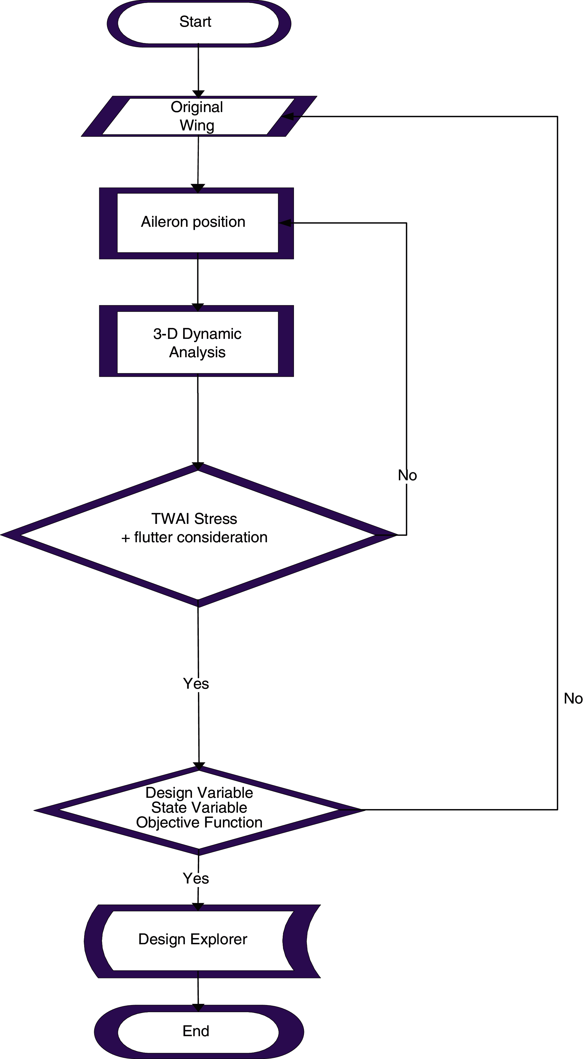
Figure 8: MDO Flow Chart [2]
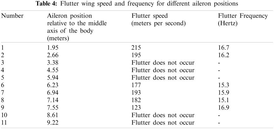
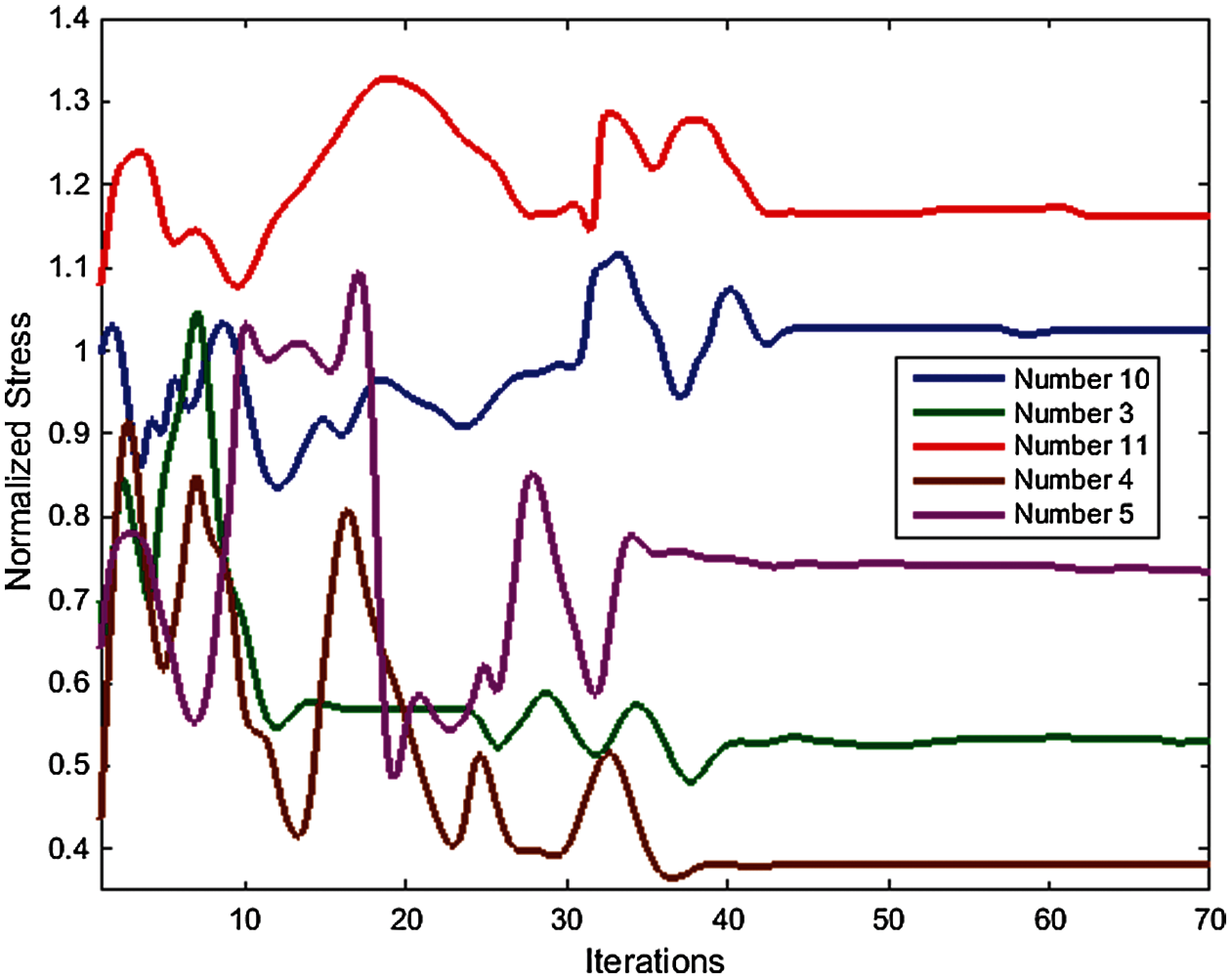
Figure 9: The normalized value of the TSAI–WU criterion during the optimization process
In this study, the effect of aileron position and its critical outcomes on the aeromechanics conditions of composite wing, with a high aspect ratio, were firstly investigated. Given that the speed and frequency of the flutter are directly related to mass distribution, the effects were so dramatic that in some situations the phenomenon of the flutter did not occur at speeds of up to 300 m/s. This study also showed that concentrated mass can be used instead of aileron's total modeling, and it was shown that there is no need to unify the inertial moment of mass inertia and, moreover, only the mass and positions of the center of mass are effective. Finally, based on the USAR [33] and JAR25 [34] critical loading definitions along with of the flutter avoidance criteria, the multidisciplinary optimization method was employed and revealed the best aileron position of composite wing. Therefore, the aileron position can be selected if possible so that the flutter phenomenon does not occur. The results show the flutter speed avoidance is taking place in the prescribed aerodynamic regime of wing and decreasing amount of stress to 50 E5 Pa in root of the composite wing. The design of the represented composite wing regarding nonlinearity effect and free-play of aileron can be an interesting parameter which can be focused on in up-coming studies.
Funding Statement: This work was supported by China Medical University.
Conflicts of Interest: The authors declare that they have no conflicts of interest to report regarding the present study.
1. I. Mahariq, M. Kavyanpoor, M. Ghalandari, M. A. Nazari and D. T. Bui, “identification of nonlinear model for rotary high aspect ratio flexible blade using free vibration response,” Alexandria Engineering Journal, vol. 59, no. 4, pp. 2131–2139, 2020. [Google Scholar]
2. M. Ghalandari, A. Ziamolki, A. Mosavi, S. Shamshirband, K. W. Chau et al., “Aeromechanical optimization of first row compressor test stand blades using a hybrid machine learning model of genetic algorithm, artificial neural networks and design of experiments,” Engineering Applications of Computational Fluid Mechanics, vol. 13, no. 1, pp. 892–904, 2019. [Google Scholar]
3. A. Zeinalzadeh and M. R. Pakatchian, “Evaluation of novel-objective functions in the design optimization of a transonic rotor by using deep learning,” Engineering Applications of Computational Fluid Mechanics, vol. 15, no. 1, pp. 561–583, 2021. [Google Scholar]
4. B. Emslie and A. Goldman, “The effect of backlash and trailing-edge strips on the flutter speed of a two-dimensional model of a tailplane with tab,” the Aeronautical Journal, vol. 86, no. 859, pp. 337–340, 1982. [Google Scholar]
5. H. L. Runyan, H. J. Cunningham and C. E. Watkins, “Theoretical investigation of several types of single degree of freedom flutter,” Journal of the Aeronautical Sciences, vol. 19, no. 2, pp. 101–110, 1952. [Google Scholar]
6. A. Suleman, C. Crawford and A. P. Costa, “Experimental aeroelastic response of piezoelectric and aileron controlled 3D wing,” Journal of Intelligent Material Systems and Structures, vol. 13, no. 2–3, pp. 75–83, 2002. [Google Scholar]
7. P. F. Jacobs, “Aileron effectiveness for a subsonic transport model with a high-aspect-ratio supercritical wing,” Scientific and Technical Information Branch, vol. 5, no. 5, pp. 1–23, 1983. [Google Scholar]
8. Z. Wei, J. Feng, M. Ghalandari, A. Maleki and Z. Abdelmalek, “Numerical modeling of sloshing frequencies in tanks with structure using new presented DQM-bEM technique,” Symmetry, vol. 12, no. 4, pp. 655–667, 2020. [Google Scholar]
9. H. Haddadpour and R. D. Firouz-Abadi, “True damping and frequency prediction for aeroelastic systems: The PP method,” Journal of Fluids and Structures, vol. 25, no. 7, pp. 1177–1188, 2009. [Google Scholar]
10. K. Isogai, “On the transonic-dip mechanism of flutter of a sweptback wing,” AIAA Journal, vol. 17, no. 7, pp. 793–795, 1979. [Google Scholar]
11. E. C. Yates, “Modified-strip-analysis method for predicting wing flutter at subsonic to hypersonic speeds.,” Journal of Aircraft, vol. 3, no. 1, pp. 25–29, 1966. [Google Scholar]
12. M. R. Moosavi, A. R. N. Oskouei and A. Khelil, “Flutter of subsonic wing,” Thin-walled Structures, vol. 43, no. 4, pp. 617–627, 2005. [Google Scholar]
13. S. Li, Y. Zhang and Z. Wu, “Advanced aerodynamic modelling for the optimization of aircraft wing performance via aeroelastic tailoring,” AIAA Journal, vol. 9, no. 20, pp. 1214–1225, 2019. [Google Scholar]
14. D. E. Walshe and T. A. Wyatt, “Bridge aerodynamics 50 years after tacoma narrows-part II: A new discipline world-wide,” Journal of Wind Engineering and Industrial Aerodynamics, vol. 40, no. 3, pp. 327–336, 1992. [Google Scholar]
15. E. H. Dowell, K. C. Hall and M. C. Romanowski, “Eigenmode analysis in unsteady aerodynamics: Reduced order models,” Applied Mechanics Reviews, vol. 50, no. 6, pp. 371–386, 1997. [Google Scholar]
16. K. D. Frampton, R. L. Clark and E. H. Dowell, “State-space modeling for aeroelastic panels with linearized potential flow aerodynamic loading,” Journal of Aircraft, vol. 33, no. 4, pp. 816–822, 1996. [Google Scholar]
17. D. A. Peters, S. Karunamoorthy and W. M. Cao, “Finite state induced flow models. I-two-dimensional thin airfoil,” Journal of Aircraft, vol. 32, no. 2, pp. 313–322, 1995. [Google Scholar]
18. D. H. Hodges, “Review of composite rotor blade modeling,” AIAA Journal, vol. 28, no. 3, pp. 561–565, 1990. [Google Scholar]
19. S. Wang, X. Wang, Y. Wang and H. Ye, “An equivalent damping numerical prediction method for the ring damper used in gears under axial vibration,” Symmetry, vol. 11, no. 12, pp. 1469–1480, 2019. [Google Scholar]
20. A. Shariati, H. Mohammad-Sedighi, K. K. Żur, M. Habibi, M. Safa et al., “Stability and dynamics of viscoelastic moving Rayleigh beams with an asymmetrical distribution of material parameters,” Symmetry, vol. 12, no. 4, pp. 586–601, 2020. [Google Scholar]
21. M. Arena, R. Palumbo, R. Pecora, F. Amoroso, G. Amendola et al., “Flutter clearance investigation of camber-morphing aileron tailored for a regional aircraft,” Journal of Aerospace Engineering, vol. 32, no. 2, pp. 18146–18160, 2019. [Google Scholar]
22. L. Marchetti, A. De Gaspari, L. Riccobene, F. Toffol, F. Fonte et al., “Active flutter suppression analysis and wind tunnel studies of a commercial transport configuration,” AIAA Journal, vol. 10, no. 32, pp. 1677–1681, 2020. [Google Scholar]
23. D. H. Hodges, “Review of” theoretical and computational aeroelasticity,”,” AIAA Journal, vol. 50, no. 4, pp. 990–991, 2012. [Google Scholar]
24. C. Mei, “A finite-element approach for nonlinear panel flutter,” AIAA Journal, vol. 15, no. 8, pp. 1107–1110, 1977. [Google Scholar]
25. D. Y. Xue and C. Mei, “Finite element nonlinear panel flutter with arbitrary temperatures in supersonic flow,” AIAA Journal, vol. 31, no. 1, pp. 154–162, 1993. [Google Scholar]
26. J. Shi and D. Hitchings, “Finite element simulation of gust loading,” International Journal for Numerical Methods in Fluids, vol. 23, no. 11, pp. 1197–1210, 1996. [Google Scholar]
27. S. Mozaffari-Jovin, R. D. Firouz-Abadi and J. Roshanian, “Flutter of wings involving a locally distributed flexible control surface,” Journal of Sound and Vibration, vol. 357, no. 27, pp. 377–408, 2015. [Google Scholar]
28. E. Jonsson, C. Riso, C. A. Lupp, C. Cesnik, J. Martins et al., “Flutter and post-flutter constraints in aircraft design optimization,” Progress in Aerospace Sciences, vol. 127, no. 11, pp. 1–17, 2019. [Google Scholar]
29. H. J. C. Barbosa and A. Lemonge, “A new adaptive penalty scheme for genetic algorithms,” Information Sciences, vol. 156, no. 3–4, pp. 215–251, 2003. [Google Scholar]
30. A. A. Groenwold and R. T. Haftka, “Optimization with non-homogeneous failure criteria like tsai-wu for composite laminates,” Structural and Multidisciplinary Optimization, vol. 32, no. 3, pp. 183–190, 2006. [Google Scholar]
31. P. R. Caixeta and F. D. Marques, “Multiobjective optimization of an aircraft wing design with respect to structural and aeroelastic characteristics using neural network metamodel,” Journal of the Brazilian Society of Mechanical Sciences and Engineering, vol. 40, no. 1, pp. 1–17, 2018. [Google Scholar]
32. M. L. Benzeggagha, K. Khellil and T. Chotard, “Experimental determination of tsai failure tensorial terms Fij for unidirectional composite materials,” Composites Science and Technology, vol. 55, no. 2, pp. 145–156, 1995. [Google Scholar]
33. N. Stanag, “4671 unmanned aerial vehicles systems airworthiness requirements (USAR),” NSA/0976, vol. 1, no. 1, pp. 1–5, 2009. [Google Scholar]
34. I. Mahariq and A. Erciyas, “A spectral element method for the solution of magnetostatic fields,” Turkish Journal of Electrical Engineering & Computer Sciences, vol. 25, no. 4, pp. 2922–2932, 2017. [Google Scholar]
35. I. Mahariq, M. Kuzuoğlu and H. I. Tarman, “On the attenuation of perfectly matched layer in electromagnetic scattering problems with spectral element method,” Applied Computational Electromagnetics Society Journal, vol. 29, no. 18, pp. 701–710, 2014. [Google Scholar]
36. I. Mahariq, H. Kurt, H. I. Tarman and M. Kuzuoglu, “Photonic nanojet analysis by spectral element method,” IEEE Photonics Journal, vol. 6, no. 1, pp. 1–14, 2014. [Google Scholar]
37. I. Mahariq, I. H. Giden, H. Kurt, O. V. Minin and I. V. Minin, “Strong electromagnetic field localization near the surface of hemicylindrical particles,” Optical and Quantum Electronics, vol. 50, pp. 1–8, 2017. [Google Scholar]
38. I. Mahariq, T. Abdeljawad, A. Karar, S. Alboon, H. Kurt et al., “Photonic nanojets and whispering gallery modes in smooth and corrugated micro-cylinders under point-source illumination,” Photonics, vol. 7, no. 50, pp. 1–11, 2020. [Google Scholar]
39. I. Mahariq and H. Kurt, “Strong field enhancement of resonance modes in dielectric microcylinders,” Journal of the Optical Society of America B, vol. 33, no. 4, pp. 656–662, 2016. [Google Scholar]
40. I. Mahariq, H. Kurt and M. Kuzuoğlu, “Questioning degree of accuracy offered by the spectral element method in computational electromagnetics,” Applied Computational Electromagnetics Society Journal, vol. 30, no. 5, pp. 698–705, 2015. [Google Scholar]
41. I. Mahariq, “On the application of the spectral element method in electromagnetic problems involving domain decomposition,” Turkish Journal of Electrical Engineering & Computer Sciences, vol. 25, no.1, pp. 1059–1069, 2017. [Google Scholar]
42. Y. A. Amer, A. M. S. Mahdy, T. T. Shwayaa and E. S. M. Youssef, “Laplace transform method for solving nonlinear biochemical reaction model and nonlinear emden-fowler system,” Journal of Engineering and Applied Sciences, vol. 13, no. 17, pp. 7388–7394, 2018. [Google Scholar]
43. A. M. S. Mahdy, K. Lotfy, W. Hassan and A. A. El-Bary, “Analytical solution of magneto-photothermal theory during variable thermal conductivity of a semiconductor material due to pulse heat flux and volumetric heat source,” Waves in Random and Complex Media, vol. 13, no. 17, pp. 1–18, 2020. [Google Scholar]
44. A. K. Khamis, K. Lotfy, A. A. El-Bary, A. M. S. Mahdy and M. H. Ahmed, “Thermal-piezoelectric problem of a semiconductor medium during photo-thermal excitation,” Waves in Random and Complex Media, vol. 13, no. 12, pp. 1–15, 2020. [Google Scholar]
45. A. M. S. Mahdy, “Numerical solutions for solving model time-fractional fokker--Planck equation,” Numerical Methods for Partial Differential Equations, vol. 37, no. 2, pp. 1120–1135, 2021. [Google Scholar]
46. A. M. S. Mahdy, K. Lotfy, M. H. Ahmed, A. El-Bary and E. A. Ismail, “Electromagnetic hall current effect and fractional heat order for microtemperature photo-excited semiconductor medium with laser pulses,” Results in Physics, vol. 17, no. 859, pp. 103161, 2020. [Google Scholar]
47. M. I. A. Othman and A. M. S. Mahdy, “Numerical studies for solving a free convection boundary--layer flow over a vertical plate,” Mechanics and Mechanical Engineering, vol. 22, no. 1, pp. 41–48, 2018. [Google Scholar]
48. A. M. S. Mahdy, K. Lotfy, E. A. Ismail, A. El-Bary, M. Ahmed et al., “Analytical solutions of time-fractional heat order for a magneto-photothermal semiconductor medium with thomson effects and initial stress,” Results in Physics, vol. 18, no. 1, pp. 103174, 2020. [Google Scholar]
 | This work is licensed under a Creative Commons Attribution 4.0 International License, which permits unrestricted use, distribution, and reproduction in any medium, provided the original work is properly cited. |