DOI:10.32604/cmc.2022.019635
| Computers, Materials & Continua DOI:10.32604/cmc.2022.019635 | |
| Article |
Novel Architecture of OneM2M-Based Convergence Platform for Mixed Reality and IoT
1Department of Computer Engineering and Department of AI Convergence Network, Ajou University, Suwon, 16499, Korea
2Howard R. Hughes College of Engineering, University of Nevada, Las Vegas, NV, 89154, USA
3AST Co. Ltd., Suwon, 16681, Korea
*Corresponding Author: Byeong-hee Roh. Email: bhroh@ajou.ac.kr
Received: 20 April 2021; Accepted: 03 June 2021
Abstract: There have been numerous works proposed to merge augmented reality/mixed reality (AR/MR) and Internet of Things (IoT) in various ways. However, they have focused on their specific target applications and have limitations on interoperability or reusability when utilizing them to different domains or adding other devices to the system. This paper proposes a novel architecture of a convergence platform for AR/MR and IoT systems and services. The proposed architecture adopts the oneM2M IoT standard as the basic framework that converges AR/MR and IoT systems and enables the development of application services used in general-purpose environments without being subordinate to specific systems, domains, and device manufacturers. We implement the proposed architecture utilizing the open-source oneM2M-based IoT server and device platforms released by the open alliance for IoT standards (OCEAN) and Microsoft HoloLens as an MR device platform. We also suggest and demonstrate the practical use cases and discuss the advantages of the proposed architecture.
Keywords: Internet of things (IoT); augmented realty (AR); mixed reality (MR); microsoft HoloLens; oneM2M; convergence platform
The Internet of Things (IoT) has made the world smarter, is continuously evolving, and has pervaded all aspects of life, being more innovative in homes [1–3], factories [4–6], cities [7,8], and so on. IoT services make it possible to monitor and control various sensors and edge devices remotely, autonomously, and in time. With the advances in wireless and mobile technologies, IoT services can be handled on a variety of mobile devices as well as traditional workstation-based systems. However, the information of most IoT services is presented in the form of unspecified dashboards and does not provide intuitive data visualization associated with things, locations, situations, and others. Augmented reality (AR) provides an interactive experience in the real world with computer-generated information using a holographic display. Mixed reality (MR) is a new concept by encompassing virtual reality (VR) and AR [9]. Unlike AR overlaps holograms only in a physical environment, MR allows real-time interaction between physical and virtual environments with various augmented digital information.
The combination of MR with rich visualization related to real objects and IoT with feasible information about things is expected to produce new applications while overcoming limitations. However, IoT has been developed based on standards that interconnect several heterogeneous systems and services, while AR/MR ones are being developed for specific applications tightly coupled with those devices, primarily head mounted displays (HMDs) developed by various vendors in their own ways. These different characteristics between the development processes of IoT and AR/MR may cause interoperability problems when combined and served for common applications [10,11].
There have been numerous works to merging AR/MR and IoT in various ways, which will be explained in detail in Section 2. The studies in [12–24] have dealt with the combination of AR/MR and IoT as essential technologies to support for their specific domains or applications. However, those studies to be applied only to target applications have limitations on interoperability or reusability when utilizing them to different domains or adding new devices to the system. The works adopting common architectures or frameworks using well-known protocols and open sources have been proposed [25–29]. Since the architectural specifications are abstract, conceptual, and ambiguous, they also have a similar problem when service providers intend to use them common to their heterogeneous devices and services.
In this paper, we propose a novel architecture of oneM2M-based convergence platform for AR/MR and IoT systems and services to solve interoperability and reusability problems that existing studies have. Since the proposed architectural concept is to combine machines (or devices) and services from/to IoT and MR, we call the proposed architecture the machine to MR, M2MR in short. The main contributions of the paper are the following:
• The proposed architecture adopts the oneM2M IoT standard [30] as the basic framework that converges AR/MR and IoT systems and enables the development of application services used in general-purpose environments without being subordinate to specific systems, domains, and device manufacturers.
• The proposed architecture can provide intuitive interfaces and usages to users by exchanging data complying with oneM2M IoT standard between MR and IoT systems and applications.
• We implement the proposed architecture utilizing the Mobius and the nCube as open-source oneM2M-based IoT server and device platforms, respectively, released by the open alliance for IoT standards (OCEAN).
• Besides, we consider Microsoft HoloLens as an MR device platform and add oneM2M device interface by modifying the nCube platform in it.
• We suggest and demonstrate the practical use cases of the proposed architecture, then give the discussion about the advantages of the proposed architecture.
The remainder of this paper is organized as follows. In Section 2, backgrounds on the proposed method are described. The proposed architecture and implementation are presented in Section 3. In Section 4, the validation of the proposed architecture is given. In Section 5, discussions on the case studies and the advantages of the architecture are illustrated. Finally, Section 6 concludes the paper.
2.1 Related Work on Merging AR/MR and IoT
Many studies have been conducted to augment IoT information to AR/MR devices for specific applications and domains. Belen et al. [12] demonstrated a smart home system for elderly people using Microsoft HoloLens with four key functions: object recognition, sensor monitoring and control, and navigation. Mahroo et al. [13] implemented a simple AR application for a smart home using HoloLens and Arduino. This system operates without an IoT or cloud server that stores data. Pargmann et al. [14] proposed a plant management system that displays the global status of wind farms. They focused on implementing digital twin technology by converging AR and IoT. In a smart city domain, Zhang et al. [15] overlaid various types of city data on a virtual city model and evaluated them through a questionnaire. Using a method similar to that used in [14], they also attempted to build a digital twin with HoloLens. Rashid et al. [16] proposed an AR–IoT environment that makes it easy for people with disabilities to access information in the context of a smart city. Jang et al. [17] proposed a building management system using MR. Mylonas et al. [18] built an AR application that monitors IoT data with the goal of energy management in a school building. Jo et al. [19] presented a combined system of AR and IoT targeting shopping experience. However, in the process of validating the usability of their model, they implemented only part of the system. In terms of smart factories, Mizutani et al. [20] provided the use case of their HoloInventory system, which allows role-specific access for industrial managers and technicians to different information sources. For robot monitoring, Guhl et al. [21] proposed an “interaction layer–broker–robot layer” architecture similar to typical IoT architecture. In addition, they used HoloLens providing more intuitive experience to users with sound and vibration. Hoppenstedt et al. [22] developed a Message Queuing Telemetry Transport (MQTT)-based monitoring system for the density distribution of a fuel cell. In this system, HoloLens is used as the MQTT client to display the state of the fuel cell. Stark et al. [23] presented an IoT monitoring and control service for mechatronic devices. The service runs on mobile devices and interacts with mechatronic devices using a commercial computer vision kit. Park et al. [24] proposed a JARVIS system architecture that receives information from a real-time motion analysis engine and exercise equipment applied to MR in fitness coaching and provides the current exercise status and information. Phupattanasilp et al. [25] presented an integrated architecture to utilize AR for data visualization in IoT and monitoring applications overlaying crop parameters as a case study.
These works mainly focused on the implementation in specific situations or elementary technologies. Although few of them dealt with architecture or platform, their output also had domain dependency. For example, [20] and [21] proposed their own architecture based on the robot operating system (ROS), a middleware for the robotics domain. [25] introduced the AR–IoT system but mainly highlighted measuring three-dimensional (3D) coordinates with multiple cameras.
Several studies have considered the IoT architecture for integrating MR and IoT. Martin et al. [26] proposed a system architecture for the communication of various VR/AR devices in an IoT environment by defining data transfer objects and data transfer rules. Koutitas et al. [27] implemented a VEoT system that visualizes the network topology connected between real devices through the combination of an IoT device and an MR device; it visualizes the measured information through sensors such as the surrounding network signal intensity in real time. Croatti et al. [28] proposed an agent-based MR–IoT platform that can control physical objects physically and dynamically create a virtual object in the MR system. Blanco-Novoa et al. [29] presented an MR–IoT framework using standard and open-source protocols and tools such as MQTT, Hyper Text Transfer Protocol (HTTP), or Node-Red.
However, they only pertain to implementation-level standards and protocols, which are conceptual and ambiguous for commercial use. Hence, our study progresses toward applying well-known IoT standards instead of specifying entire practices in the IoT architecture. Among the standards, we choose the oneM2M standard, which is open-sourced and well designed for application developers.
2.2 Overview of OneM2M IoT Standard
The primary goal of oneM2M is to unify fragmented IoT ecosystems that operate industrially. This project has defined requirements, architecture, API specifications, security solutions, and interoperability for IoT. To provide for multivendor interoperability, the architecture provides a vendor-independent middleware consisting of common service functions (CSFs) commonly required in IoT services. In addition, CSFs allow the application developer to focus on IoT applications. The list of CSFs are Registration, Communication Management and Delivery Handling, Data Management and Repository, Device Management, Application and Service Layer Management, Discovery, Group Management, Subscription and Notification, Location, Network Service Exposure, Service Execution, and Triggering, Security, and Service Charging and Accounting.
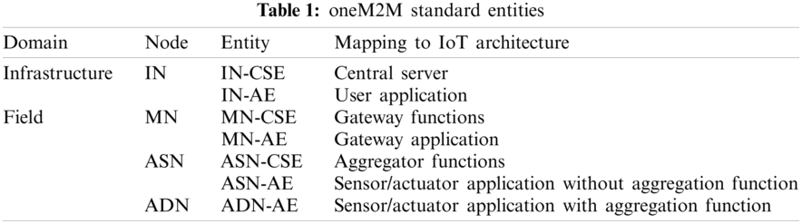
Tab. 1 shows oneM2M entities and their mapping elements in typical IoT architecture. To pattern the typical IoT architecture to the oneM2M standard, all objects in the oneM2M architecture are defined as reference models that belong to two domains: infrastructure and field domains. The infrastructure domain refers to the domain in which servers and applications reside on larger computers, and the field domain refers to the domain in which sensors, actuators, aggregators, and gateways are deployed. Each domain contains multiple nodes, which are logical objects hosted on the physical device. Nodes consist of two entities: application entity (AE) and common service entity (CSE). CSE is a set of CSFs, and AE is an IoT application. Based on domains and entities, nodes can be classified into four categories. Infrastructure node (IN) contains one CSE and multiple AEs. IN-CSE is hosted in the cloud by the oneM2M service provider. IN-AE is a user application embedded in a mobile device or a personal computer with capabilities to interact directly with the IN-CSE. Middle nodes (MNs) are deployed on IoT gateways. MN-AE is a gateway application, and MN-CSE provides CSFs to MN-AE. Both the application service node (ASN) and application dedicated node (AND) can be mapped to an application embedded in a sensor or an actuator. The difference between them is that ASN contains CSE, but ADN does not contain CSE. Therefore, ADN includes only AE, and the MN-CSE takes over the function of aggregating data.
In oneM2M standard, communication between entities is defined as a reference point. M2M communication with AE (Mca) reference points refer to communication flows between CSE and AE. Similarly, M2M communication with CSE (Mcc) reference point refers to communication flows between two CSEs. The oneM2M primitives are service layer messages transmitted over the reference points. They follow a representational state transfer (REST) architecture style that allows requesting systems to create, retrieve, update, and delete (CRUD) data to access resources. This style provides ease of use and interoperability to developers and can bind to multiple protocols such as HTTP, Constrained Application Protocol (COAP), and webSocket.
In a typical IoT architecture, the entire data is stored in a database on a central server and the user can access the information of the entire system by only interacting with the server. In oneM2M, IN-CSE stores data from all entities such as CSE and AE in a hierarchical structure. In oneM2M architecture, each entity is represented as a resource and consists of multiple attributes and child resources. Attributes refer to a set of information related to the resource, such as identifiers, tags, creation and update times, groups, and values. In addition, each resource has a unique and addressable URI to access the RESTful system.
There are various resource types defined in oneM2M; the following three types are essential to map oneM2M to the context of an IoT system: CSEBase (CB), Container (CN), and ContentInstance (CI). CB is a root resource, which contains the entire resource as a descendent. CN refers to the virtual space to which the data instance belongs. This type can be mapped to locations such as buildings, offices, and rooms, as well as devices such as sensors and actuators. CI is an actual data instance from end devices, sensors, and actuators. Fig. 1 illustrates an example of resource management for a simple IoT system with a temperature sensor and its switch. Similar to the physical architecture, IN-CSE runs a database where CSE contains CN Room1, tempSensor and switch as subdirectories. AND-AEs updates their sensor states with creating new CI on CN. That is, multiple CIs are stored and IN-CSE provides the retrieval function of latest content CI.
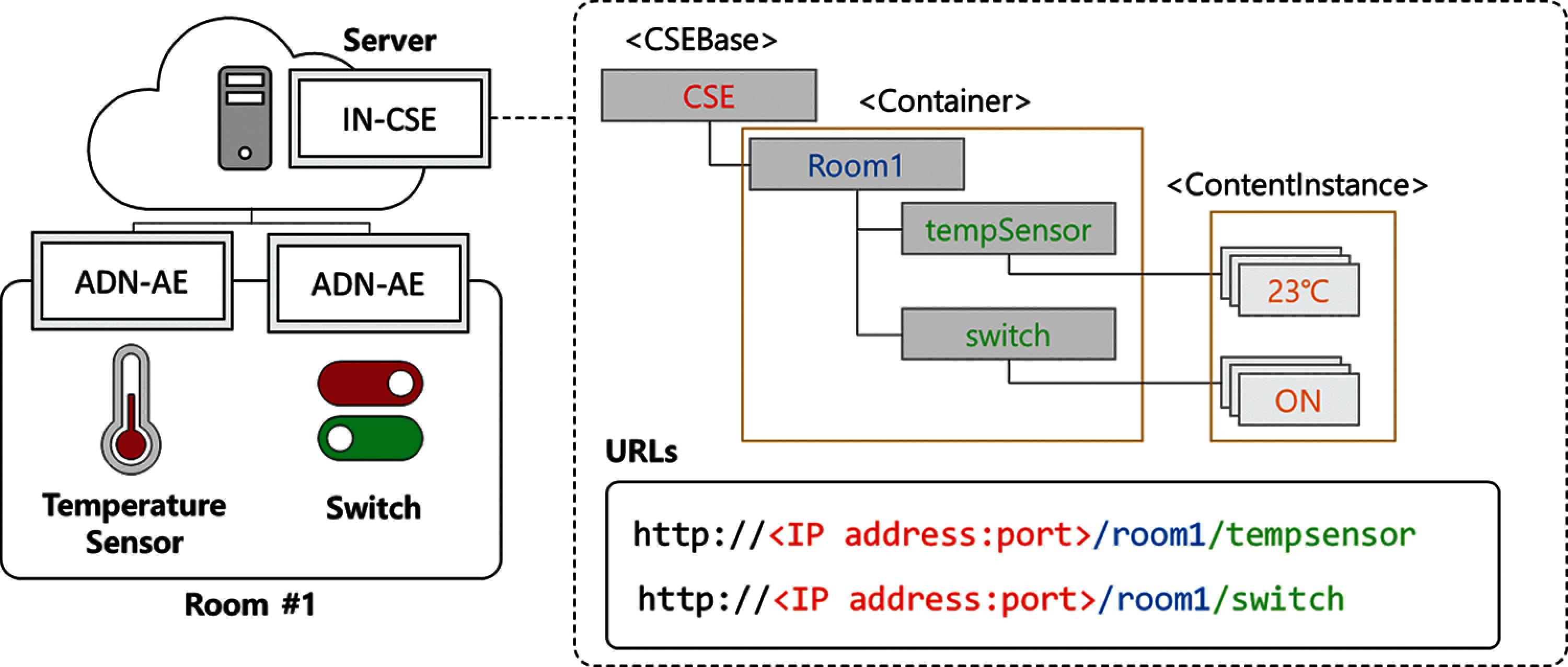
Figure 1: Resource management example for oneM2M service
3 Machine-To-Mixed Reality (M2MR): oneM2M-Based Convergence Platform for AR/MR and IoT
This section explains the architecture of the oneM2M-based convergence platform for AR/MR and IoT, called M2MR. First, the requirements for M2MR design are described. Then, the overall system design and procedure are presented. Finally, the implementation of M2MR with the Microsoft HoloLens and the open-source oneM2M-based IoT platforms by OCEAN is illustrated.
The most typical application domains and functions commonly considered in exiting studies on adapting AR/MR in association with IoT systems are shown in Tab. 2. As listed in Tab. 2, M2MR can be applied to numerous areas for making home, city, building, industry, factory, and so on, smarter with practical functions such as object tracking, data monitoring, actuator control, and MR data transmission. The requirements for most promising functions are as following:
Object Tracking: MR devices should recognize the physical objects the user is staring at. Typical IoT dashboard systems should display data with several visualization methodologies such as tables and graphs, which are unnecessary to understand the context of the physical surroundings. In the contrast, to bring real objects to virtual environment, understanding the surrounding contexts is essential. This requirement is closely related to others, as object tracking must precede data monitoring and actuator control.
Data Monitoring: IoT systems should have the capability to present abstract data gathered and analyzed from various sensors, devices, and others connecting to them on screens as dashboard styles. When MR devices are involved with IoT, the data should be displayed and manipulated on MR screen by overlaying holograms with the surrounding physical context.
Actuator Control: IoT systems should have the capability to control actuators as well as sensors, devices, and others connecting to them. Commonly, IoT dashboard systems are serviced on workstations or mobile devices with a mouse, keyboard, or touchscreen. As a new type of user application, MR devices should provide the control interfaces with their own input system such as hand motion and speaking. For example, holographic buttons are overlayed on the physical objects and user can interact with them.
MR Data Transmission: The data produced from MR devices should also be managed and monitored in IoT systems. In other words, MR devices should send their own data to IoT Server as sensors in the field. For example, the data should be sent when the user initializes the system (e.g., basic information, who is using it, what is his/her job, etc.) or periodically after initialization (e.g., location and image).
Fig. 2 shows the overall system design of M2MR based on the oneM2M standard architecture. This architecture is divided into two parts: IoT Platform and MR Platform.
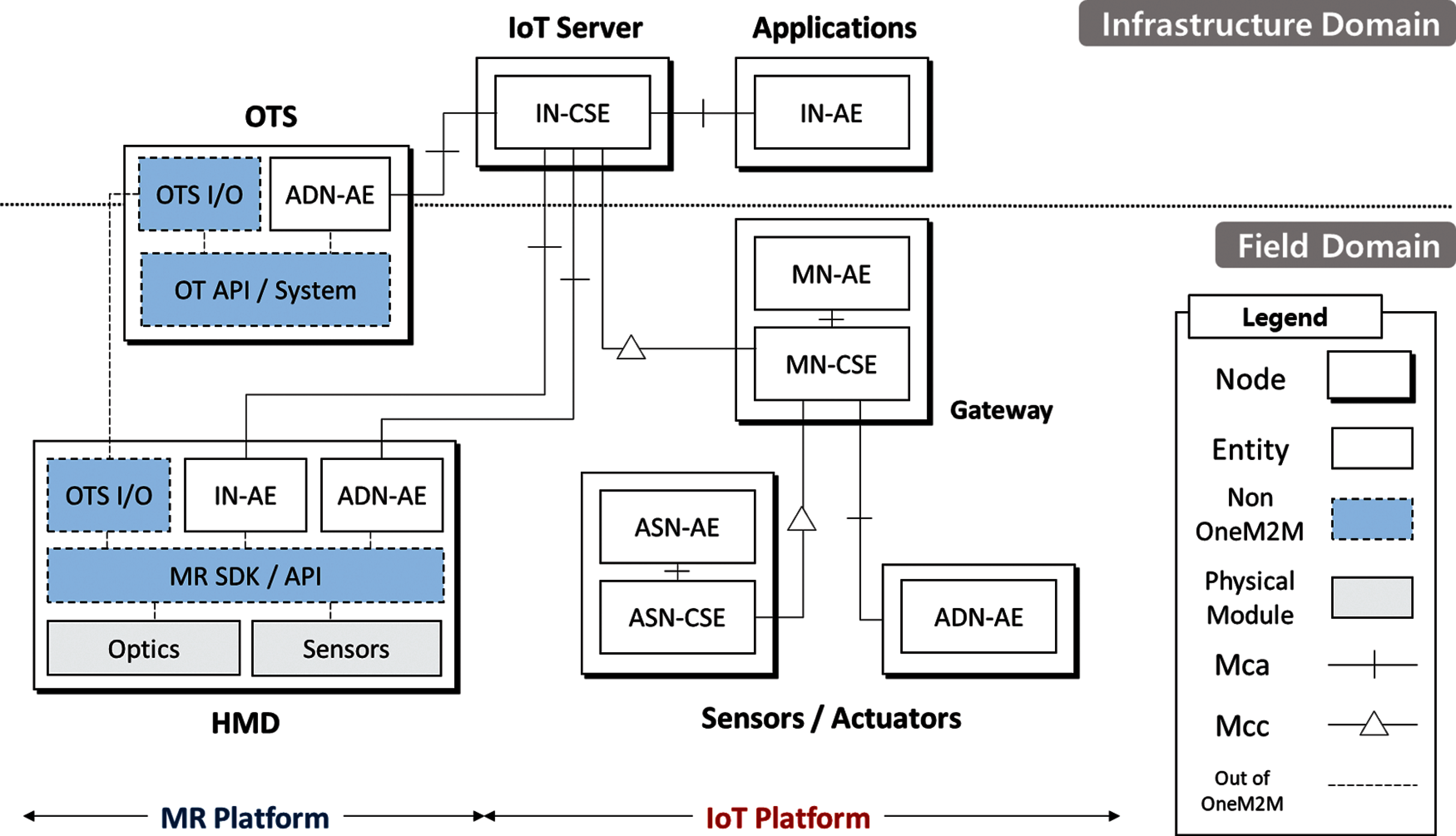
Figure 2: oneM2M based system architecture
IoT Platform: the IoT platform consists of servers, gateways, sensors, actuators, and user applications similar to the existing oneM2M ecosystem. In the infrastructure domain, there are the IoT server containing IN-CSE, and the user applications containing IN-AE. In the field domain, the gateway node consists of MN-AE and MN-CSE. Sensor and actuator nodes are defined as either ASN or ADN depending on whether they contain the CSE.
MR Platform: The MR platform consists of HMD and the object tracking system (OTS). MR devices are typically best thought of as HMD and placed in the field domain. OTS is designed to support object tracking for HMDs and can be deployed in either in the field or infrastructure domain.
HMD (Head Mount Display): In HMD, there are two types of hardware modules: optics for supporting see-through display and various sensors for surrounding recognition, such as a color camera, depth camera, microphones, and inertial measurement unit (IMU) sensors. To access these hardware modules, developers are provided with software development kits (SDK) and application programming interface (API). According to the oneM2M specification and requirements, the HMD translates to a single node that contains OneM2M device interfaces, IN-AE and ADN-AE, and does not contain CSE. The IN-AE connects to IN-CSE to monitor and control surrounding sensors and actuators. The ADN-AE in HMD connects to IN-CSE and MN-CSE to transmit data produced from HMD sensors, similar to other connected devices. In addition, OTS Input Output Module (OTS I/O) sends image data to OTS and receives the tracking results from OTS.
OTS (Object Tracking System): OTS contains three entities; OTS I/O, ADN-AE, and OT Platform. OTS I/O preprocesses the received image and post-processes the result such as decompressing, relaying, and returning the results. Optionally if storing the OT results is required for the future usage, ADN-AE sends them periodically to the IoT server. Lastly, OT platform provides actual function for object tracking.
To build the OT platform, developers should choose one of two methods to track the real objects: marker-based (MB) and marker-less (ML). The marker refers to a specific image pattern; MB-OTS maps a predefined pattern to images captured by a camera on the HMD. ML tracking refers to all techniques that exclude markers such as simultaneous localization and mapping (SLAM), deep learning-based object detection, and geographic information. Either MB-OTS or ML-OTS can be selected according to several considerations. Computing power is one of the essential considerations, because usually MB-OTS consumes less computing power than ML-OTS. To overcome the lack of the power, OTS can be placed on the cloud instead of running on the HMD. In this case, network latency is also another essential metric because the systems must guarantee real-time.
To design the M2MR architecture that guarantees the requirements, we derived detailed procedures for each requirement with sequence diagrams illustrating how entities interact with each other. Fig. 3 demonstrates in detail the step of the requirements.
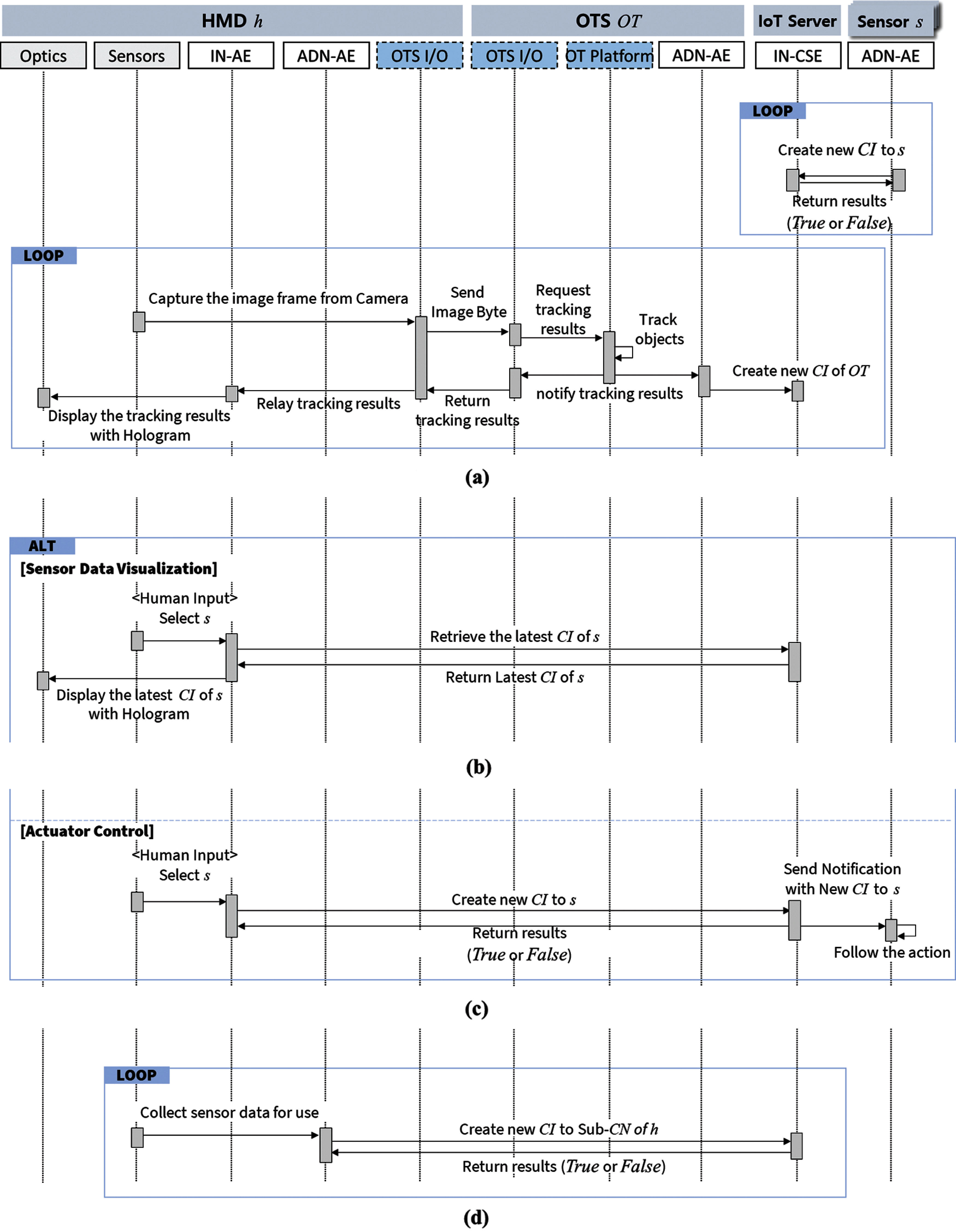
Figure 3: Sequence diagram of M2MR architecture. (a) Object tracking (b) Data monitoring (c) Actuator control (d) MR data transmission
Let us assume that there is the HMD h, and the sensor s in the same field. Independently, the IoT platform periodically collects data from connected sensors including s. That is, the AE of s sends a request message including the sensor value repeatedly. When IN-CSE received the message from s, it creates a new CI as the received value, under the s's CN and responds to s with the result of whether it was successfully updated. In the figure, MN and ASN are omitted.
Object Tracking: As shown in the Fig. 3a, the object tracking step should precede for sensor data visualization and actuator control. First, the image frame is captured from a RGB camera, one of the sensors. Then, OTS I/O of h sends the converted frame as a byte array to OTS I/O in OT. OT platform runs the object tracking algorithm and then notifies the tracking result including the object labels and coordinates on the image to OTS I/O and ADN-AE. OTS I/O returns it to OTS I/O of h and ADN-AE creates a new CI to OT's CN in IN-CSE. The IN-AE of h receives the result and displays the tracking result on the optics of h with a holographic user interface such as hovered buttons and text.
Data Monitoring: The Fig. 3b shows the procedure of data monitoring. When h detects s, IN-AE in h provides user interfaces such as holographic texts or button on optics. When it is triggered by any user command, IN-AE requests a retrieve message to IN-CSE, and it returns the latest CI of s. Then, IN-AE displays it with holographic type on optics.
Actuator control: Fig. 3c illustrates the procedure of actuator control. Typically, most sensors also contain an actuator such as an ON/OFF switch. Therefore, s also denotes the actuator in the figure. Similar to data monitoring, h tracks surrounding actuators with OTS. When h detects s, IN-AE in h provides user interfaces such as holographic texts or the button on optics. Unlike data monitoring, IN-AE creates the new CI to the CN of a when there is user inputs. IN-AE makes CI according to message type and protocol and send request packet to IN-CSE.
MR Data Transmission: Fig. 3d shows the sequence of MR data transmission. h produces specific data for use from sensors or itself and ADN-AE of h sends them to create a new CI in the sub-CN of h. The iteration is decided by the attributes of the data. Initial information, such as user information or tasks, for example, is sufficient for one iteration. There is also information that is repeatedly collected. For example, when the HMD has a GPS attached, ADN-AE periodically creates CI with its location.
To build an IoT environment, we used the open-sourced platforms by OCEAN, which is responsible for releasing the platforms certificated by oneM2M. Each entity in our architecture runs the OCEAN's open-sourced platform corresponding to its own type as follows: IN-CSE platform Mobius, AE platform nCube Thyme, ASN-CSE platform nCube Lavender, and MN-CSE platform nCube Rosemary. We built IN-CSE with the oneM2M server platform, Mobius 2.4.X, and MySQL-based database on a personal computer. For Windows system, we used MySQL, and for the Linux (Ubuntu) system, we used MariaDB. Nodes in the field domain were deployed on Raspberry Pi 3 and 4. Every platform we used was implemented with Node.js.
Reference points were set as follows as the default values of Mobius and nCube. Sensors and actuators interact with nCube Thyme through the socket. Between CSE and AE in the field domain, MQTT is the primary communication protocol. nCube Thyme publishes sensor data with its own MQTT topic and Lavender or Rosemary subscribe it. For the actuator data, it is vice versa. Mosquitto was used for the MQTT service. The reference points of Mobius are HTTP Requests with REST API.
We chose Microsoft HoloLens for the MR device. The initial output was developed with HoloLens 1, and the output was developed with HoloLens 2 after the release. Because there is no service to interact with oneM2M in HoloLens, we implement the application consisting of two AEs using Unity, one of the most popular game development tools. Both AEs in HoloLens connect to IN-CSE with HTTP.
OTS has been implemented in various ways, which will be covered in the next section with practical applications. The reference point between ADN-AEs in OTS and HoloLens also depends on implementation.
3.4.2 Component Based Development
A component refers to a module or service that performs an independent task; component-based development is an approach to developing and assembling it [31]. Therefore, developers can reuse it repeatedly in multiple applications that require it.
Fig. 4 illustrates a layer architecture diagram of the HoloLens application derived from the architecture. The actual implementation is more complicated; however, the diagram is abstracted. It is composed of four layers: components, open sources, development platform, and hardware.
The hardware layer consists of optics and sensors, and the input and output hardware. In the development platform layer, Windows OS kernel services and the HoloLens interaction services are abstracted to the Windows Universal Windows Platform (UWP). For instance, identifying gestures and voice is one of the HoloLens interaction services pre-developed in Windows UWP.
The open-source layer consists of a Mixed Reality Toolkit (MRTK) and other open sources running on Unity. MRTK is supported by Microsoft to develop VR/AR/MR windows applications. Various services of MRTK are used to develop HoloLens applications, such as camera handlers, input handlers, and scene managers. However, only the REST and UX building blocks are shown in the diagram because the components reference and use them primarily as external libraries. Other open sources include object pool, HoloLens CameraStream, and SimpleJSON. Object pool is a set of scripts that implement the object pool design pattern. This pattern is used to improve performance with pre-instantiated ready-to-use objects on a pool instead of creating new objects whenever required. HoloLens CameraStream is the Unity plugin that makes the HoloLens video camera frames available to a Unity app in real time. SimpleJSON provides serializing (building) and deserializing (parsing) JSON type messages in C#.
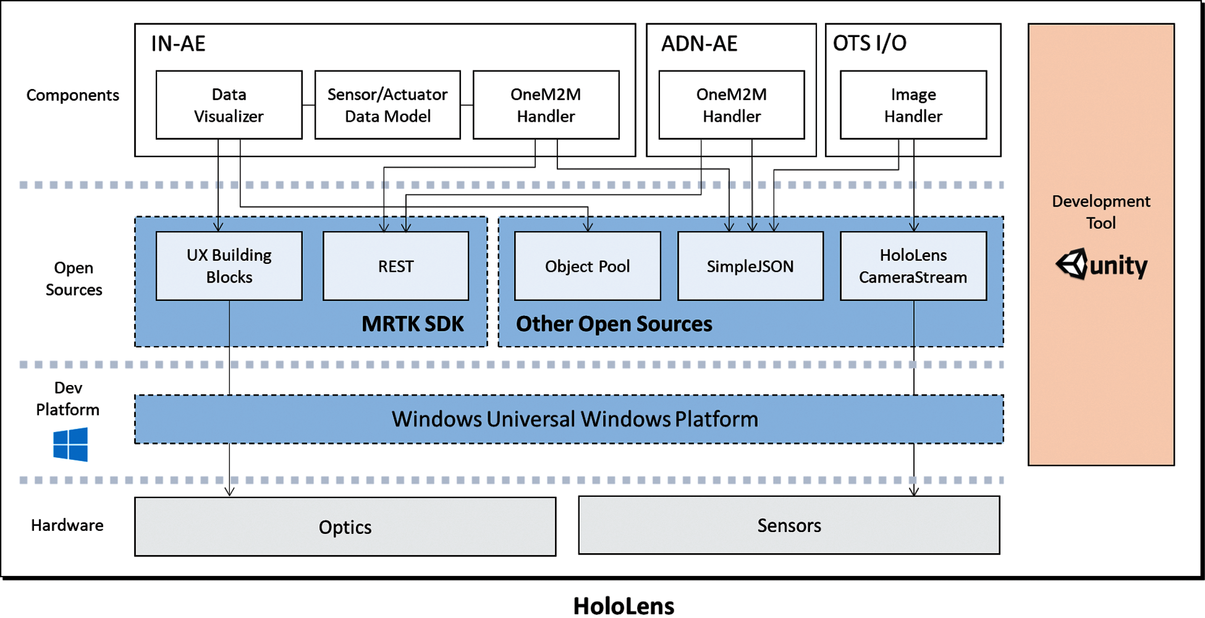
Figure 4: Layer architecture of HoloLens application
The component layer is described by dividing it into three entities according to the proposed architecture. IN-AE consists of a data visualizer, sensor/actuator data model, and oneM2M handler. The data visualizer displays holographic objects on a see-through screen using UX building blocks. Because holographic objects depend on the performance of the HoloLens CPU and GPU, dynamically created UI objects are managed as an object pool. The sensor/actuator model refers to data type and logic to manipulate IoT sensors and actuators. The model is referenced by both the data visualizer and the oneM2M handler. The oneM2M handler includes Web Request methods to Mobius based on MRTK REST. Similarly, ADN-AE contains the oneM2M handler to update MR data to IN-CSE. OTS I/O contains image handler that encodes an image byte array using HoloLens CameraStream, sending it to OTS and receiving the tracking result.
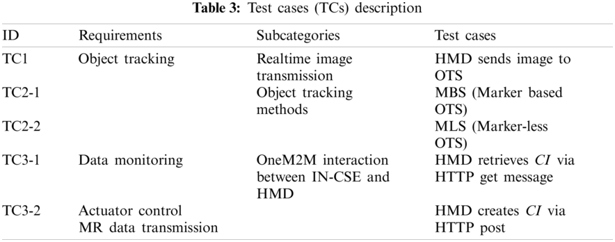
In this section, experiments and results are described to verify our architecture, M2MR and prototype. Tab. 3 shows the defined test cases grouped with requirements. Each test case includes at least one question to be determined as Pass–Fail.
The experimental environment is equivalent to the system environment of the prototype. IN-CSE was run on Windows 10. MBS runs as a component on HoloLens 2 and MLS runs independently on Ubuntu OS. In addition, nodes communicate through 802.11ac in the local area network.
4.1 TC1: Image Streaming for OTS
Because image streaming is a feature that delivers video content, it is difficult to describe whether streaming works. Instead, the captured image from the HMD and the picture in the third person are compared. Therefore, there is no allowance for the metric; however, pass/fail is decided based on human perception and experience.
Streaming service was required to prove that the image was successfully delivered to the OTS. We implemented a Unity application including the function to decode byte arrays into an JPH format. In addition, communication between HMD and OTS is developed with a TCP socket sending byte array.
Fig. 5a displays the third person's view of the HMD and the target object, another HMD. As shown in Fig. 5b, the target object is in the center of the client screen. We recognize that the HoloLens’ FOV is being streamed properly compared to the third person view of the HMD. As a result, it was determined that TC1 passed.
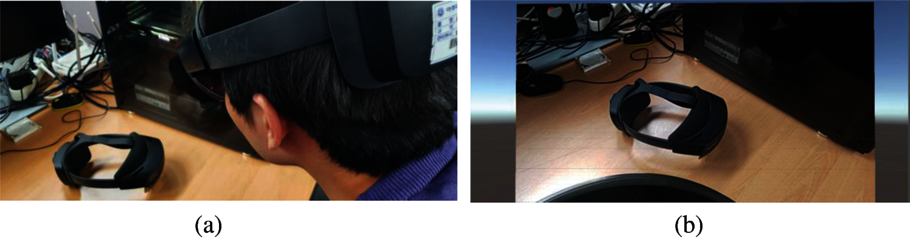
Figure 5: Experimental results for TC1 (a) Third person view of HMD and the target object (b) Unity client for image viewer from HMD
4.2 TC2: Object Tracking: MBS and MLS
The test case aims to verify the OTS, including MBS and MLS. We implemented the MBS with quick response (QR) code tracking running in HMD and MLS with convolutional neural network (CNN) based object tracking running on the remote server. MBS was implemented through Vuforia, one of the most popular marker-based AR SDKs, and MLS was implemented with TensorFlow. Similar to TC1, it verifies the system through the screen capture of the actions from the outputs.
Fig. 6 shows the captured image of tracking a QR code on the HMD. By moving and rotating QR codes, we accepted that QR tracking is working properly and considered the first question as passed. The metric and allowance of the second question is more similar to that of TC2 than MBS. We compared the third-person view shown in Fig. 7a and the object tracking result shown in Fig. 7b. As a result, it was confirmed that the implementation of MLS is verified.
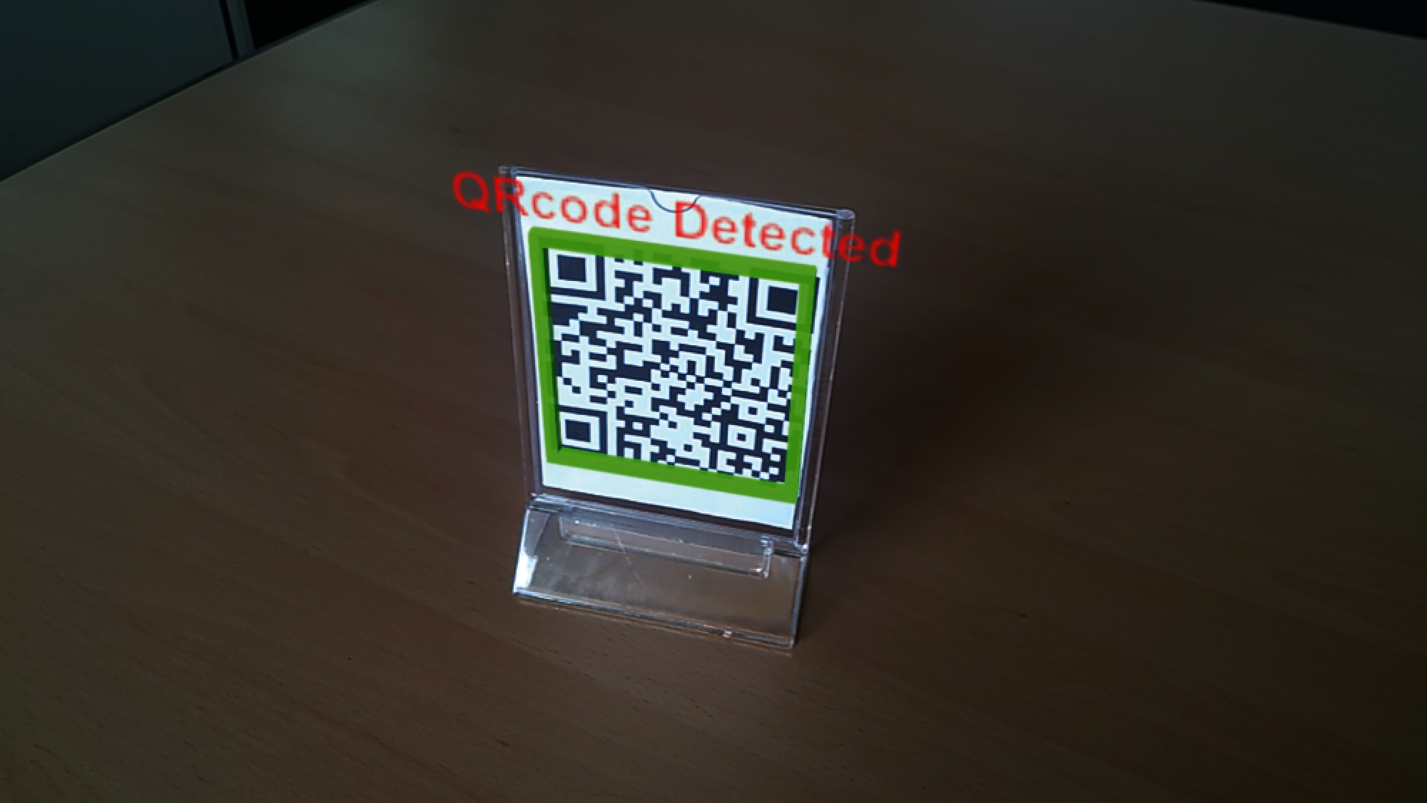
Figure 6: Experimental result for TC2-1: QR code-based OT in MBS
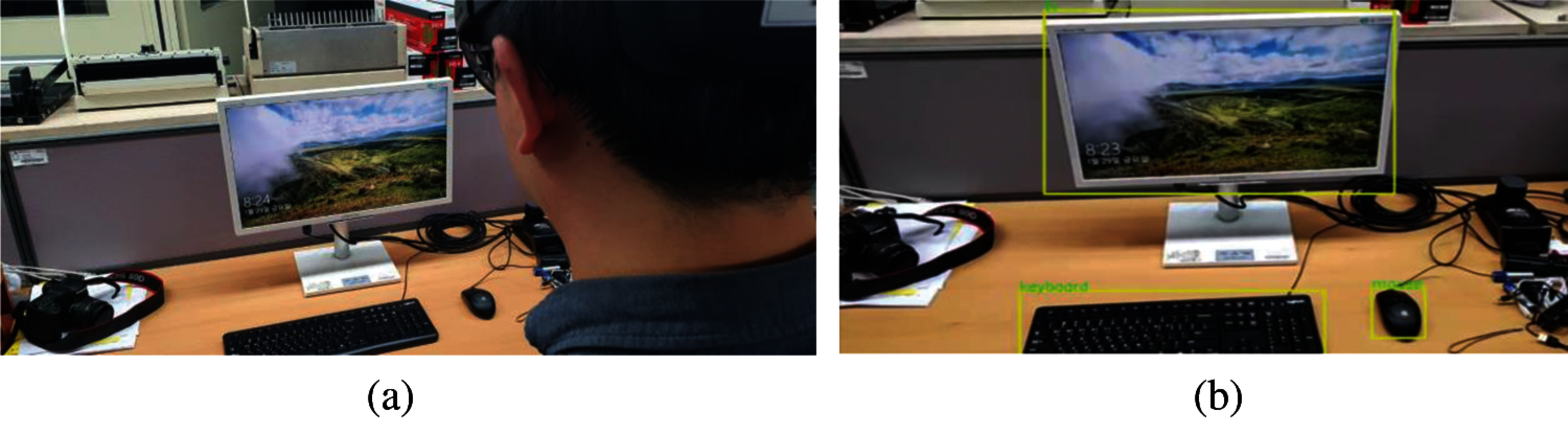
Figure 7: Experimental results for TC2-2: CNN-based OT in MLS (a) Third person view of HMD and target objects (b) OT results in MLS
4.3 TC3: OneM2M Interaction Between in-CSE and HMD
The purpose of TC3 is to prove that the interaction between oneM2M and HMD is working properly. Two subcases are listed to determine whether it has been successfully verified: TC3-1 is for sensor data visualization and TC3-2 is for actuator control and MR data transmission. For both cases, the rate of HTTP response messages to HTTP request messages was selected as a metric. The successful responses to all requests, “200 OK” for HTTP Get and “201 Created” for HTTP Post, can be considered appropriate for implementing the two interactions. Therefore, it was hypothesized that the number of request packets and the number of successful response packets would be the same. Because network performance is not considered, the metric allowance is set to 100%, which does not fail. To show this more effectively, the interval between HTTP messages is reduced from 1,000 milliseconds to 1 millisecond. That is, the number of packets per second increases exponentially.
Figs. 8 and 9 represent the results of questions TC3-1 and TC3-2, respectively, with the rate of response packets to requests. The number of HTTP request messages GET and POST is expressed in lines, and the number of valid HTTP response messages is expressed in symbols. Because the symbols are located on the line, it was confirmed that the request packet and the response packet were properly transmitted and received. Therefore, the test case can be considered as verified.
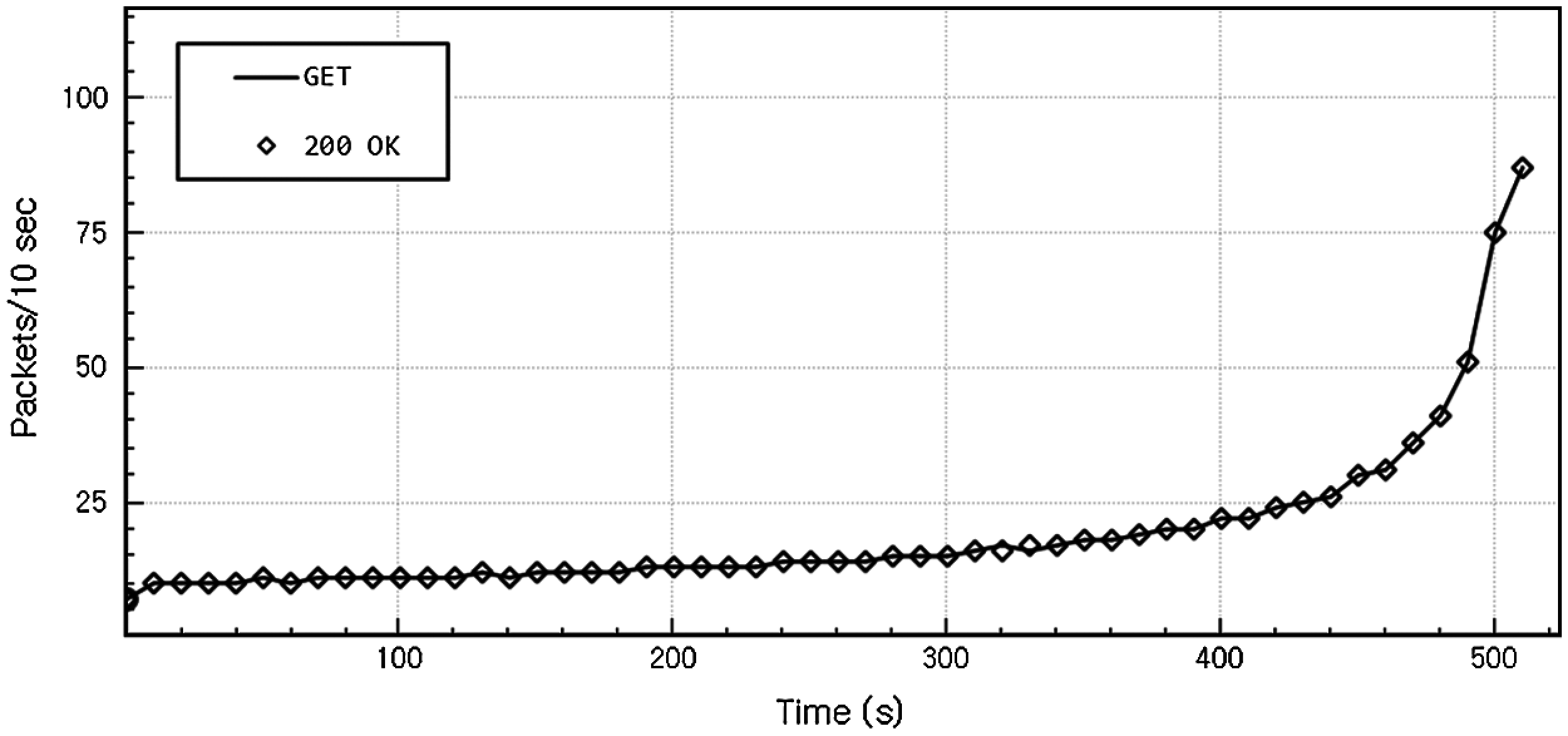
Figure 8: Experimental results for TC3-1: 200 OK message rates per GET message
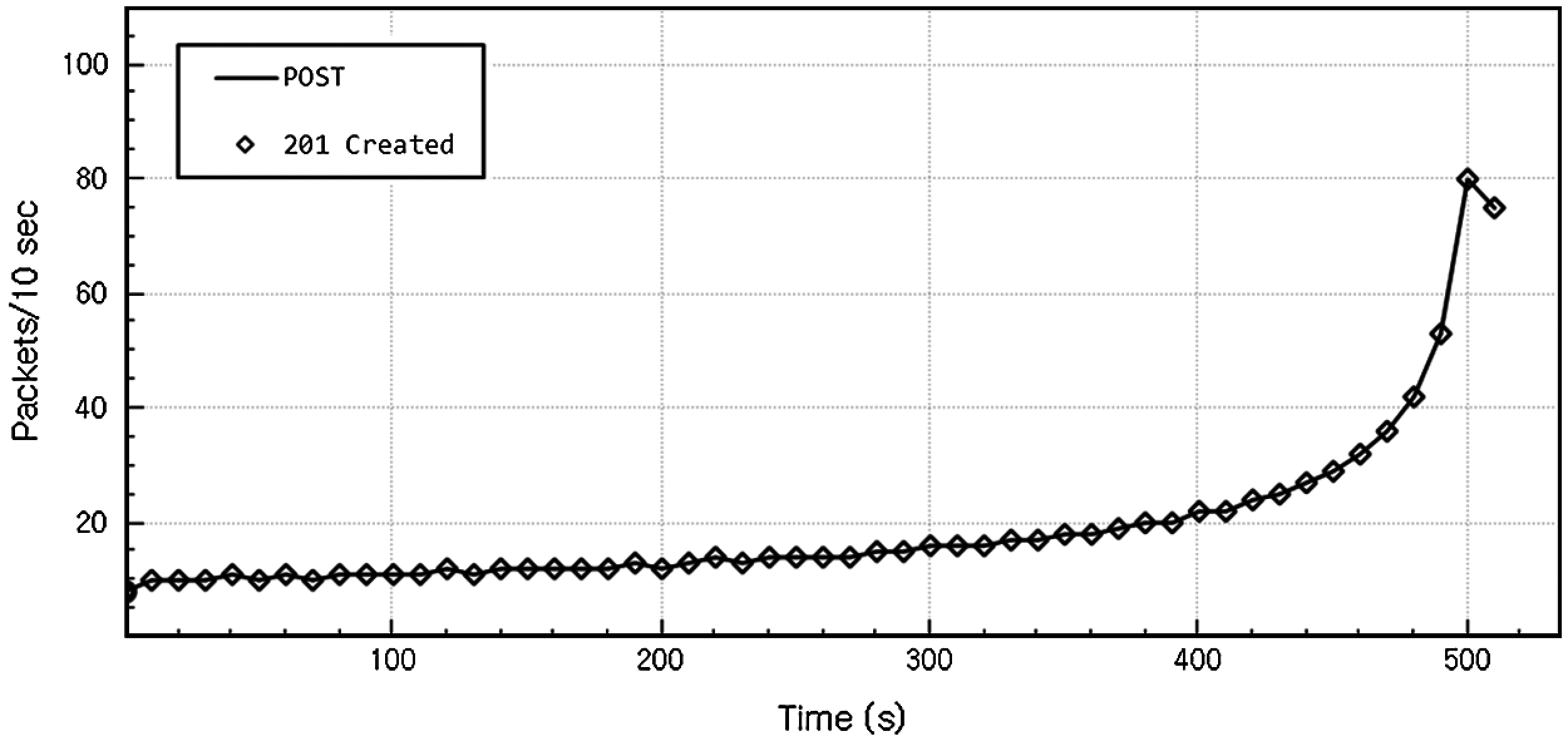
Figure 9: Experimental results for TC3-2: 201 created message rate per post message
To ensure the feasibility of our architecture, M2MR and its implementation, two practical IoT applications are demonstrated in this section. The first application [32] is a marker based IoT system that consists of a single temperature and humidity sensor, IoT server and HMD, and HoloLens. The second application is the marker-less IoT system satisfying all workflows. In the system, CNN-based object recognition identifies the sensors and actuators of the HoloLens’ FOV.
5.1.1 Marker-Based M2MR System
This is based on our first IoT application using the Mobius platform and HoloLens presented in January 2018. OneM2M sensor data retrieval and actuator control functions were simply implemented as a HoloLens application. This application used MBS with Vuforia for OTS. Fig. 10 shows the demonstration of the HoloLens application. The server platform, that is, Mobius Yellow Turtle 2.0.0, was installed on the Windows PC as IN-CSE. The DHT11 humidity/temperature sensor connects to Raspberry Pi 3 as the ADN-AE Raspberry Pi connects the server with ethernet directly. When the HoloLens is detected by the marker, temperature and humidity values are displayed blended around the sensors. In this case, we first used the Raspberry Pi image as a marker, but with a low recognition rate. We used the QR code. On/Off Buttons are also displayed next to the values and used when the IoT server starts or stops to collect sensor data.
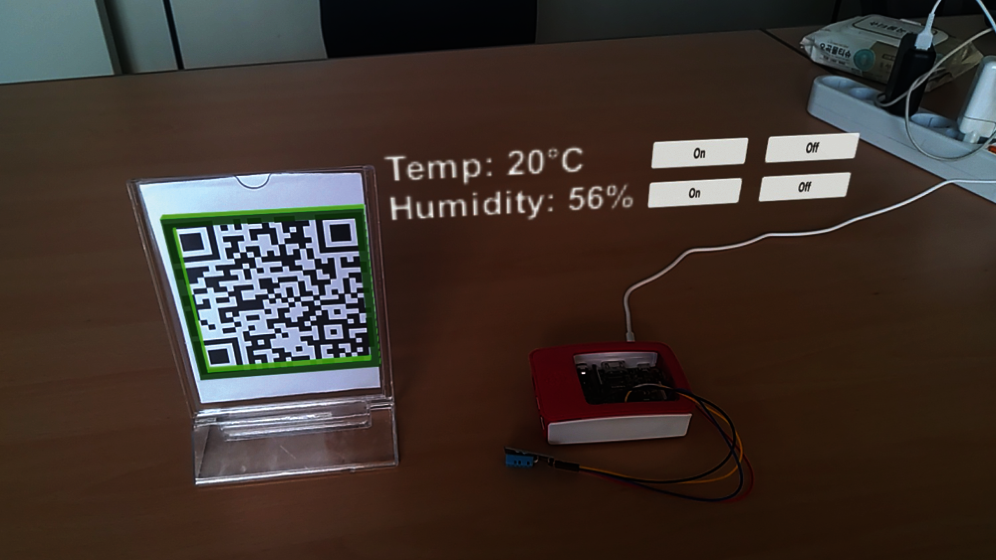
Figure 10: Marker-based M2MR System
This system is a marker-less based IoT system that satisfies all requirements. In addition, the HoloLens application in this system follows the component layer architecture. We used the latest versions of IoT platforms, Mobius 2.4.36 and nCube Thyme 2.3.2. As a marker-less based system, the object tracking system runs in the infrastructure domain. We used HoloLens CameraStream to capture images and sockets to send them as a byte stream. MLS runs the faster R-CNN model [33] on the TensorFlow platform to detect sensors and actuators.
Fig. 11 shows the demonstration of the marker-less based IoT system. As shown in Fig. 11a, HoloLens detects TV, which is modeled as an IoT object model, and nCube Thyme Raspberry Pi sends periodic sensor data to Mobius instead. The holographic label and button pop up on the optics according to the X and Y axes of the screen sent from the object tracking system. When the user clicks the button, the IoT data panel is shown near the label as in Fig. 11b. It displays various information received from Mobius. In addition, it is movable and scalable, because it is developed using MRTK.
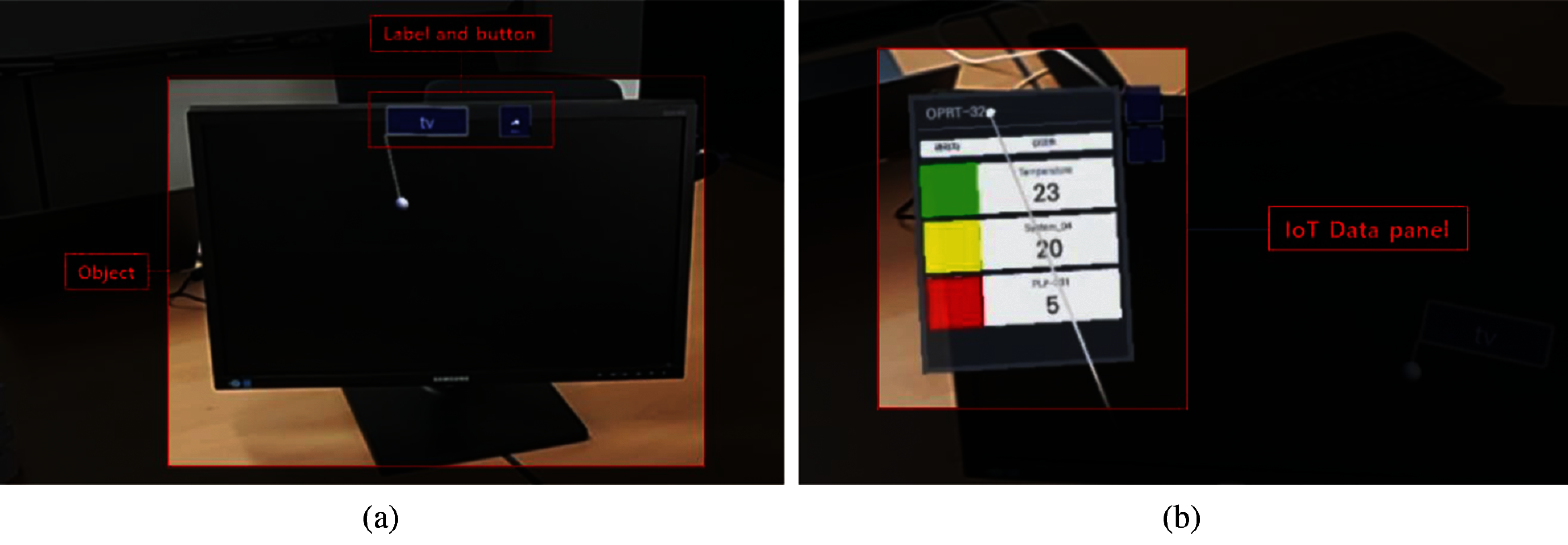
Figure 11: Marker-less M2MR System (a) Faster R-CNN-based OT and UI (b) Demonstration of the IoT panel
5.2 Core Advantages of the Proposed Architecture
We presented the feasibility of M2MR with a verification experiment and a case study. Lastly, we highlight the core advantages by integrating the oneM2M standard with MR.
Convergence with OneM2M to MR: We implemented the oneM2M interface on the Non-oneM2M device, Microsoft HoloLens. OneM2M ensures various quality attributes by providing various CSFs such as interoperability, reusability, and security. In particular, the purpose of the oneM2M standard is to support multiple vendors and domains.
Intuitive user interface: MR is a powerful solution that provides intuition to users by overlaying holographic information in the surrounding physical context. Merging the MR into the IoT environment can help users manage sensors and actuators on-site. IoT devices can be found in MBS or MLS, instead of users searching for them in data tables or maps.
In this paper, we proposed the oneM2M-based convergence platform, called M2MR, to operate AR/MR and IoT systems and services in general-purpose application environments without being subordinate to specific systems, domains, and device manufacturers. The M2MR platform has been implemented utilizing the open-source oneM2M-based IoT server and device platforms and Microsoft HoloLens as an MR device platform. It was validated for three practical cases where IoT and AR/MR are involved together and showed the potential efficacy for future use of AR/MR and IoT integration.
AR/MR provides the capabilities of rich visualizations and interactions on human, tangible objects, locations, and all things. IoT makes the world more innovative by making it possible to monitor and control everything, including various sensors, edge devices, systems, and so on, remotely, autonomously, and in time. The combination of MR and IoT is expected to produce new applications while overcoming each other's limitations. The proposed method enables interoperable data exchanges for applications running on heterogeneous MR devices and IoT elements developed by different vendors in different environments. The M2MR platform we have developed so far is at the prototype implementation of the architecture and primary operations verification. It needs more elaborate structural design and functional supplementation, and we will study the issue further.
Funding Statement: This research was supported by MSIT (Ministry of Science and ICT), Korea, under the ITRC (Information Technology Research Center) support program (IITP-2021-2018-0-01431) and the High-Potential Individuals Global Training Program (2019-0-01611) supervised by the IITP (Institute for Information & Communications Technology Planning & Evaluation).
Conflicts of Interest: The authors declare that they have no conflicts of interest to report regarding the present study.
1. A. Corradi, L. Foschini, C. Giannelli, R. Lazzarini, C. Stefanelli et al., “Smart appliances and RAMI 4.0: Management and servitization of ice cream machines,” IEEE Transactions on Industrial Informatics, vol. 15, no. 2, pp. 1007–1016, 2018. [Google Scholar]
2. W. Kang, S. Moon and J. Park, “An enhanced security framework for home appliances in smart home,” Human-Centric Computing and Information Sciences, vol. 7, no. 6, pp. 1–12, 2017. [Google Scholar]
3. B. Risteska Stojkoska and K. Trivodaliev, “A review of internet of things for smart home: Challenges and solutions,” Journal of Cleaner Production, vol. 140, pp. 1454–1464, 2017. [Google Scholar]
4. B. Chen, J. Wan, L. Shu, P. Li, M. Mukherjee et al., “Smart factory of industry 4.0: Key technologies, application case, and challenges,” IEEE Access, vol. 6, pp. 6505–6519, 2017. [Google Scholar]
5. G. Hwang, J. Lee, J. Park and T. -W. Chang, “Developing performance measurement system for internet of things and smart factory environment,” International Journal of Production Research, vol. 55, pp. 1–13, 2016. [Google Scholar]
6. J. Wan, S. Tang, D. Li, M. Imran, C. Zhang et al., “Reconfigurable smart factory for drug packing in healthcare industry 4.0,” IEEE Transactions on Industrial Informatics, vol. 15, no. 1, pp. 507–516, 2019. [Google Scholar]
7. B. Cheng, G. Solmaz, F. Cirillo, E. Kovacs, K. Terasawa et al., “Fogflow: Easy programming of IoT services over cloud and edges for smart cities,” IEEE Internet of Things Journal, vol. 5, no.2, pp. 696–707, 2018. [Google Scholar]
8. M. Mohammadi, A. Al-Fuqaha, M. Guizani and J. Oh, “Semi-supervised deep reinforcement learning in support of IoT and smart city services,” IEEE Internet of Things Journal, vol. 5, no. 2, pp. 624–635, 2018. [Google Scholar]
9. P. Milgram and F. Kishino, “A taxonomy of mixed reality visual displays,” IEICE Transactions on Information Systems, vol. 77, no. 12, pp. 1321–1329, 1994. [Google Scholar]
10. S. Jabbar, F. Ullah, S. Khalid, M. Khan and K. Han, “Semantic interoperability in heterogeneous IoT infrastructure for healthcare,” Wireless Communications and Mobile Computing, vol. 2017, pp. 1–10, 2017. [Google Scholar]
11. S. Soursos, I. Zarko, P. Zwickl, I. Gojmerac, G. Bianchi et al., “Towards the cross-domain interoperability of IoT platforms,” in European Conf. on Networks and Communications, Athene, Greece, 2016. [Google Scholar]
12. R. Belen, T. Bednarz and D. Favero, “Integrating mixed reality and internet of things as an assistive technology for elderly people living in a smart home,” in 17th Int. Conf. on Virtual-Reality Continuum and Its Applications in Industry, Brisbane, Queensland, Australia, 2019. [Google Scholar]
13. A. Mahroo, L. Greci and M. Sacco, “Holohome: An augmented reality framework to manage the smart home,” in Augmented Reality, Virtual Reality, and Computer Graphics, Santa Maria al Bagno, Italy, 2019. [Google Scholar]
14. H. Pargmann, D. Euhausen and R. Faber, “Intelligent big data processing for wind farm monitoring and analysis based on cloud-technologies and digital twins: A quantitative approach,” in 2018 IEEE 3rd Int. Conf. on Cloud Computing and Big Data Analysis, Chengdu, China, 2018. [Google Scholar]
15. L. Zhang, S. Chen, H. Dong and A. El Saddik, “Visualizing toronto city data with holoLens: Using augmented reality for a city model,” IEEE Consumer Electronics Magazine, vol. 7, no. 3, pp. 73–80, 2018. [Google Scholar]
16. Z. Rashid, J. Melià-Seguí, R. Pous and E. Peig, “Using augmented reality and internet of things to improve accessibility of people with motor disabilities in the context of smart cities,” Future Generation Computer Systems, vol. 76, pp. 248–261, 2017. [Google Scholar]
17. H. Jang, M. Choi, S. Lee, J. Lee and S. Park, “Building energy management system based on mixed reality for intuitive interface,” in IEEE 2nd Int. Conf. on Electronics Technology, Chengdu, China, 2019. [Google Scholar]
18. G. Mylonas, C. Triantafyllis and D. Amaxilatis, “An augmented reality prototype for supporting IoT-based educational activities for energy-efficient school buildings,” Electronic Notes in Theoretical Computer Science, vol. 343, pp. 89–101, 2019. [Google Scholar]
19. D. Jo and G. Kim, “Iot + AR: Pervasive and augmented environments for ‘Digi-log’ shopping experience,” Human-Centric Computing and Information Sciences, vol. 9, no. 1, pp. 1–17, 2019. [Google Scholar]
20. I. Mizutani, M. Kritzler, K. García and F. Michahelles, “Intuitive interaction with semantics using augmented reality: A case study of workforce management in an industrial setting,” in The Seventh Int. Conf. on the Internet of Things, New York, NY, USA, 2017. [Google Scholar]
21. J. Guhl, S. Tung and J. Kruger, “Concept and architecture for programming industrial robots using augmented reality with mobile devices like microsoft holoLens,” in IEEE Int. Conf. on Emerging Technologies and Factory Automation, Limassol, Cyprus, 2017. [Google Scholar]
22. B. Hoppenstedt, M. Schmid, K. Kammerer, J. Scholta, M. Reichert et al., “Analysis of fuel cells utilizing mixed reality and IoT achievements,” in 6th Int. Conf. on Augmented Reality, Virtual Reality and Computer Graphics, Otranto, Italy, 2019. [Google Scholar]
23. E. Stark, E. Kucera, O. Haffner, P. Drahoš and R. Leskovský, “Using augmented reality and internet of things for control and monitoring of mechatronic devices,” Electronics, vol. 9, no. 8, pp. 1–21, 2020. [Google Scholar]
24. T. Park, M. Zhang and Y. Lee, “When mixed reality meets internet of things: Toward the realization of ubiquitous mixed reality,” GetMobile: Mobile Computing and Communications, vol. 21, pp. 10–14, 2018. [Google Scholar]
25. P. Phupattanasilp and S.-R. Tong, “Augmented reality in the integrative internet of things (AR-IoTApplication for precision farming,” Sustainability, vol. 11, no. 9, pp. 1–17, 2019. [Google Scholar]
26. K. Martin and J. Laviola, “The transreality interaction platform: Enabling interaction across physical and virtual reality,” in 2016 IEEE Int. Conf. on Internet of Things and IEEE Green Computing and Communications and IEEE Cyber, Physical and Social Computing and IEEE Smart Data, China, 2016. [Google Scholar]
27. G. Koutitas, J. Jabez, C. Grohman, C. Radhakrishna, V. Siddaraju et al., “Demo/poster abstract: XReality research lab — augmented reality meets internet of things,” in IEEE Conf. on Computer Communications Workshops, Honolulu, HI, USA, 2018. [Google Scholar]
28. A. Croatti and A. Ricci, “A model and platform for building agent-based pervasive mixed reality systems, advances in practical applications of agents,” in Int. Conf. on Practical Applications of Agents and Multi-Agent Systems, Toledo, Spain, 2018. [Google Scholar]
29. Ó. Blanco-Novoa, P. Fraga-Lamas, M. Vilar-Montesinos and T. Fernández-Caramés, “Creating the internet of augmented things: An open-source framework to make IoT devices and augmented and mixed reality systems talk to each other,” Sensors, vol. 20, no. 11, pp. 3328, 2020. [Google Scholar]
30. J. Swetina, G. Lu, P. Jacobs, F. Ennesser and J. Song, “Toward a standardized common M2M service layer platform: Introduction to oneM2M,” IEEE Wireless Communications, vol. 21, pp. 20–26, 2014. [Google Scholar]
31. I. Crnkovic, S. Larsson and M. Chaudron, “Component-based development process and component lifecycle,” in 2006 Int. Conf. on Software Engineering Advances, Tahiti, 2006. [Google Scholar]
32. S. Lee, G. Lee, G. Choi, B. Roh and J. Kang, “Integration of onem2m-based IoT service platform and mixed reality device,” in 2019 IEEE Int. Conf. on Consumer Electronics, Vegas, NV, USA, 2019. [Google Scholar]
33. S. Ren, K. He, R. Girshick and J. Sun, “Faster R-cNN: Towards real-time object detection with region proposal networks,” IEEE Transactions on Pattern Analysis and Machine Intelligence, vol. 39, no. 6, pp. 1137–1149, 2017. [Google Scholar]
 | This work is licensed under a Creative Commons Attribution 4.0 International License, which permits unrestricted use, distribution, and reproduction in any medium, provided the original work is properly cited. |