DOI:10.32604/cmc.2022.020903
| Computers, Materials & Continua DOI:10.32604/cmc.2022.020903 | |
| Article |
A Cost-Efficient Environment Monitoring Robotic Vehicle for Smart Industries
1Suranaree University of Technology, Nakhon Ratchasima, 30000, Thailand
2University of Engineering and Technology, Lahore, Pakistan
3The University of Lahore, Lahore, Pakistan
*Corresponding Author: Chitapong Wechtaisong. Email: chitapong@g.sut.ac.th
Received: 13 June 2021; Accepted: 10 August 2021
Abstract: Environmental monitoring is essential for accessing and avoiding the undesirable situations in industries along with ensuring the safety of workers. Moreover, inspecting and monitoring of environmental parameters by humans lead to various health concerns, which in turn brings to the requirement of monitoring the environment by robotics. In this paper, we have designed and implemented a cost-efficient robotic vehicle for the computation of various environmental parameters such as temperature, radiation, smoke, and pressure with the help of sensors. Furthermore, the robotic vehicle is designed in such a way that it can be dually controlled by using the remote control along with the distant computer. In addition, contrary to the existing researches, the GSM modules are used to achieve the two-way long distance communication between the robotic vehicle and the distant computer. On the distant computer, the above-mentioned environmental parameters can be monitored along with controlling the robotic vehicle with the help of Graphical User Interface (GUI). In order to fulfill the given tasks, we have proposed two algorithms implemented at the robotic vehicle and the distant computer respectively in this paper. The final results validate the proposed algorithms where the above-mentioned environmental parameters can be monitored along with the smooth-running operation of the robotic vehicle.
Keywords: Industry 4.0; sensors; robotic vehicle; distant communication; environment monitoring
Recently, the fourth stage of industrialization, which is also named as Industry 4.0, has emerged as one of the main topics of discussion and research all over the world [1]. Moreover, many researchers have presented various theories to define the concepts of Industry 4.0. Some researchers have defined industry 4.0 based on business point of view [2], digitization, Internet of Things (IoT), and many other interconnected technologies that are deemed to be implemented in Industry 4.0 [3–5]. Actually, IoT is the core component of Industry 4.0 because it provides automation and along with helping to communicate between things based on real-time monitoring though sensors and other technologies [6,7].
Various sensors are used to fulfill the requirements of Internet of Things such as Wireless Sensor Networks (WSN) [8], Quartz Crystal Microbalance (QCM) [9,10], electrochemical sensors [11], metal oxide semiconductor sensors [12]. WSNs are immensely investigated in the literature out of the above-mentioned sensors in terms of their deployment and the integration methodologies [13] because of their significant benefits. In WSNs, sensor nodes are used to sense the environment along with sending the data to the base station (BS) where the main processing is performed [14]. WSNs are widely implemented for various applications such as traffic controlling, digital homes, military, and the disaster management applications. In [15], WSNs are deployed for the monitoring of air pollution such as industrial waste gases and motor vehicle exhaust. In [16], WSNs are utilized for the automatic weather monitoring system to sense the environmental parameters such as humidity, temperature, and the existence of gases. However, there are a lot of disadvantages associated with WSNs such as geographical and energy issues, deployment issues, cost issues and the limited bandwidth.
These drawbacks can be significantly resolved with the help of robotics especially for the environmental monitoring. Actually, the data from the desired location is collected and transferred to the base station or the server with the aim of monitoring the certain environment in environmental monitoring. Environment can be monitored for various applications such as examining volcanoes [17], industrial applications, fire detection applications [18], air quality monitoring [19], with the aim of taking the required steps to overcome the undesired situations [20].
In [21], the authors have wirelessly monitored the temperature, light intensity, gas leakage, humidity and the intensity of rain by using the Arduinno UNO. But the range of sending the data along with receiving the instructions is so limited and the focus of the research is mainly of the data analysis and visualization by using MATLAB. In [22], the authors have designed an autonomous robotic vehicle for area mapping along with the environmental monitoring by using various sensors. However, they are not able to transmit/receive the desired information at a long distance because they used Raspberry Pi 3 in order to have the communication between the robotic vehicle and the computer. In [23], the authors have developed a remotely operated robotic vehicle for the monitoring of water quality based on IoT. In [24], the authors have developed a solar powered robotic vehicle to monitor and manage the unstable networks. In order to achieve the communication between the robotic vehicle and the computer, WiFi is used in that research. In [25], a mobile robotic vehicle is used for the monitoring of plant's volume and health. The mobile robotic vehicle was equipped with different sensors to monitor the volumetric and environmental conditions of the plants. In [26], the authors have designed and implemented a troubleshooting and real-time monitoring system based on LoRaWAN communication. Actually, WiFi allows the coverage of short and medium distances at high data rates, whereas LoRaWAN allows the long-range coverage (5–10 km) at low data rates.
In this paper, we worked on the designing and implementation of a cost-efficient robotic vehicle for the monitoring of environmental parameters such as temperature, radiation, smoke, and the pressure with the help of sensors that are installed on the robotic vehicle. In order to achieve the long-distance communication, we have used the GSM modules that are installed on the robotic vehicle and the distant computer, respectively. Moreover, the robotic vehicle is equipped with a dual-controlled mechanism such as controlling by using the remote control and the distant computer with the help of GSM communication. The Arduino Uno and the Arduino Mega are used to control the operations of the robotic vehicle. Actually, all sensors and the GSM module are connected with the Arduino Uno, and the Arduino Mega controls the motion of the robotic vehicle by using the instructions given from the remote-control device along with the distant computer. Furthermore, we have proposed two algorithms for the smooth-running operation of the robotic vehicle. The experimental results, which can be seen on the distant computer with the help of GUI, validate the proposed algorithm along with the smooth-running operation of the robotic vehicle. The contributions and novelties of this paper are summarized as follows:
• Environmental parameters are computed and monitored by using the cost-efficient robotic vehicle.
• The robotic vehicle is equipped with a dual-controlled mechanism such as controlling by using the remote control and the distant computer with the help of GSM communication.
• Finally, we have proposed two algorithms for the smooth-running operation of the robotic vehicle, and the experimental results validate the proposed algorithm along with the smooth-running operation of the robotic vehicle.
The rest of the paper is organized as follows: The Section 2 contains the designing and implementation of the robotic vehicle, and the working algorithms of the robotic vehicle are discussed in the Section 3. Furthermore, the Section 4 includes the experiment results. Finally, the Section 5 concludes the research work.
2 Designing and the Configuration of the Robotic Vehicle
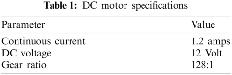
The first step was the selection of motors for the robotic vehicle. We used two 12 V DC gear motors for our robot with the following specifications [Tab. 1]:
The next step was the selection of the robotic base. Actually, there are two types of commonly used robotic bases. The first one is the rectangular shaped base, where four motors are required to operate the robot. However, the issues of using rectangular shaped base is the requirement of having 4 h-bridge circuits along with the more power consumptions, which definitely will be a costly option to opt for. The second one is the round shaped base, where we require only two motors to drive the wheels along with the two freewheeling wheels. In this paper, we opted for the latter one because of our aim of designing a cost-efficient robot. The Fig. 1 unveils the base of the robotic base along with the attachment of motors. As far as the material of the robotic base is concerned, we used backlight sheet because of being less weight. The next step was the designing of motor driving circuits. We used H-bridge IC L298 to drive the motors, and it has four inputs and outputs along with two enable pins as it can be seen in the Fig. 2. We connected one motor between the terminals Output 1 and Output 2 and the second motor between the terminals Output 3 and Output 4. The configuration of motors can be seen in the Fig. 3. The Tab. 2 unveils the logic of controlling the motion of motors, where the status of inputs and outputs can be seen with respect to the motion of both motors.
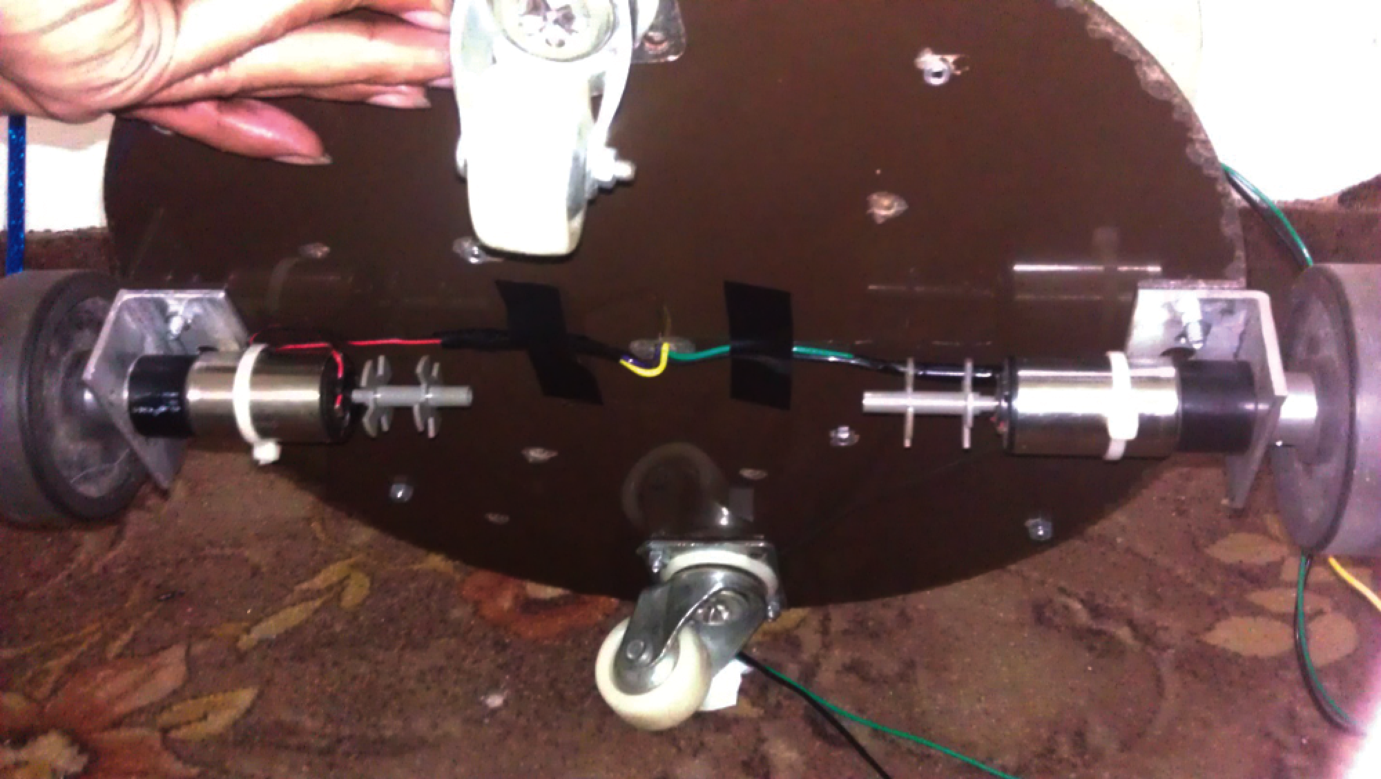
Figure 1: Base of the robotic vehicle
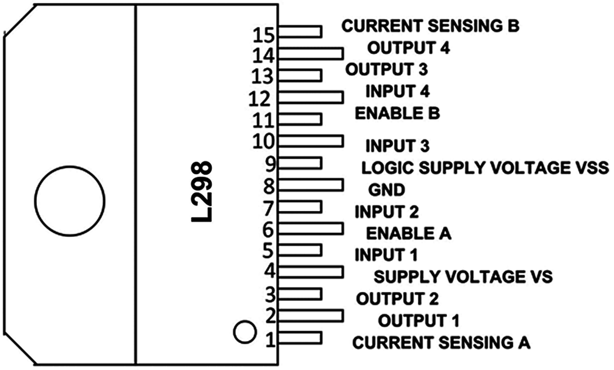
Figure 2: H-Bridge control IC
In order to control the operations of the robotic vehicle, we have used Arduino Uno and Arduino Mega microcontrollers. The Technical specifications of the given microcontrollers can be seen in the Tabs. 3 and 4, respectively.
Moreover, in order to monitor the temperature, smoke, radiation, and the pressure, we have used the LM-35 (temperature sensor), MQ-6 (smoke sensor), GM Tube (radiation sensor), and the pressure sensor (BMP-180). The technical specifications are shown in the Fig. 4. All the sensors are connected with the Arduino Uno. To achieve the two-way communication between the robotic vehicle and the distant computer, we have used GSM modem SIM900 which can perform various tasks similar to normal mobile phones such as text messages, phone calls, TCP/IP, internet connectivity, etc. The pin configuration and the technical configuration of this module can be seen in the Fig. 5.
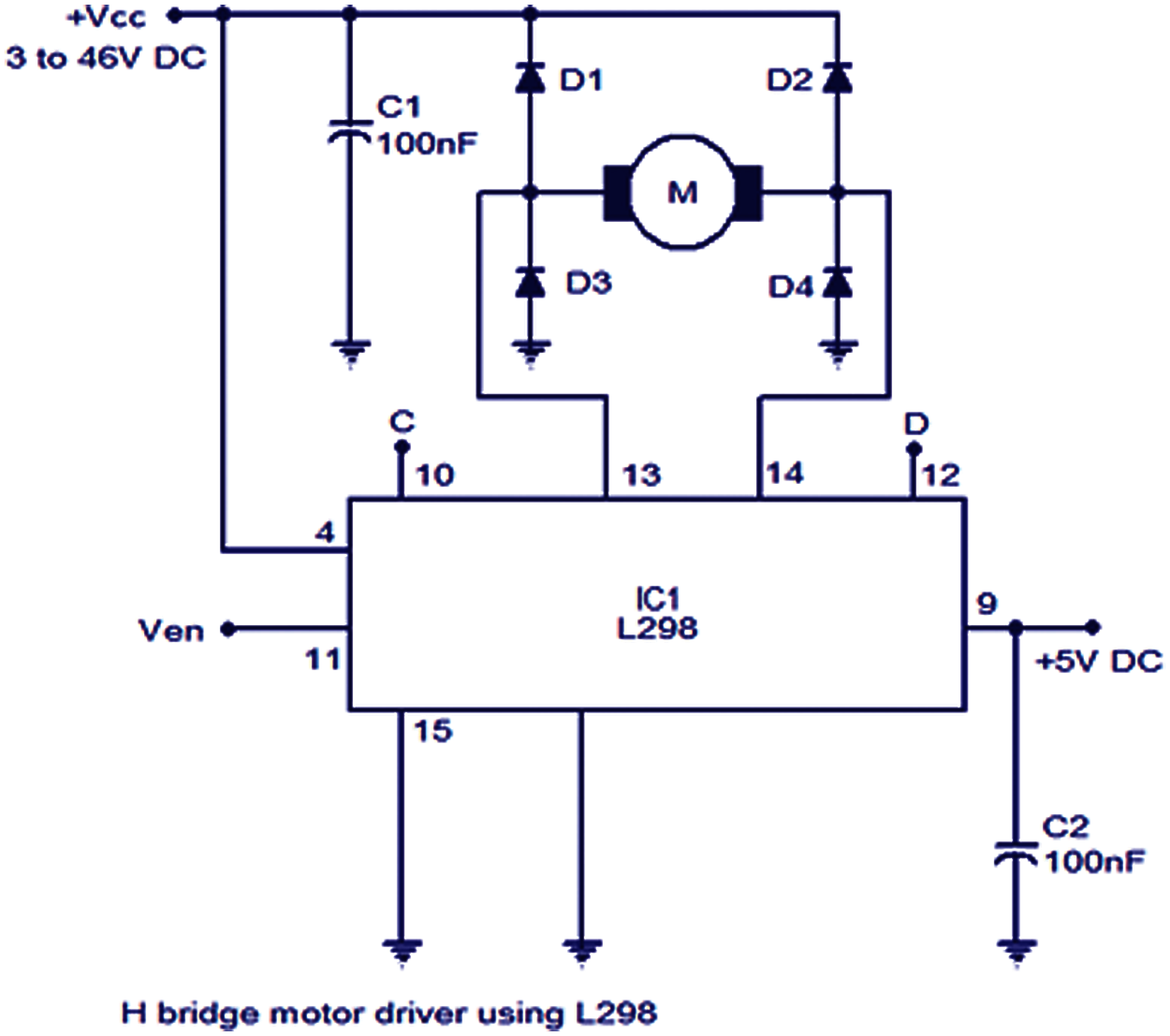
Figure 3: Motor configuration with the drive circuit
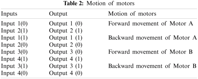
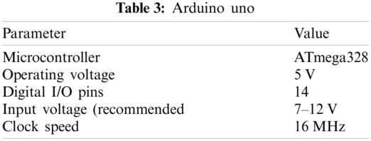
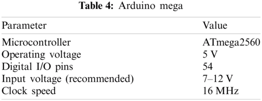
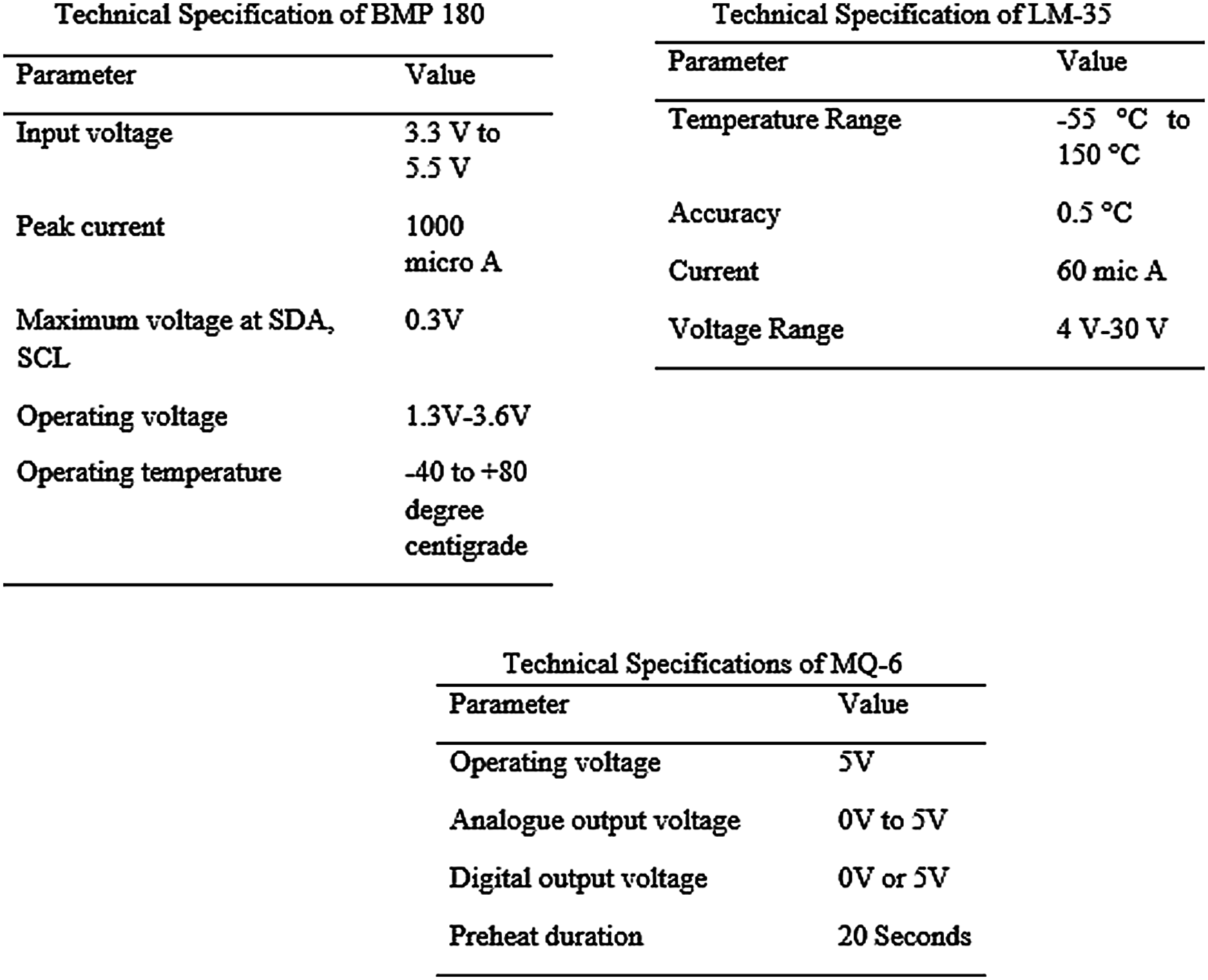
Figure 4: Technical specifications of sensors
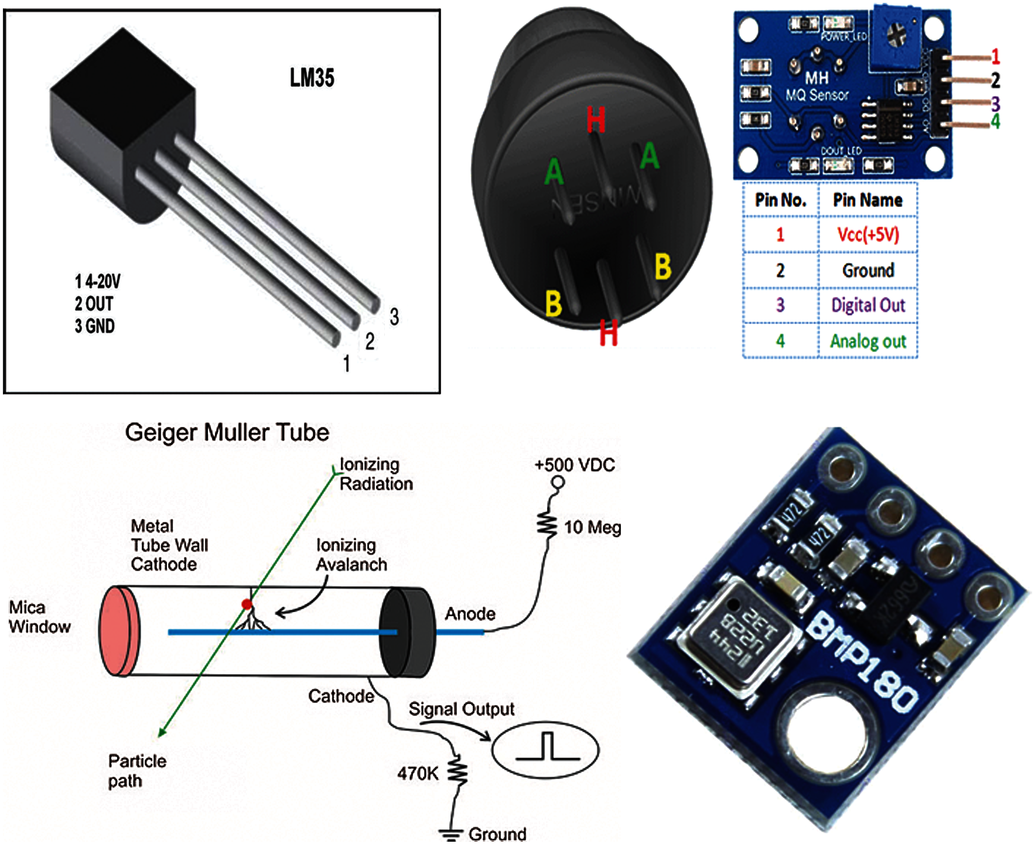
Figure 5: Pin configurations of sensors
Furthermore, as we mentioned above that the robotic vehicle can be controlled remotely as well, we have used the transmitter and receiver. We created another layer on the top of the robotic vehicle where we connected the receiver with the Arduino Mega with the help of optocoplers as can be seen in the Figs. 6 and 7.
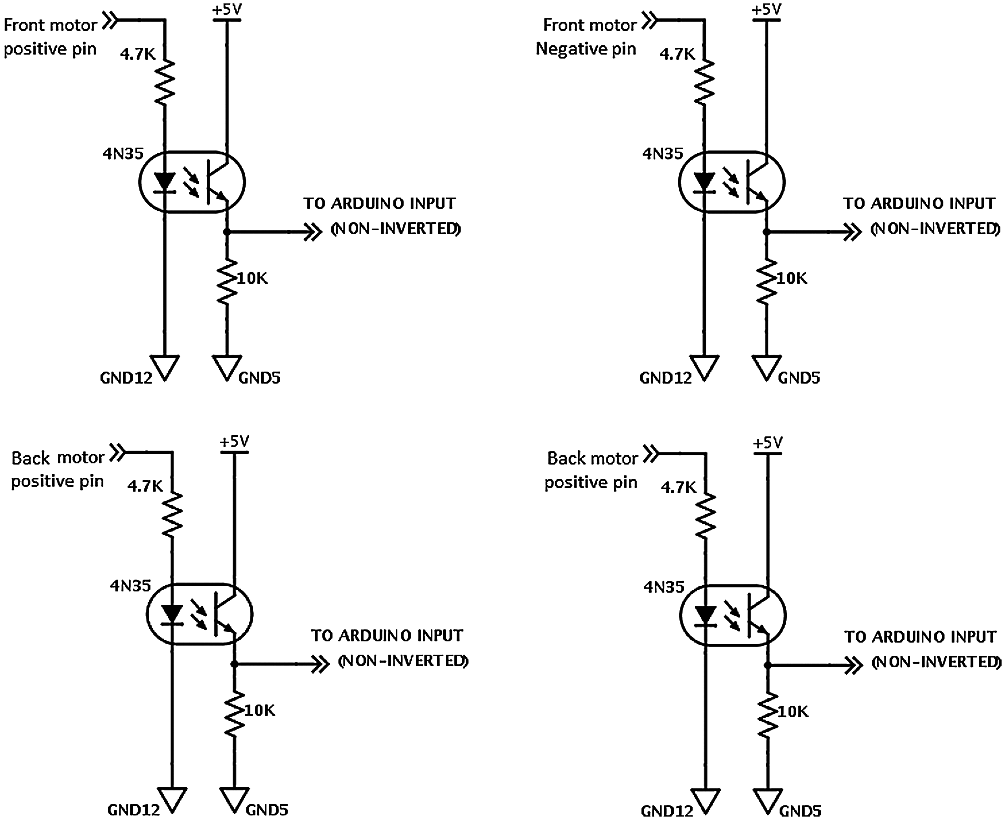
Figure 6: Controlling motor through optocoper circuits
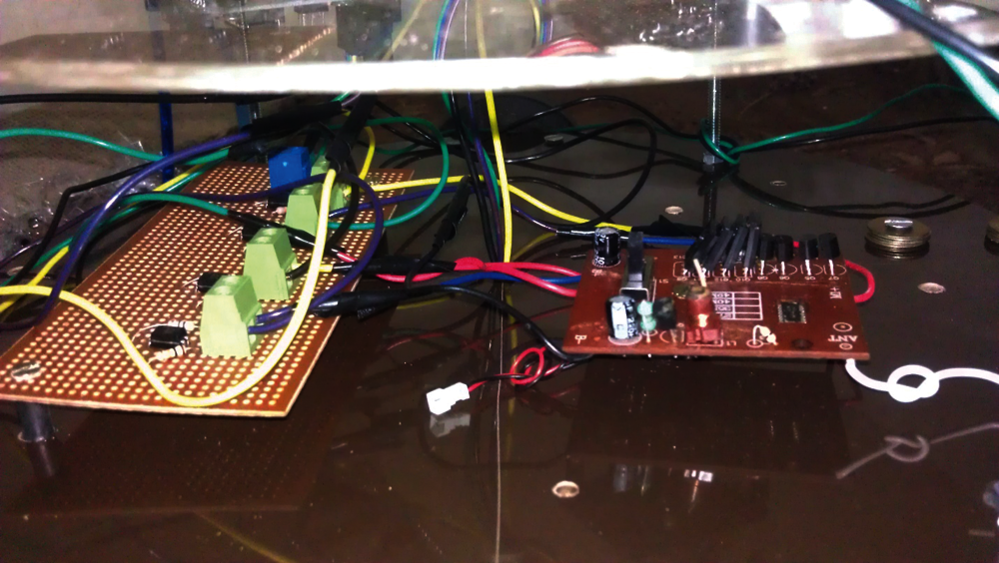
Figure 7: Second layer of the robotic vehicle
As it can be seen in the Fig. 6, outputs of the optocoplers are connected with Arduino Mega. When we press left/right/forward/reserve keys from the remote control, then the respective optocopler responds and the motion of motors can be controlled accordingly with the help of Arduino Mega.
The Fig. 8 unveils the hardware connections of the robotic vehicle where it can be seen that all the sensors are connected with the Arduino Uno along with the GSM module. Following the reception of the desired motion of the robotic vehicle from the distant computer via the GSM module, the Arduino Uno compares the received SMS message with the set format and passes the desired motion message to the Arduino mega. Consequently, the Arduino mega controls the motion of the robotic vehicle. As it can be seen in the Fig. 8, the remote controlling mechanism is also implemented at the Arduino mega. The Fig. 9 unveils the block diagram of the hardware at the distant computer where it can be seen that the GSM module is connected in order to send/receive the messages with the help of Arduino Uno. The robotic vehicle with all the connected hardware can be seen in the Fig. 10.
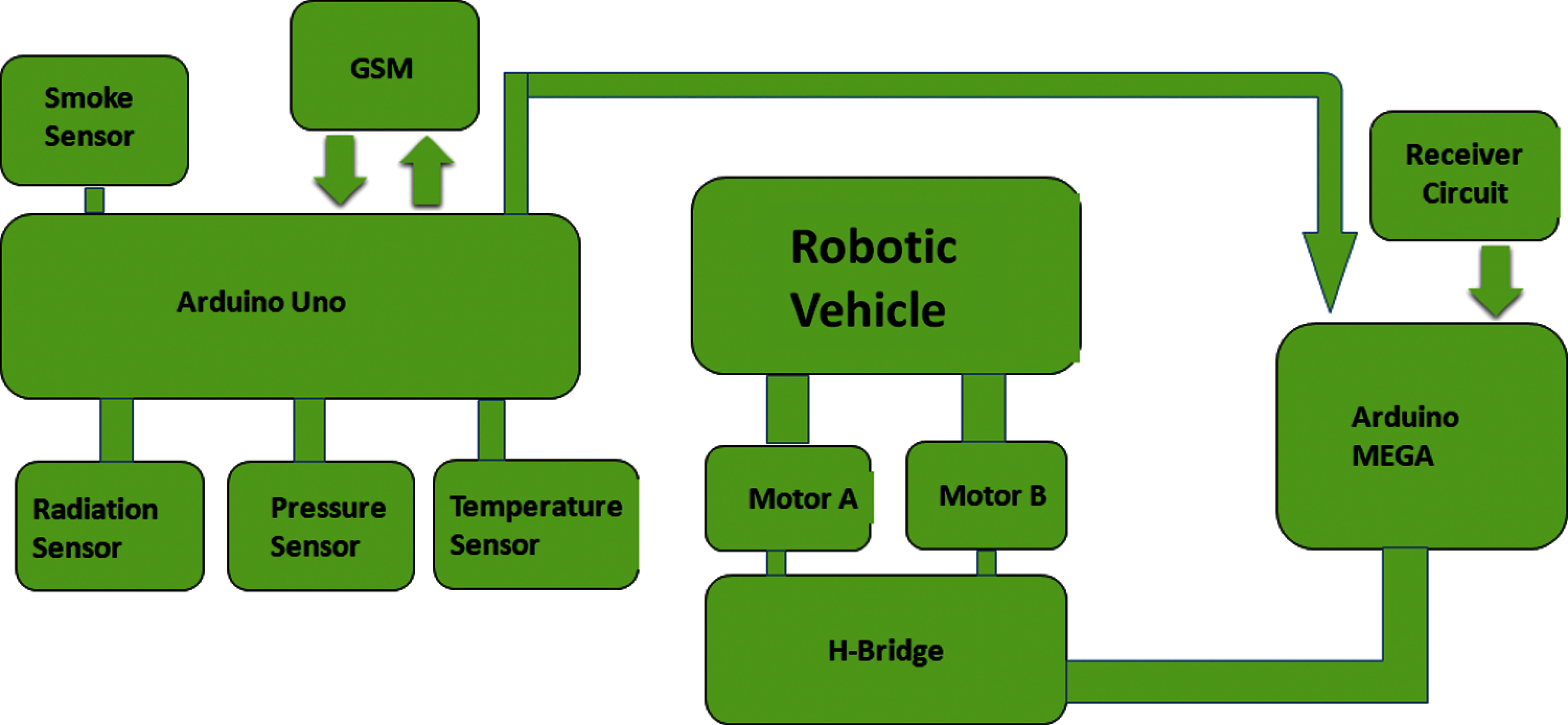
Figure 8: Block diagram of the hardware connections at the robotic vehicle
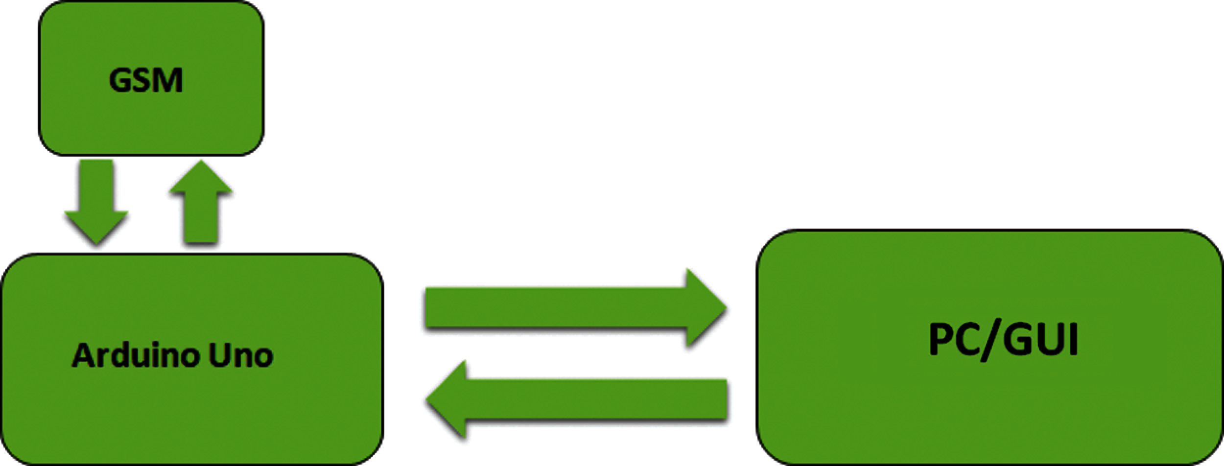
Figure 9: Block diagram of the hardware connections at the distant computer
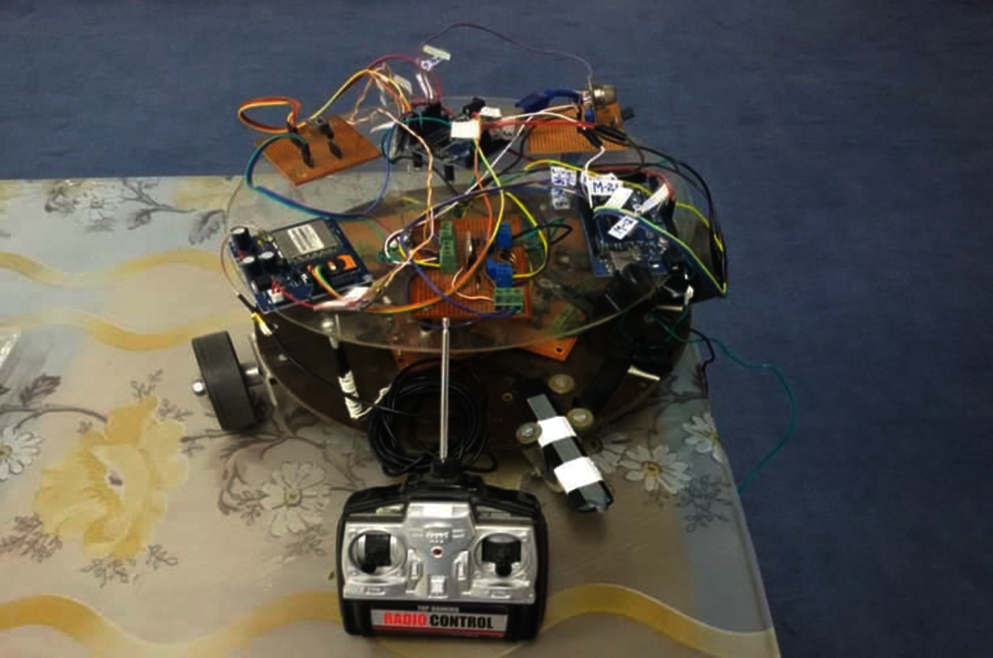
Figure 10: Robotic vehicle
In this section, we have discussed the proposed working algorithms implemented at the robotic vehicle and the distant computer, respectively. The first step is the initialization of GSM module and the environment monitoring sensors. Following the initialization of sensor, we have to set time to send the environmental parameters. If the time has not set, then the system will check that whether the GSM has received the command or not. If the command has received, then the motion of the robotic vehicle will be controlled accordingly as can be seen in the Fig. 11. Furthermore, if the time to send the environmental parameters has set, then the robotic vehicle will read environmental parameters along with sending the values from the vehicle GSM to the GSM installed at the distant computer accordingly.
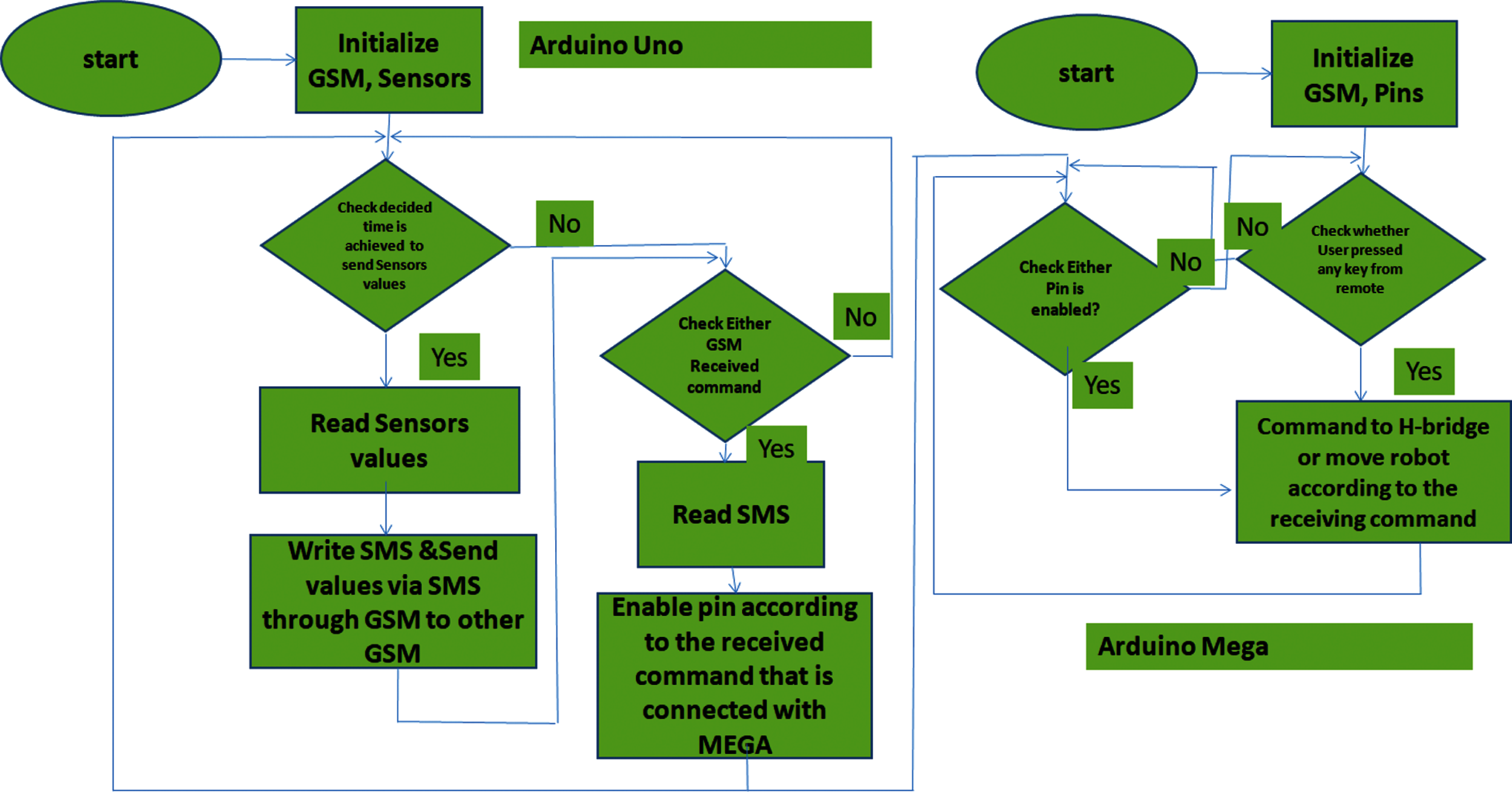
Figure 11: Robotic vehicle controlling algorithm
At the distant computer, we have to initialize the GSM module as can be seen in the Fig. 12. Following the initialization of GSM module, we check that whether the system has received the desired senor values or not. If the environmental values have received, then the system will read the desired parameters and plot the graphs accordingly. Moreover, if the environmental parameters have not received, then the system checks that whether the user has pressed any key to control the motion of robot or not. If the user has initiated any motion, then the required motion message will be send to the GSM installed at the vehicle accordingly.
4 Experimental Results and Discussions
In this section, we have presented and discussed the experimental results. The experimental results are shown by using the GUI on the distant computer with the help of line graphs. The values of temperature, pressure, radiation and the smoke detector are shown on the GUI. Moreover, the motion controlling mechanism of the robotics vehicle is also shown on the bottom right corner of the GUI. The values of temperature, radiation, pressure, range from 0 to 40 C, 0 to 40 hPa, 0 to 2000 counts per second, respectively. The output of the smoke sensor is labeled as “Smoke Detected”, “No Smoke Detected” on the GCU.
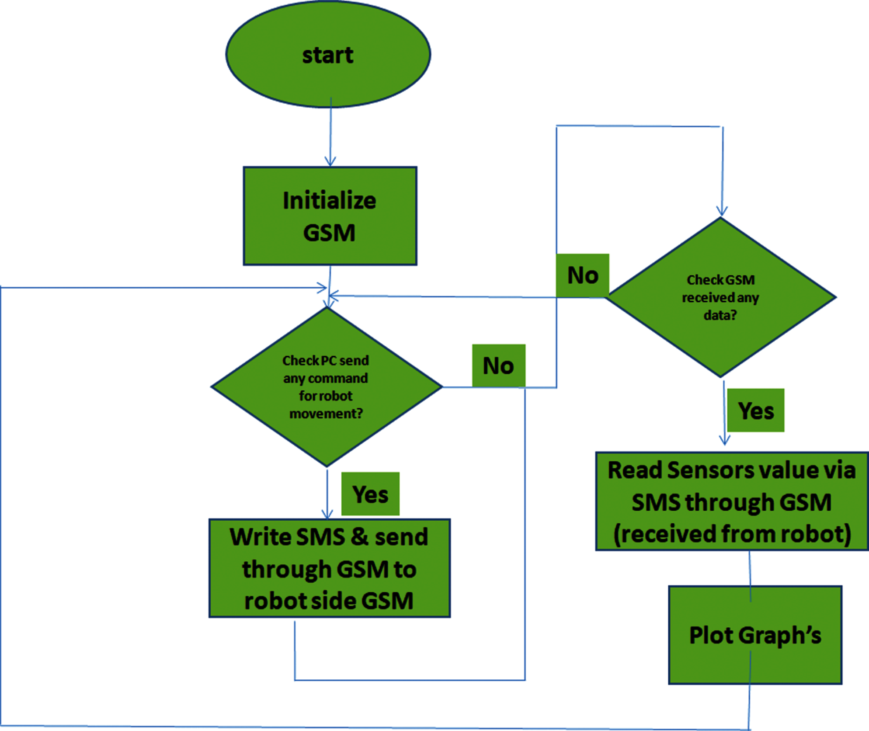
Figure 12: Proposed controlling algorithm at the distant computer
The Fig. 13 unveils the line graphs where the values of temperature, pressure, radiation and smoke sent by the robotic vehicle located on the under-consideration site can be seen. As the under-consideration site has no smoke/fire, the GCU displays “No Smoke Detected”. The radiation detector shows 1100 counts per second.
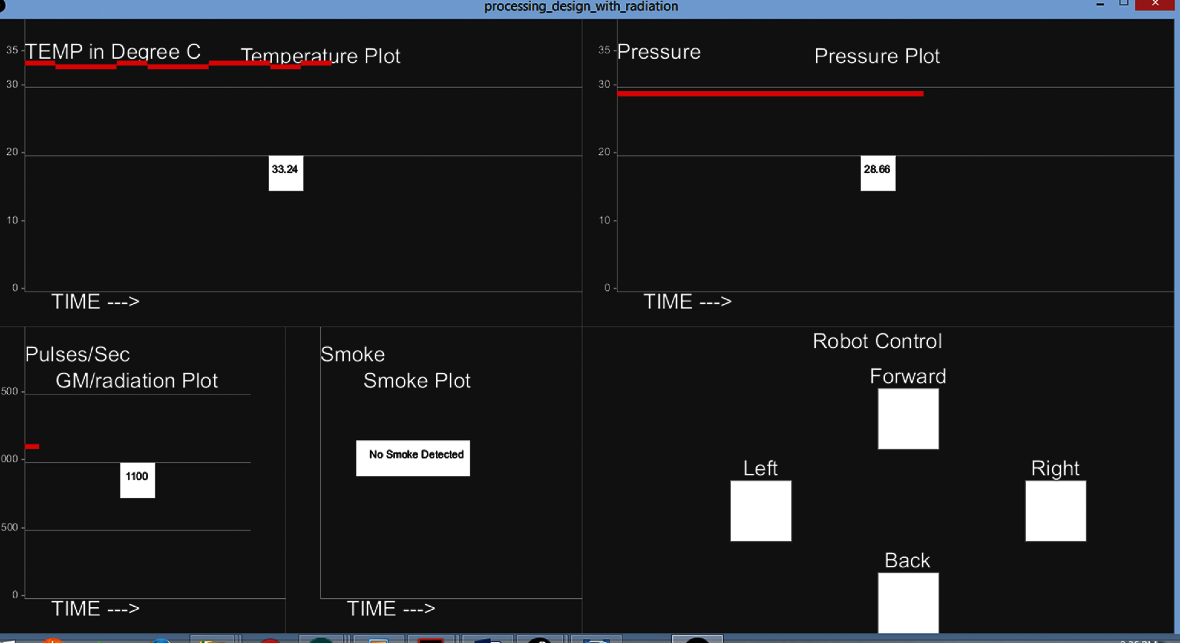
Figure 13: GUI with no smoke detected
The Fig. 14 shows the environmental parameters sensed by the robotic vehicle located at the different site compared to the Fig. 13, where it can be seen that the radiation comes out to be 50 counts per second. In order to check the performance of the smoke detector, we used a cigarette lighter near to the robotic vehicle and the distant computer successfully displays the message “Smoke Detected” on the GCU as it can be seen in the Fig. 15. It is worth mentioning that the data was collected on three consecutive days. The Fig. 13 shows the collected data on the first day, whereas the other figures (Figs. 14 and 15) unveil the collected data on the next two days respectively. All the line plots are based on real time processing with a time interval of 30 s, and the validity of the collected data is dependent on the environment of under-consideration sites.
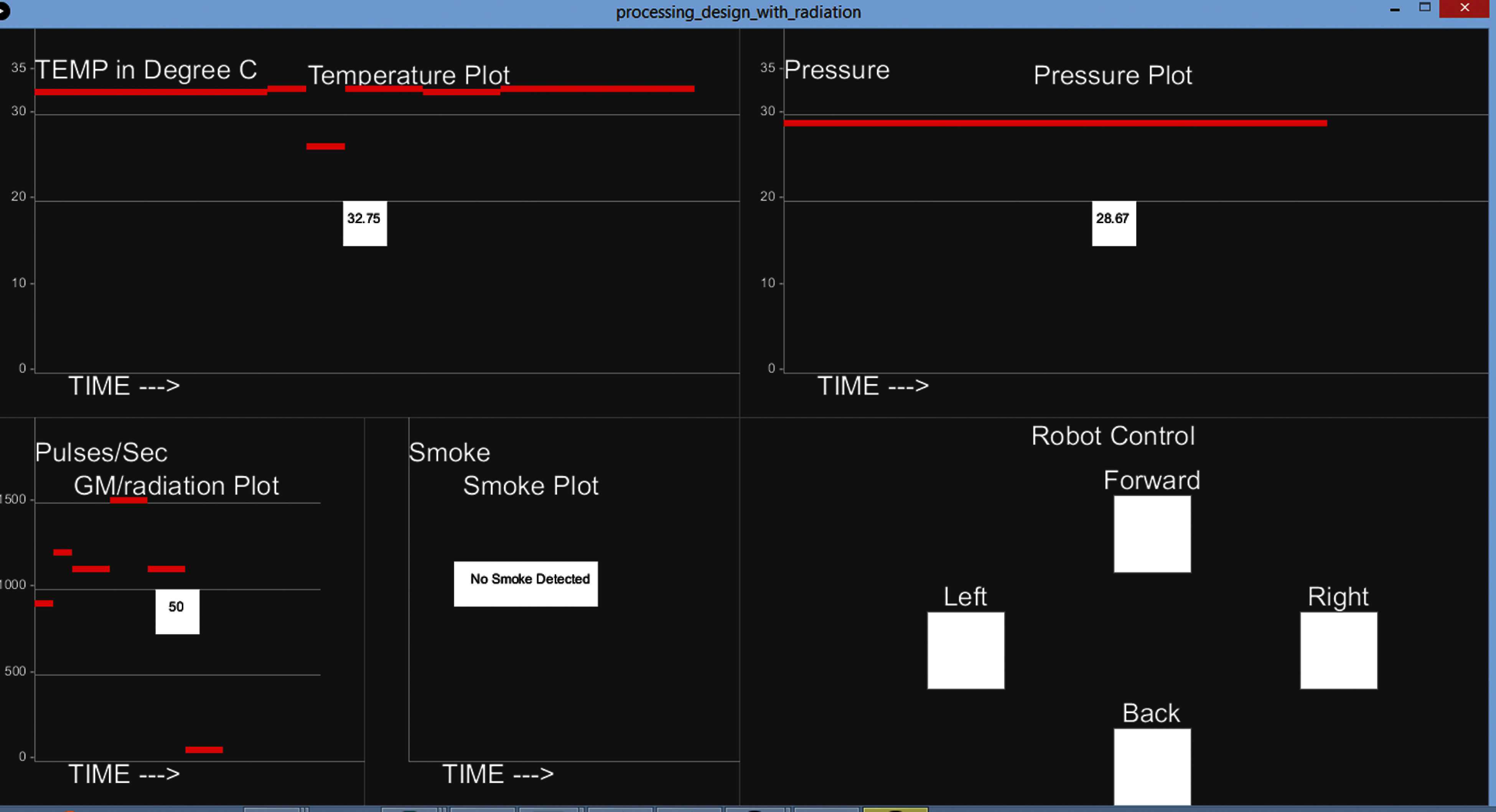
Figure 14: GUI with different environmental values
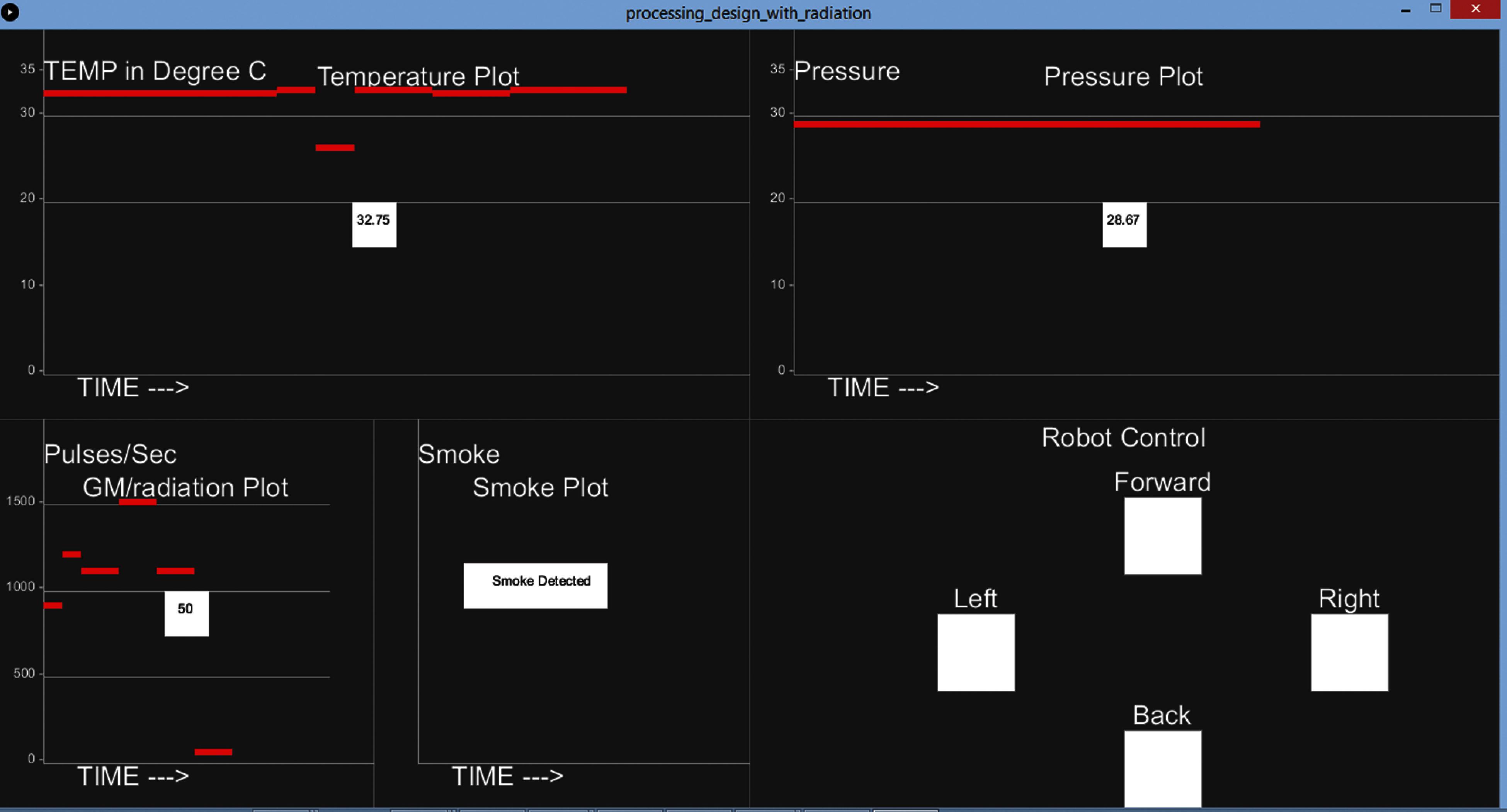
Figure 15: GUI with the smoke detected
In this paper, we worked on the designing and implementation of cost-efficient robotic vehicle for the environment monitoring applications in industries. Actually, the main aim of this research was to create a robotic vehicle in order to ensure the safety of health workers in industries as inspecting and monitoring of environmental parameters in industries could possibly lead to severe health issues. The values of temperature, radiation, pressure, and smoke were computed with the help of sensors that were installed on the robotic vehicle. The robotic vehicle was equipped with two way controlling mechanism, i.e., remote control and the distant computer. Contrary to the existing researchers where the communication between the robotic vehicle and the user was limited to short distances, we used the GSM modules with the aim of achieving a long-distanced communication. In addition, the proposed algorithms worked perfectly and the experimental results could be seen with the help of GUI on the distant computer. The real time values of the temperature, smoke, pressure, radiation along with the controlling mechanism could be seen on the GUI.
Funding Statement: This research was supported by Suranaree University of Technology, Thailand.
Conflicts of Interest: The authors declare that they have no conflicts of interest to report regarding the present study.
1. B. Bajic, A. Rikalovic, N. Suzic and V. Piuri, “Industry 4.0 implementation challenges and opportunities: A managerial perspective,” IEEE Systems Jounal, vol. 15, no. 1, pp. 546–559, 2021. [Google Scholar]
2. M. Piccarozzi, B. Aquilani and C. Gatti, “Industry 4.0 in management studies: A systematic literature review,” Sustainability, vol. 10, no. 10, pp. 1–24, 2018. [Google Scholar]
3. S. S. Kamble, A. Gunasekaran and S. A. Gawankar, “Sustainable industry 4.0 framework: A systematic literature review identifying the current trends and future perspectives,” Process Safety and Environment Protection, vol. 117, pp. 408–425, 2018. [Google Scholar]
4. M. Ghobakhloo, “The future of manufacturing industry: A strategic roadmap,” Journal of Manufuring Technology Management, vol. 29, no. 6, pp. 910–936, 2018. [Google Scholar]
5. D. Preuveneers, “The intelligent industry of the future: A survey on emerging trends, research challenges and opportunities in industry 4.0,” Journal of Ambient Intelligence and Smart Environment, vol. 9, no. 3, pp. 287–298, 2017. [Google Scholar]
6. L. Atzori, A. Iera and G. Morabito, “The internet of things: A survey,” Computer Networks, vol. 54, no. 15, pp. 2787–2805, 2010. [Google Scholar]
7. Y. Chen, H. Chen, A. Gorkhali, Y. Lu, Y. Ma et al., “Big data analytics and big data science: A survey,” Journal of Management Analytics, vol. 3, no. 1, pp. 1–42, 2016. [Google Scholar]
8. I. P. Guembe, P. L. Iturri, J. J. Astrain, E. Aguirre and L. Azpilicueta, “Basketball player on-body biophysical and environmental parameter monitoring based on wireless sensor network integration,” IEEE Access, vol. 9, pp. 27051–27066, 2021. [Google Scholar]
9. W. Pan, X. Huang and Q. Chen, “Uniformization of mass sensitivity distribution of silver electrode QCM,” IEEE Transactions on Ultrasonics, Ferroelectrics, and Frequency Control, vol. 67, no. 9, pp. 1953–1956, 2020. [Google Scholar]
10. M. Rivai, A. Arifin and E. I. Agustin, “Mixed vapour identification using partition column-QCMs and artificial neural network,” in Proc. of Int. Conf. on Information and Communication Technology and Systems, USA, pp. 172–177, 2016. [Google Scholar]
11. Z. Zulkarnain, S. Suprapto, T. Ersam and F. Kurniawan, “A novel selective and sensitive electrochemical sensor for insulin detection,” Indonesian Journal of Electrical Engineering and Computer Science, vol. 3, no. 3, pp. 496–502, 2016. [Google Scholar]
12. S. K. Sinha, “Growth and ammonia sensing properties of Zn1-xSnxO nanofibers,” Sensors Actuators B: Chemical, vol. 219, pp. 192–198, 2015. [Google Scholar]
13. S. J. Ramson and D. J. Moni, “Applications of wireless sensor networks—A survey,” in Proc. of ICEEIMT, Coimbatore, India, pp. 325–329, 2017. [Google Scholar]
14. W. Guo, C. Yan and T. Lu, “Optimizing the lifetime of software defined wireless sensor network via reinforcement learning based routing,” International Journal of Distributed Sensor Networks, vol. 15, no. 2, 2019. [Google Scholar]
15. M. U. Younis, M. K. Khan, M. R. Anjum, S. Afridi, Z. A. Arain et al., “Optimizing the lifetime of software defined wireless sensor network via reinforcement learning.” IEEE Access, vol. 9, pp. 259–272, 2020. [Google Scholar]
16. J. Mabrouki, M. Azrour, D. Dhiba, Y. Farhaoui, S. E. Hajjaji et al., “Iot-based data logger for weather monitoring using arduino-based wireless sensor networks with remote graphical application and alerts,” Big Data Mining and Analytics, vol. 4, no. 1, pp. 25–32, 2021. [Google Scholar]
17. W. Allen, G. Lorincz, K. Johnson, J. Lees and M. Welsh, “Fidelity and yield in a volcano monitoring sensor network.” in Proc. of the 7th Symp. on Operating Systems Design and Implementation, USENIX Association, CA, USA. pp. 381–396, 2006. [Google Scholar]
18. J. Lloret, M. Garcia, D. Bri and S. Sendra, “A wireless sensor network deployment for rural and forest fire detection and verification.” Sensors, vol. 9, no. 11, pp. 8722–8747, 2009. [Google Scholar]
19. S. C. Chang and C. T. Lee, “Secondary aerosol formation through photochemical reactions estimated by using air quality monitoring data in Taipei city from 1994 to 2003.” Atmospheric Environment, vol. 41, no. 19, pp. 4002–4017, 2007. [Google Scholar]
20. H. B. Glasgow, J. M. Burkholder, R. E. Reed, A. J. Lewitus and J. E. Kleinman, “Real-time remote monitoring of water quality: A review of current applications, and advancements in sensor, telemetry, and computing technologies,” Journal of Experimental Marine Biology and Ecology, vol. 300, no. 1, pp. 409–448, 2004. [Google Scholar]
21. B. Jiang and C. F. Huacón, “Cloud-based smart device for environment monitoring,” in 2017 IEEE Conf. on Technologies for Sustainability (SusTechPhoenix, AZ, pp. 1–6, 2017. [Google Scholar]
22. M. Papoutsidakis, K. Kalovrektis, C. Drosos and G. Stamoulis, “Design of an autonomous robotic vehicle for area mapping and remote monitoring,” International Journal of Computer Applications, vol. 167, no. 12, pp. 36–41, 2017. [Google Scholar]
23. M. Adhipramana, R. Mardiati and E. Mulyana, “Remotely operated vehicle (ROV) robot for monitoring quality of water based on IoT,” in Proc. ICWT, Indonesia, 2020. [Google Scholar]
24. B. P. Gautam, K. Wasaki and N. Sharma, “Using a solar powered robotic vehicle to monitor and manage unstable networks,” International Journal of Future Computer and Communication, vol. 3, no. 6, pp. 415–420, 2014. [Google Scholar]
25. M. Bietresato, G. Carabin, D. Dauria, R. Gallo, G. Ristorto et al., “A tracked mobile robotic lab for monitoring the plants volume and health,” in 12th IEEE/ASME Int. Conf. on Mechatronic and Embedded Systems and Applications (MESAAuckland, New Zealand, pp. 1–6, 2016. [Google Scholar]
26. J. Lentz, S. Hill, B. Schott, M. Bal and R. Abrishambaf, “Industrial monitoring and troubleshooting based on LoRa communication technology,” in Proc. Conf. IEEE Ind. Electron. Soc., Washington, DC, USA, pp. 3852–3857, 2018. [Google Scholar]
 | This work is licensed under a Creative Commons Attribution 4.0 International License, which permits unrestricted use, distribution, and reproduction in any medium, provided the original work is properly cited. |