DOI:10.32604/cmc.2022.021244
| Computers, Materials & Continua DOI:10.32604/cmc.2022.021244 | |
| Article |
Left-Handed Characteristics Tunable C-Shaped Varactor Loaded Textile Metamaterial for Microwave Applications
1Space Science Centre, Climate Change Institute, Universiti Kebangsaan Malaysia, Bangi, 43600, Malaysia
2Department of Electrical, Electronic and Systems Engineering, Faculty of Engineering and Built Environment, Universiti Kebangsaan Malaysia, UKM, Bangi, 43600, Selangor, Malaysia
3Advanced Communication Engineering (ACE), Centre of Excellence, Universiti Malaysia Perlis (UniMAP), Perlis, Malaysia
4Faculty of Electronic Engineering Technology, Universiti Malaysia Perlis (UniMAP), Perlis, Malaysia
*Corresponding Author: Mohammad Tariqul Islam. Email: tariqul@ukm.edu.my
Received: 28 June 2021; Accepted: 07 August 2021
Abstract: This paper presents a textile-based C-shaped split-ring resonators (SRR) metamaterial (MTM) unit cells with an electrical tunability function. The proposed MTM was composed of two symmetrical C-shaped SRR combined with a central diagonal metal bar, whereas the RF varactor diode is placed on the backside of the splitted ground plane. Stopband behavior of single and array MTM unit cells were analyzed while the achieved negative index physical characteristics were widely studies. Though four different MTM arrays (i.e., 1 × 1, 1 × 2, 2 × 1, and 2 × 2) were analyzed in simulation, a 2 × 2-unit cell array was chosen to fabricate, and it was further undergone experimental validation. This proposed tunable MTM exhibits double negative (DNG)/left-handed properties with an average bandwidth of more than 2.8 GHz. Furthermore, attainable negative permittivity and negative permeability are within 2.66 to 9.59 GHz and within 2.77 to 15 GHz, respectively, at the frequency of interest (between 1 and 15 GHz). Moreover, the proposed tunable MTM also showed tunable transmission coefficient characteristics. The proposed electrically tunable textile MTM might function in a dynamic mode, making it suitable for a variety of microwave-wearable applications. A satisfactory agreement between simulations and experiments were achieved, demonstrating that the proposed MTM can operate over a wide bandwidth.
Keywords: Textile metamaterial; metamaterial; wearable antennas; tunable metamaterials; metasurface; antennas; DNG metamaterials
The use of microwave wearable prototypes of wireless network communication systems for health monitoring applications have received a lot of attention. In the presence of the human body, smart devices’ design becomes more complicated than a free-space environment due to the enormous losses produced from humans when the prototype is located close to the body [1]. For instance, advancement in wearable devices have demonstrated that conductive wires can be integrated into the skin or clothing. Metamaterial (MTM) techniques have shown that the devices’ electromagnetic (EM) wave can be enhanced by designing a conductive flexible surfaces structure [2].
MTMs with unique properties such as a zero-refractive index [3] and a negative-refractive index [4] are generally used to enhance the overall performance of such a wearable prototype design. Researchers have utilized MTMs in many applications, for instance, invisibility cloaking [5,6], wireless health monitoring [7], sensors [8], filters [9], RFID tags [10], and EM wave absorbers [11]. Besides, MTM structures are being used to control and improve the textile antennas performance, radar, and other microwave or millimeter-wave applications [3,11]. The MTMs are classified as single or double negative (SNG/DNG) based on the behavior of the dielectric permittivity (ɛ) or magnetic permeability (μ). The SNG MTM with negative μ is known as mu-negative (MNG) MTM, whereas SNG MTM with negative ɛ is labeled as the epsilon negative (ENG) MTM [12,13]. However, MTM defines as a DNG/left-handed (LH) MTM when both ɛ and μ are negative [14]. Besides, double-positive (DPS) MTM has both ɛ and μ as positive, commonly found in nature [15]. Several kinds of MTM structures have been reported in the state of the art literature, e.g., split-ring resonators (SRRs) [16], complementary split-ring resonators (CSRR) [17], artificial magnetic conductor (AMC) [18] and symmetric split-ring resonator (SSRR) which can be used to enhance the antenna radiation patterns and to build a more miniaturized size [19].
The wearable applications are mainly used as a supportive and natural layer substitute. Therefore, an electronic function can be integrated with fabrics attributable to miniaturize the electronic components and develop the emerging technologies [20,21]. These kinds of textile fabrics developments have been extensively highlighted in literature with different techniques such as woven fabrics, embroidered fabric material, sewn textile materials, knitted fabrics, chemically treated fabrics, and laminated fabrics [22]. Furthermore, smart sensor devices have been improved recently to be sufficient for the human body [23]. However, the creation process for new textile-based sensors is an enormous task, especially in health tracking [24], athletic training [25], and emergency rescue for law enforcement [26]. Limited research has addressed textile MTMs. For example, a flexible FR4 based CSRR MNG MTM has reported in [27]. It has displayed a negative index characteristic in the range of 7.2–9.2 GHz. However, the MTM is not suitable for wearable applications due to the FR4 substrate, which is not considered for textile/wearable applications. Another research reported textile material work [28] has not achieved an MTM negative index. Moreover, in the design of reconfigurable/tunable MTM-enhanced devices, the manufacturing complexity caused by additional DC biasing must be taken into consideration early in the design process [29].
Besides that, material characteristics can be controlled using different approaches, such as an electrical varactors method, which is popular in beam steering applications compared with the costly phase-shifter devices [30]. For instance, in [31], a varactor diode has presented with a lack of DC biasing data. The applied reverse bias voltage of the varactor can be controlled using an external voltage source. This tuning technique extensively provides a tunable functionality, e.g., tunable metasurfaces development, hence it is considering in the development of many wireless devices [32–34]. Moreover, a tunable MTMs in [35] has applied with an absorption level based on the applied reverse bias voltage.
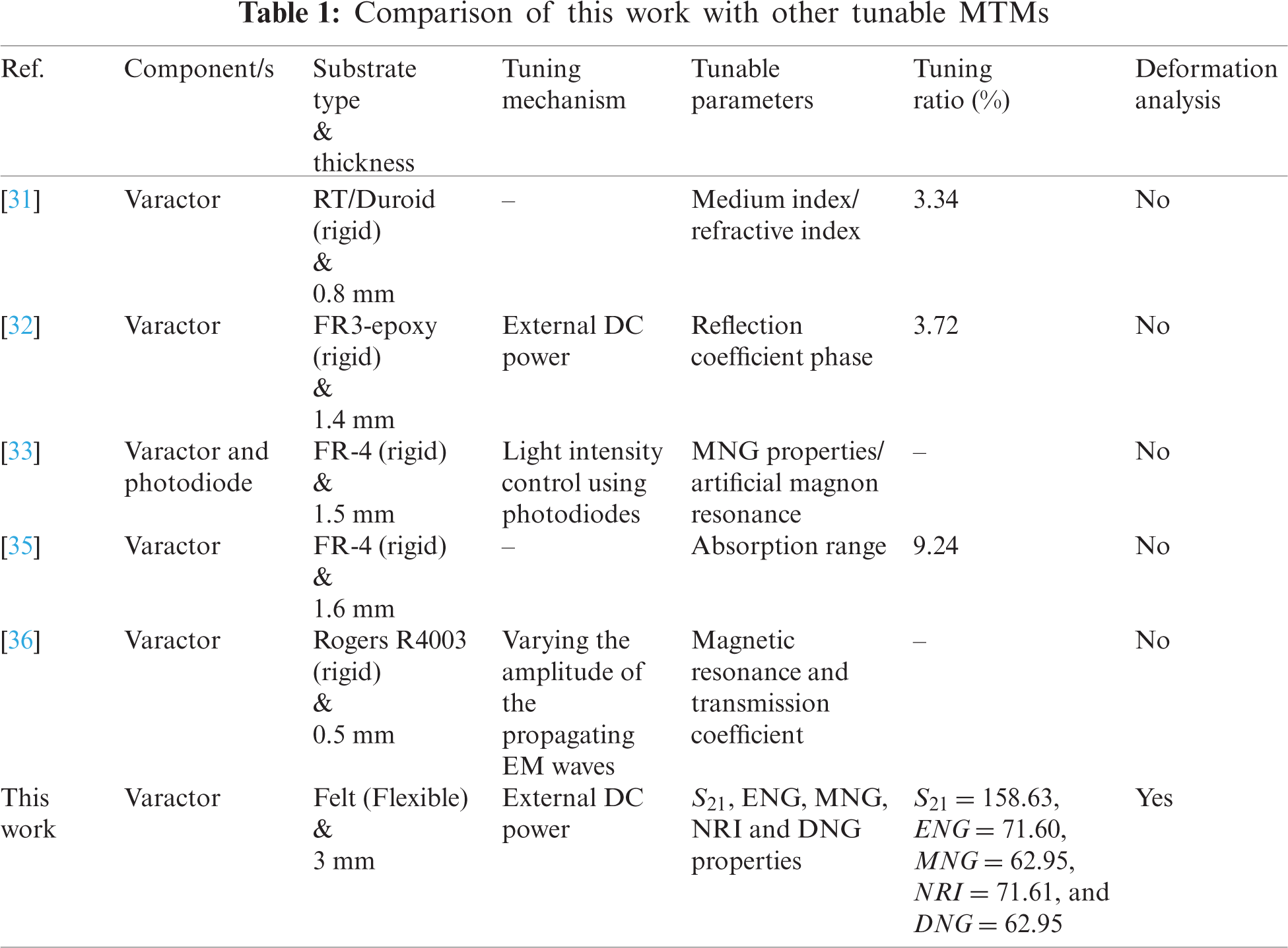
This paper proposes a flexible, multiparameter electrically tunable LH textile MTM. The design was based on several C-shaped split-ring resonators, whereas a slotted ground plane with loaded varactors helped achieve the tunability features. The MTM effective parameters (i.e., ɛ, and μ) were extracted using the robust reflection-transmission (RTR) method for simulated and measured structures. The 2 × 2 array structure was opted to use the waveguide (WG) port measurement approach between 1 and 15 GHz to experimentally validate. The tunable LH features observed varied from 2.89 to 5.42 GHz for both simulation and measurement. Furthermore, simulations exhibited ENG characteristics at 2.66–5.65 GHz, 8.24–8.62 GHz, and 9.11–9.59 GHz; MNG characteristics at 2.77–5.42 GHz, 9.87–12.05 GHz, 12.97–13.39 GHz, 13.81–14.39 GHz, and 14.72–15 GHz; and negative refractive index (NRI) characteristics within 2.73–5.55 GHz. Also, measurements revealed ENG characteristics at 2.89–6.75 GHz and 9.91–11.18 GHz; MNG characteristics at 2.44–6.62 GHz and 10.56–13.79 GHz; and NRI characteristics within 2.61 GHz–5.72 GHz. Tab. 1 displays the research results compared to other tunable/reconfigurable MTMs found in the literature, showing how distinct and versatile the proposed MTM models are, with multiparameter tuning capabilities.
2 Design and Methodology of Tunable MTM Unit Cell
The proposed textile based MTM was developed, simulated, and fabricated using LessEMF Inc.’s ShieldIt SuperTM conductive textile with felt acting as the substrate. For felt, the loss tangent is 0.044, and the dielectric constant is 1.44. And the Shield It is 0.17 mm thick with a conductivity of 1.18
Several pairs of symmetric C-shaped SRRs were designed and combined to structure the MTM unit cell and enable the unit cell to operate in a wide frequency range. Figs. 1a and 1b illustrate the proposed MTM unit cell design by combining several C-shaped SRR resonators and a slotted ground plane loaded with RF varactor diodes (SMV1232-079LF, Skyworks, Irvine, CA, USA). The varactor’s capacitance was tuned based on the applied reverse bias voltages [37]. The size of the MTM unit cell is 15

Figure 1: MTM unit cell. (a) front view and (b) 3D rear view with RF varactor

The entire design procedures of the MTM structure, including considering a slot at the ground plane to insert the RF varactor is presented in Fig. 2. The first step was to create two C-shaped SRRs with 0.8 mm gap, as demonstrated in Fig. 2a. Inner ring conductor was connected using a diagonal metal strip in Fig. 2b, where it was splitted into two sections as shown in Fig. 2c. Furthermore, a slot in the MTM ground plane was considered in Fig. 2c as well. Finally, RF varactor was installed in the ground plane of the MTM to complete the design as illustrated in Fig. 2d. The fabric materials were adopted in this study are flexible. Moreover, DC biasing circuitry was required for tuning the material properties. This research also observed the impact of C-shaped SRRs on the design process to help alleviate issue with the fabrication complexity. Another fact that strongly supports the usage of an SRR type structure is that this has been found to improve the magnetic resonance of the material [38].

Figure 2: Design steps of the MTM unit cell: (a) step-1, (b) step-2, (c) step-3, and (d) step-4
In the simulation setup boundary condition of the proposed C-shaped SRR MTM was followed according to Fig. 3a. Where two waveguide ports were taken into account along the unit cell ±z-axis. To excite the transverse electromagnetic (TEM) wave, the perfect electric, and magnetic conductors (PEC and PMC) were defined at the ±x-axis and ±y-axis, respectively. The tetrahedral meshes model was used to mesh and optimize the unit cell structure, whereas the frequency domain solver was used as the selected available simulator in CST MWS. The simulations were performed independently to illustrate the single/arrays MTM properties in the span of 1 to 15 GHz.
Fig. 3b depicts an equivalent circuit model of the MTM inclusive of the RF varactor diode, which provides an insight into the operating principle of the MTM under consideration. The parameters at Fig. 3b are denoted as follows: L1, L2, L3, L4, L5, and L6 are the inductance of the C-shaped SRR, C1, C2, C3, C4, C5, and C6 are the capacitance within the gap of the C-shaped SRR, Cc is the coupling capacitance between the metallic ground plane and the SRR, whereas Lgnd is the inductance from the ground plane. Additionally, based on applied reverse bias voltage to the RF varactor, the capacitance of the varactor changes, which helped tuning the multiparameter of the proposed MTM model. Furthermore, Fig. 3c depicts the relationship between the reverse bias voltage and the total capacitance of the RF varactors [29].

Figure 3: (a) 3D view of the EM MTM simulation setup for unit cell (1 × 1 array). (b) Proposed MTM unit cell equivalent circuit model. (c) Relationship between the applied reverse bias voltage and capacitance of the RF varactor
To understand the unit cell physical behavior, the MTM surface current distribution was analyzed and discussed for distinct unit cell array conditions in the xy-plane at 4.5 GHZ, with an applied reverse bias voltage of 13V~0.73pF (refer to Fig. 4). The proposed MTM was considered to place between electric and magnetic fields to study and evaluate its working principle. The arrows display the propagation path among the layout structure whereas the colors reflect the gradient surface current path strength throughout the proposed structure. The current distribution flows in two opposite directions to the upper and down C-shaped slot, which nullifies the current and create a stopband frequency. A series of simulations with different number of unit cells were carried out in which the capacitance was varied to investigate the impacts of the tuning capacitance of the varactor diode on the MTM. Though surface current at 4.5 GHz (13V~0.73pF was considered within DNG region from 2.49 to 4.3 GHz), similar strong surface current distribution can be observed when the MTM is tuned at other frequency with the help of varactor diode/s. However, comparatively a weak distributed surface current was observed at the outer ring of the MTM (all presented array conditions) as shown in Figs. 4a–4c).

Figure 4: Surface current distribution at different unit cell array conditions (with an applied reverse bias voltage of 13 V~0.73pF): (a) 1 × 1 array, (b) 1 × 2 array, (c) 2 × 1 array, and (d) 2 × 2 array
The simulated transmission coefficient (S21) results with −10 dB or below indicate acceptable stopbands are presented in Fig. 5. As a result, the achieved resonance stopbands are at lower bands with 1–11.92 GHz for 1 × 1 array, and 1–8.67 GHz for 2 × 2 array. Besides, upper frequency stopband resonances have been achieved as well to adopt with different microwave applications. The proposed MTM arrays are extensively tunable from 1 to 6.1 GHz and are almost static from 11 to 15 GHz in the upper band. However, slight differences in S21 results can be seen for all arrays.

Figure 5: S21 results obtained from different unit cell arrays: (a) 1 × 1 array, (b) 1 × 2 array, (c) 2 × 1 array, and (d) 2 × 2 array
The RTR method was utilized in this study to extract material effective parameters (i.e., permittivity, permeability, and refractive index) for both simulated and measured structures according to [39]. Figs. 6–8 demonstrate the MTM simulated relative effective permittivity, permeability, and refractive index, respectively. Furthermore, the light orange color indicates the realized negative indexed region. As demonstrated in Fig. 6, ENG has spanning BW in the range of 2.66–5.65 GHz, 8.24–8.62 GHz, and 9.11–9.59 GHz for of 2 × 2 array, whereas MNG BW is in the range of 2.77–5.42 GHz, 9.87–12.05 GHz, 12.97–13.39 GHz, 13.81–14.39 GHz, and 14.72–15 GHz as shown in Fig. 7. Furthermore, in Fig. 8 presents attainable real negative refractive index (n) value from 2.77 to 5.42 GHz for 2 × 2 array condition which also represents the DNG characteristics of the proposed MTM. Other array conditions exhibit slight discrepancies. Moreover, around 76% noticeable bandwidth of NRI property for different unit cell arrays were achieved. Tab. 3 summarizes exhibited MTM properties for all presented array conditions.

Figure 6: Simulated MTM permittivity: (a) 1 × 1 array, (b) 1 × 2 array, (c) 2 × 1 array, and (d) 2 × 2 array
To give proper context to wearable applications when it is applied to the human body, several bending angles were extrapolated and tested for the proposed flexible MTM with different scenarios. Fig. 9 shows the physical potential bending or elongation deformations of the simulated MTM in x-axis and y-axis.

Figure 7: Simulated MTM permeability: (a) 1 × 1 array, (b) 1 × 2 array, (c) 2 × 1 array, and (d) 2 × 2 array
At different bending angles (r) in radians were studied to analyze S21, ɛ, μ and n. Figs. 10 and 11 illustrate an apparent frequency shift toward upper bands to increase the bending angle value. Thus, the EM properties were meaningfully changed while the simulated MTM structure was bended at x-axis and y-axis. Besides, ENG, MNG and NRI characteristics are continuously achieved during the bending scenarios.

Figure 8: Simulated MTM refractive index: (a) 1 × 1 array, (b) 1 × 2 array, (c) 2 × 1 array, and (d) 2 × 2 array


Figure 9: Probable 3D bending MTM structure at diverse radii at (a) x-axis and (b) y-axis
Fig. 12a presents the overall flow of the operation process, where the final prototype is shown in Figs. 12b and 12c for the 2 × 2 condition. Firstly, the optimized design outline was exported into the Drawing Exchange Format (DFX) file and followed by inserting this file into the laser cutter to dimension MTM. Then, clothing iron was utilized to heat the dimensioned textile and stick it onto the front and back sides of the felt substrate layer. It was then followed by assembling the DC (i.e., wires and RF varactor diodes) biasing circuitry. After that, the combined connections to the textile surface were cured between 24 to 36 h within more than 25°C. Moreover, the fabricated prototype was utilized for the measurements and validations process.

Figure 10: Effects of bending at different radii (r) at the x-axis with different tuning conditions: (a) S21 result, (b) permittivity, (c) permeability, and (d) refractive index
Measurements of the fabricated MTM prototype was carried out using an N5227A Vector Network Analyzer (VNA) from Agilent Technologies with a DC power supply (E3631A) to provide inverse bias voltage to tune varactors to the MTM [29]. Measurements of S21, ɛ, μ and refractive index were carried out within the frequency range of 1.7 to 15 GHz. Six different types of waveguide ports (WG) were used in the span of WR430 (1.7–2.6 GHz); WR284 (2.6–3.95 GHz); WR187 (3.9–5.85 GHz); and WR137 (5.7–8.20 GHz). WCAS112 (7.05–10.00 GHz); and WCAS75 (10–15 GHz) due wide range tuning capabilities of the MTM prototype. Finally, the RTR method was applied to extract the MTM effective parameters.

Figure 11: Effects of bending at different radii (r) at the y-axis with different tuning conditions: (a) S21 result, (b) permittivity, (c) permeability, and (d) refractive index
The measured results of S21, ɛ, μ, and refractive index (n) are exhibited in Figs. 13a–13d, respectively. The experimental results show S21 BW of 3.2 and 0.8 GHz (from 2.5 to 5.8 GHz, and from 10.4 to 11.2 GHz, respectively) presents in Fig. 13a, this is agreed with the simulation result. Moreover, the measured ENG and MNG BW are 2.89, 6.75 GHz, and 9.91–11.18 GHz; and 2.44–6.62 GHz, and 10.56–13.79 GHz; respectively, which can cover several bands within microwave frequency regime (S-, C-, X-, Ku-bands). Besides, Fig. 13d shows the achievable measured NRI BW of 3.11 GHz indicated frequency shifting toward higher bands by approximately 1.1 GHz compared to simulation. Furthermore, all measured and simulated results are summarized in Tab. 4 to present discrepancies between simulated and measured results.

Figure 12: (a) The fabrication steps and procedures are represented in a flowchart. Fabricated prototype of the proposed MTM structure: (b) Front view and (c) Rear view

Figure 13: Measured results: (a) S21, (b) permittivity (c) permeability, and (d) refractive index

This paper presents a flexible and electrically multiparameter tunable MTM unique in terms of structure and performance. And this proposed MTM is particularly suited for wearable applications. It was developed using several symmetrical C-shaped SRR resonators and a split ground plane loaded with RF varactor as a tuning technology. Results indicated that the presented textile MTM is suitable for S, C, X, and Ku bands application. The results also showed a wide tunable ENG, MNG, NRI, and DNG characteristics with a considerable bending curvature effect towards the upper-frequency bands. The simulated textile MTM bandwidth remains approximately the same compared with all measured cases. In conclusion, the proposed MTM can be efficiently tuned to feature the upcoming future wearable applications in a flexible/wearable format.
Funding Statement: This work is supported by the Universiti Kebangsaan Malaysia Research Grant under Grant Number. GUP-2020-017.
Conflicts of Interest: The authors declare that they have no conflicts of interest to report regarding the present study.
1. G. K. Das, S. Basu, B. Mandal, D. Mitra, R. Augustine et al., “Gain-enhancement technique for wearable patch antenna using grounded metamaterial,” IET Microwaves, Antennas & Propagation, vol. 14, no. 15, pp. 2045–2052, 2020. [Google Scholar]
2. X. Tian, P. M. Lee, Y. J. Tan, T. L. Wu, H. Yao et al., “Wireless body sensor networks based on metamaterial textiles,” Nature Electronics, vol. 2, no. 6, pp. 243–251, 2019. [Google Scholar]
3. S. S. Al-Bawri, M. T. Islam, T. Shabbir, G. Muhammad, M. S. Islam et al., “Hexagonal shaped near zero index (NZI) metamaterial based MIMO antenna for millimeter-wave application,” IEEE Access, vol. 8, pp. 181003–181013, 2020. [Google Scholar]
4. S. S. Al-Bawri, M. S. Islam, H. Y. Wong, M. F. Jamlos, A. Narbudowicz et al., “Metamaterial cell-based superstrate towards bandwidth and gain enhancement of quad-band CPW-fed antenna for wireless applications,” Sensors, vol. 20, no. 2, pp. 457, 2020. [Google Scholar]
5. M. Naserpour, C. J. Zapata-Rodríguez, S. M. Vuković, H. Pashaeiadl and M. R. Belić, “Tunable invisibility cloaking by using isolated graphene-coated nanowires and dimers,” Scientific Reports, vol. 7, no. 1, pp. 1–14, 2017. [Google Scholar]
6. P. Alitalo and S. Tretyakov, “Electromagnetic cloaking with metamaterials,” Materials Today, vol. 12, no. 3, pp. 22–29, 2009. [Google Scholar]
7. S. Zahertar, Y. Wang, R. Tao, J. Xie, Y. Q. Fu et al., “A fully integrated biosensing platform combining acoustofluidics and electromagnetic metamaterials,” Journal of Physics D: Applied Physics, vol. 52, no. 48, pp. 22–29, 2019. [Google Scholar]
8. A. Salim and S. Lim, “Review of recent metamaterial microfluidic sensors,” Sensors, vol. 18, no. 1, pp. 1–25, 2018. [Google Scholar]
9. A. K. Panda, M. Pattnaik and R. Swain, “CSRR embedded CPW band-stop filter,” IETE Journal of Research, pp. 1–7, 2019. [Google Scholar]
10. A. F. M. Fazilah, M. Jusoh, T. Sabapathy, Q. H. Abbasi, K. Hossain et al., “A flexible and compact metamaterial UHF RID tag for remote sensing in human health,” in 2020 Int. Conf. on UK-China Emerging Technologies, (UCET) 2020, Glasgow, UK, pp. 1–4, 2020. [Google Scholar]
11. M. M. Bait-Suwailam, T. S. Almoneef and A. Alomainy, “A dual-band flexible frequency-reconfigurable metamaterial absorber using modified split-ring resonator,” in 2019 2nd IEEE Middle East and North Africa Communications Conf. (MENACOMMManama, Bahrain, pp. 1–4, 2019. [Google Scholar]
12. H. Yalduz, B. Koç, L. Kuzu and M. Turkmen, “An ultra-wide band low-SAR flexible metasurface-enabled antenna for WBAN applications,” Applied Physics A, vol. 125, no. 9, pp. 1–11, 2019. [Google Scholar]
13. T. Shabbir, R. Saleem, S. S. Al-Bawri, M. F. Shafique and M. T. Islam, “Eight-port metamaterial loaded UWB-MIMO antenna system for 3D system-in-package applications,” IEEE Access, vol. 8, pp. 106982–106992, 2020. [Google Scholar]
14. D. R. Smith, W. J. Padilla, D. C. Vier, S. C. Nemat-Nasser and S. Schultz, “Composite medium with simultaneously negative permeability and permittivity,” Physical Review Letters, vol. 84, no. 18, pp. 4184–4187, 2000. [Google Scholar]
15. N. Engheta and R. W. Ziolkowski, Metamaterials: Physics and Engineering Explorations. Hoboken, NJ: John Wiley & Sons, 2006. [Google Scholar]
16. N. Misran, S. H. Yusop, M. T. Islam and M. Y. Ismail, “Analysis of parameterization substrate thickness and permittivity for concentric split ring square reflectarray element,” Jurnal Kejuruteraan (Journal of Engineering), vol. 23, pp. 11–16, 2012. [Google Scholar]
17. S. Ahdi Rezaeieh, M. A. Antoniades and A. M. Abbosh, “Gain enhancement of wideband metamaterial-loaded loop antenna with tightly coupled arc-shaped directors,” IEEE Transactions on Antennas and Propagation, vol. 65, no. 4, pp. 2090–2095, 2017. [Google Scholar]
18. M. M. T. Islam, M. M. T. Islam, M. Samsuzzaman and M. R. I. Faruque, “Compact metamaterial antenna for UWB applications,” Electronics Letters, vol. 51, no. 16, pp. 1222–1224, 2015. [Google Scholar]
19. S. S. Al-Bawri, H. Hwang Goh, M. S. Islam, H. Y. Wong, M. F. Jamlos et al., “Compact ultra-wideband monopole antenna loaded with metamaterial,” Sensors, vol. 20, no. 3, pp. 796, 2020. [Google Scholar]
20. M. Martinez-Estrada, B. Moradi, R. Fernández-Garcia and I. Gil, “Impact of manufacturing variability and washing on embroidery textile sensors,” Sensors, vol. 18, no. 11, pp. 3824, 2018. [Google Scholar]
21. B. Moradi, R. Fernández-García and I. Gil, “E-textile embroidered metamaterial transmission line for signal propagation control,” Materials (Basel), vol. 11, no. 6, pp. 955, 2018. [Google Scholar]
22. K. Zhang, P. J. Soh and S. Yan, “Meta-wearable antennas—A review of metamaterial based antennas in wireless body area networks,” Materials (Basel), vol. 14, no. 1, pp. 149, 2020. [Google Scholar]
23. X. Tian, P. M. Lee, Y. J. Tan, T. L. Wu, H. Yao et al., “Wireless body sensor networks based on metamaterial textiles,” Nature Electronics, vol. 2, no. 6, pp. 243–251, 2019. [Google Scholar]
24. J. F. Saenz-Cogollo, M. Pau, B. Fraboni and A. Bonfiglio, “Pressure mapping mat for tele-home care applications,” Sensors, vol. 16, no. 3, pp. 365, 2016. [Google Scholar]
25. J. F. Wu, C. Qiu, Y. Wang, R. Zhao, Z.-P. Cai et al., “Human limb motion detection with novel flexible capacitive angle sensor based on conductive textile,” Electronics, vol. 7, no. 9, pp. 192, 2018. [Google Scholar]
26. G. Tartare, X. Zeng and L. Koehl, “Development of a wearable system for monitoring the firefighter’s physiological state,” in Proc. of the 2018 IEEE Industrial Cyber-Physical Systems (ICPS), St. Petersburg, Russia, pp. 561–566, 2018. [Google Scholar]
27. D. Negi, R. Khanna and J. Kaur, “Design and performance analysis of a conformal CPW fed wideband antenna with mu-negative metamaterial for wearable applications,” International Journal of Microwave and Wireless Technologies, vol. 11, no. 8, pp. 806–820, 2019. [Google Scholar]
28. B. Greinke, M. Candotti, A. Alomainy and C. Parini, “Parameters extraction of three-dimensional structures for graded textile cloaking materials,” in 2013 Loughborough Antennas & Propagation Conf. (LAPCLoughborough, UK, pp. 84–87, 2013. [Google Scholar]
29. K. Hossain, T. Sabapathy, M. Jusoh, P. J. Soh, M. H. Jamaluddin et al., “Electrically tunable left-handed textile metamaterial for microwave applications,” Materials (Basel), vol. 14, no. 5, pp. 1274, 2021. [Google Scholar]
30. G. Oliveri, D. H. Werner and A. Massa, “Reconfigurable electromagnetics through metamaterials—A review,” in Proceedings of the IEEE, New York, USA, vol. 103, no. 7, pp. 1034–1056, 2015. [Google Scholar]
31. H. Griguer, M. Drissi, E. Marzolf, H. Lalj and F. Riouch, “Design and characterization of a tunable DNG metamaterial superstrate for small beam steering antennas,” Applied Physics A, vol. 103, no. 3, pp. 895–898, 2011. [Google Scholar]
32. A. Ourir, S. N. Burokur and A. de Lustrac, “Electronically reconfigurable metamaterial for compact directive cavity antennas,” Electronics Letters, vol. 43, no. 13, pp. 698, 2007. [Google Scholar]
33. D. Dobrykh, D. Filonov, A. Mikhailovskaya and P. Ginzburg, “Dynamically reconfigurable metamaterial-based scatterer,” in 14th European Conf. on Antennas and Propagation, EuCAP 2020, Copenhagen, Denmark, pp. 1–4, 2020. [Google Scholar]
34. D. F. Sievenpiper, J. H. Schaffner, H. J. Song, R. Y. Loo and G. Tangonan, “Two-dimensional beam steering using an electrically tunable impedance surface,” IEEE Transactions on Antennas and Propagation, vol. 51, no. 10, pp. 2713–2722, 2003. [Google Scholar]
35. M. Bakır, M. Karaaslan, F. Dincer, K. Delihacioglu and C. Sabah, “Tunable perfect metamaterial absorber and sensor applications,” Journal of Materials Science: Materials in Electronics, vol. 27, no. 11, pp. 12091–12099, 2016. [Google Scholar]
36. I. V. Shadrivov, A. B. Kozyrev, D. W. Van Der Weide and Y. S. Kivshar, “Tunable transmission and harmonic generation in nonlinear metamaterials,” Applied Physics Letters, vol. 93, no. 16, pp. 161903, 2008. [Google Scholar]
37. Skyworks “SMV1232 SERIES Hyperabrupt Junction Tuning Varactors,” 2021. Retritived from https://www.skyworksinc.com/products/diodes/smv1232-series. [Google Scholar]
38. K. Hossain, T. Sabapathy, M. Jusoh, P. J. Soh, A. F. M. Fazilah et al., “ENG and NZRI characteristics of decagonal-shaped metamaterial for wearable applications,” in 2020 Int. Conf. on UK-China Emerging Technologies, UCET 2020, Glasgow, UK, pp. 1–4, 2020. [Google Scholar]
39. A. B. Numan and M. S. Sharawi, “Extraction of material parameters for metamaterials using a full-wave simulator [education column],” IEEE Antennas and Propagation Magazine, vol. 55, no. 5, pp. 202–211, 2013. [Google Scholar]
 | This work is licensed under a Creative Commons Attribution 4.0 International License, which permits unrestricted use, distribution, and reproduction in any medium, provided the original work is properly cited. |