DOI:10.32604/cmc.2022.022227
| Computers, Materials & Continua DOI:10.32604/cmc.2022.022227 | |
| Article |
Decagonal C-Shaped CSRR Textile-Based Metamaterial for Microwave Applications
1Advanced Communication Engineering (ACE) Centre of Excellence, Universiti Malaysia Perlis (UniMAP), Jalan Tiga, Pengkalan Jaya Business Centre, Kangar, 01000, Malaysia
2Faculty of Electronic Engineering Technology, Universiti Malaysia Perlis (UniMAP), Kampus Alam UniMAP Pauh Putra, Arau, 02600, Malaysia
3Centre for Wireless Communications (CWC), University of Oulu, 90014, Finland
4Space Science Centre, Climate Change Institute, Universiti Kebangsaan Malaysia, Bangi, 43600, Malaysia
5Department of Teacher Training in Electrical Engineering, Faculty of Technical Education, King Mongkut's University of Technology North Bangkok (KMUTNB), Wongsawang, Bangsue, 10800, Thailand
6Department of Electrical and Computer Engineering, Faculty of Engineering, King Mongkut's University of Technology North Bangkok (KMUTNB), Wongsawang, Bangsue, 10800, Thailand
*Corresponding Author: Thennarasan Sabapathy. Email: thennarasan@unimap.edu.my
Received: 31 July 2021; Accepted: 18 September 2021
Abstract: This paper introduces a decagonal C-shaped complementary split-ring resonator (CSRR) textile-based metamaterial (MTM). The overall size of the proposed sub-wavelength MTM unit cell is 0.28λ0 × 0.255λ0 at 3 GHz. Its stopband behaviour was first studied prior analysing the negative index properties of the proposed MTM. It is worth noting that in this work a unique way the experiments were completed. For both simulations and measurements, the proposed MTM exhibited negative-permittivity and negative-refractive index characteristics with an average bandwidth of more than 3 GHz (considering 1.7 to 8.2 GHz as the measurements were carried out within this range). In simulations, the MTM exhibited negative-permittivity properties within the range of 1.7 to 7.52 GHz and 7.96 to 8.2 GHz; and negative-refractive index from 1.7 to 2.23 GHz and 2.33 to 5.09 GHz and 5.63 to 7.45 GHz. When measured from 1.7 to 8.2 GHz, negative-permittivity and negative-refractive index characteristics are exhibited throughout an average bandwidth of more than 3 GHz. Similarly, the transmission coefficient attained in simulations and measurements indicated about 3 GHz of bandwidth, from 1.7 to 3.88 GHz and from 6.68 to 7.4 GHz. The satisfactory agreement between simulations and experiments indicates the potential of the proposed MTM for microwave applications.
Keywords: Metamaterial; textile metamaterial; bioelectromagnetics; metasurface; antennas
Metamaterials (MTMs) are known as artificially engineered materials with stability in their electromagnetic (EM) characteristics [1]. The MTMs may be graded as single negatives (SNG) or as double-negatives (DNG)/ left-handed (LH) based on the dielectric permittivity (ε) or magnetic permeability (μ) values. If one of these properties is negative, the MTM is referred to as SNG MTMs, but when both properties are negative, the MTM is defined as DNG/LH MTMs [2,3]. The SNG MTM with negative μ is identified as mu-negative (MNG) MTM and SNG MTM with negative ε is classified as the epsilon negative (ENG) MTM [4,5]. The degree to which a substance reflects and refracts can be measured using a material refractive index based on its permittivity and permeability [6]. The substance with both permittivity and permeability is positive and commonly found in nature which is known as dual-positive (DPS) MTM [1]. The classification of the MTMs is presented in Fig. 1.
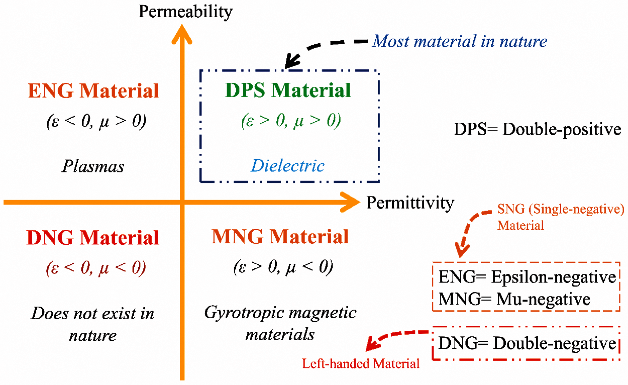
Figure 1: Classification of metamaterials [1]
The common MTMs structures are usually developed in terms of complementary split-ring resonators (CSRR) [7], split-ring resonators (SRRs) [8], planar pattern, and capacitance-loaded strip (CLS) [5]. Apart from these, there are other kinds of MTM structures as discussed in [9] which include electromagnetic bandgap (EBG) and artificial magnetic conductor (AMC). Researchers have employed MTMs in various applications such as wireless health monitoring [10], invisibility cloaking [11], RFID tags [12], filters [13], sensors [14], and EM wave absorbers [15]. Besides that, MTMs are being used for controlling the performances of wearable antennas, radar, and other microwave applications due to their exotic properties [15]. MTMs have also been reported to improve wireless body area network (WBAN) antennas in terms of gain, radiation patterns, bandwidth (BW), and size compactness [7,9,16]. Different types of materials exhibit different EM properties. For example, researchers in [17] experimented with identical dimension and boundary conditions for two different materials. However, the extracted results have shown different properties for the rigid and flexible materials. Furthermore, the MTM can be used for microwave and terahertz fields devices such as antennas, filters, integrated network sensors, or new superstrate layers to improve parameters or equipment in the different field of science and technology (see Fig. 2) [16,18–21]. The knowledge of metamaterials provides vast possibilities for applying and translating the physical concepts of metamaterials from laboratories to innovative practical engineering applications [22].
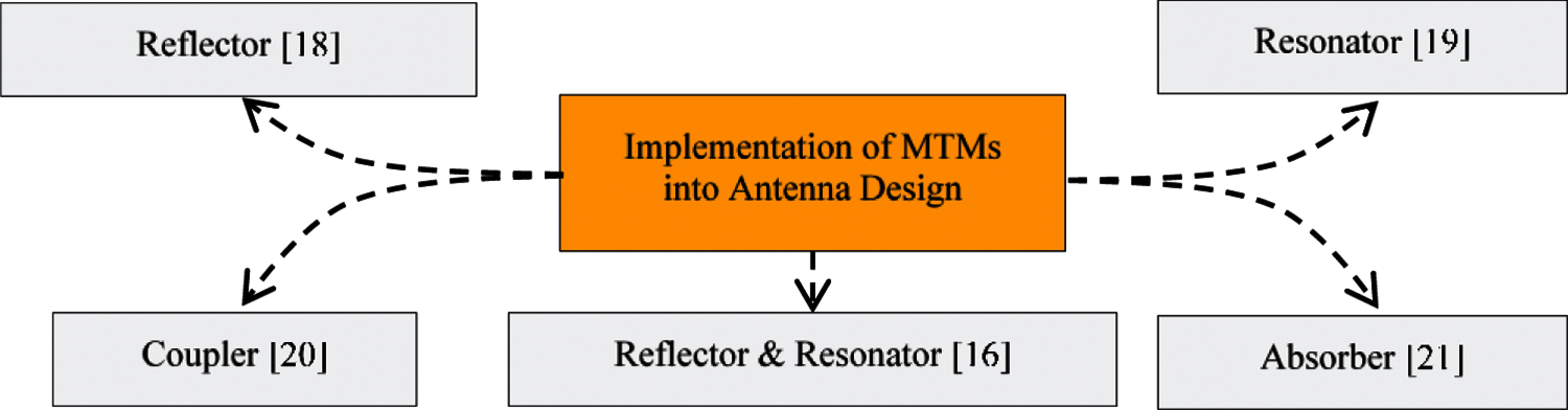
Figure 2: Example of MTMs in different antenna applications
The development of textile fabrics such as embroidered fabric material, sewn textile materials, woven fabrics, nonwoven textile, spinning fabrics, knitted fabrics, braiding, printed fabrics, chemically treated fabrics, and laminated fabrics have been extensively studied throughout the previous decades [23]. Devices and smart sensors have been the focus in the past decade to enable them to be readily integrated into the human body [24]. Electronic functionalities can now be integrated into fabrics with the miniaturisation of electronic components and the development of emerging technologies [25,26]. In recent years, the creation of new textile-based sensors are focused on areas such as health tracking [22], emergency rescue and law enforcement [27], and athletic training [28]. However, designing textile-based MTMs has been challenging as due to their flexible nature and fabrication complexity [23,29,30]. Based on literature survey, it is noticeable that there have been limited research performed on textile MTMs. For instance, Negi et al. studied a CSRR flexible FR4 based MNG MTM [21]. The reported work exhibits negative index bandwidth of 2 GHz (from 7.2 to 9.2 GHz). However, the MTM is not suitable for wearable applications (i.e., wearable sensors/antenna applications) as a rigid substrate was used besides the limited BW. Another pioneering work by Greinke et al. [31] proposed textile material-based MTMs and studied their feasibility for practical applications. However, the extracted material parameters for the MTM reported in the work does not exhibit negative index results.
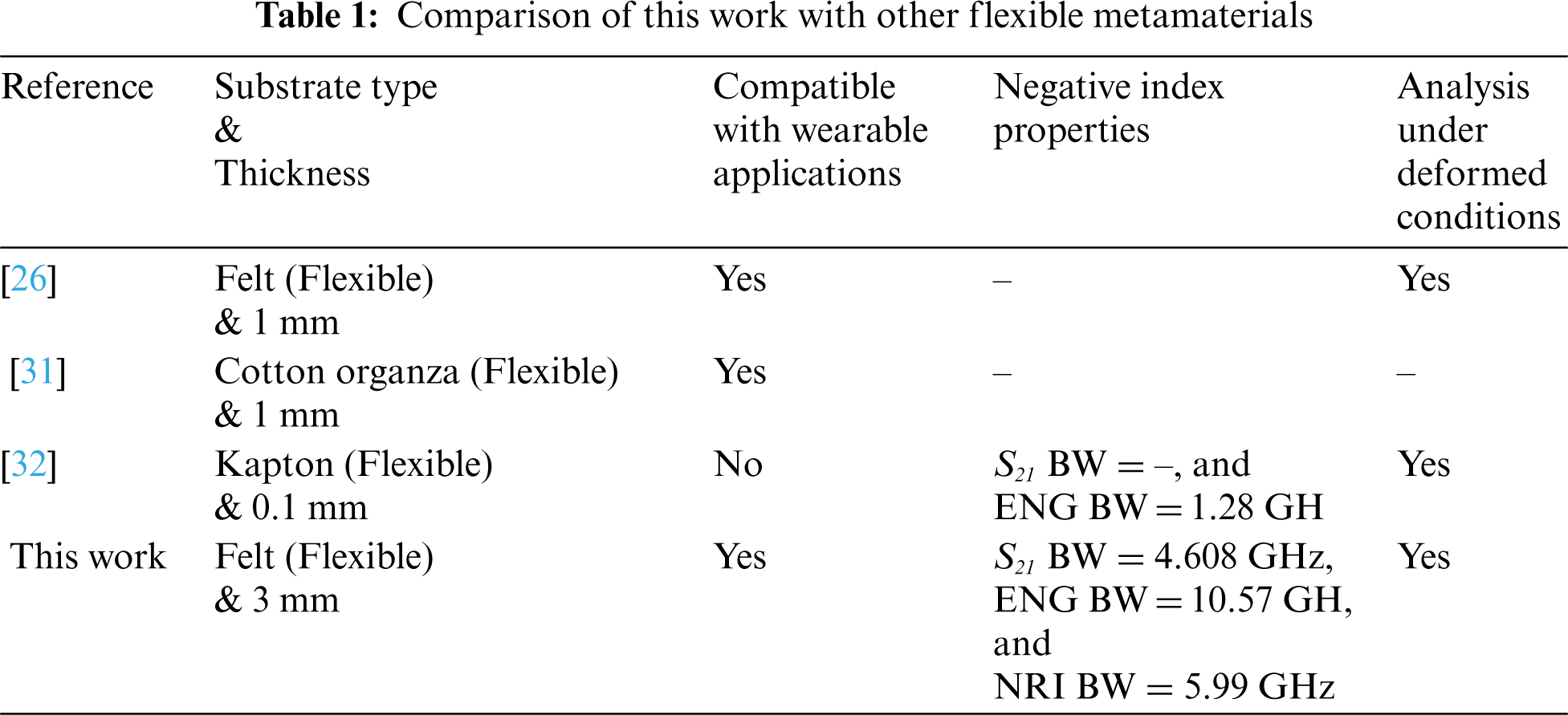
This paper proposes a flexible, negative index (i.e., negative refractive index (NRI) and epsilon negative) textile based MTM. It was designed based on a decagonal-shaped complementary split-ring resonator. To extract the parameters of the MTMs, the robust reflection-transmission (RTR) method was adopted. Both simulations and measurements showed negative-index characteristics, where the measured transmission coefficient (S21) within the range of 1.7 to 3.88 GHz and 6.68 to 7.4 GHz; ENG within the range of 1.7 to 4.13 GHz and 5.6 to 6.38 GHz; and NRI within the range of 2.68 to 5.69 GHz. Simulations showed that the MTM exhibited S21, ENG, and NRI properties within the range of 1.7 to 5.81 GHz and 5.3 to 5.81 GHz; 1.7 to 7.52 GHz and 7.96 to 8.2 GHz; and 1.7 to 2.23 GHz, 2.33 to 5.09 GHz and 5.63 to 7.45 GHz, respectively. Tab. 1 compares the proposed work against various related MTMs found in the literature, indicating the MTM's unique, flexible characteristics.
2 Metamaterial Unit Cell Design
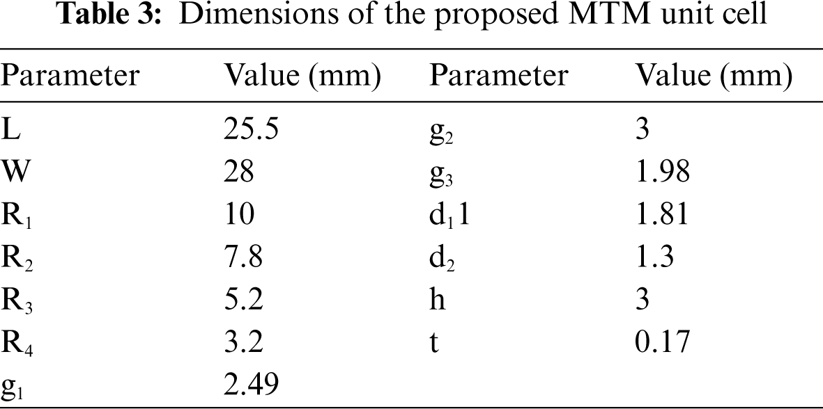
The proposed MTM unit cell was simulated and manufactured using flexible textiles. ShieldIt SuperTM conductive textile from LessEMF Inc. was used to construct the MTM, with felt as the substrate. The material specification is tabulated in Tab. 2. The MTM unit cell was simulated using the finite integration technique (FIT) in the Computer Simulation Technology (CST) Microwave Studio Suite (MWS). Several pairs of symmetric decagonal C-shaped complementary split-ring (CSRR) resonators were assembled to enable the unit cell to operate in a wide frequency range. The MTM unit cell design was completed in five different steps as presented in Fig. 3. Step 1 begins with the creation of two decagonal-shaped inner and outer split rings. Followed by steps 2 and 3, in step 4 the formation of a decagonal SRR was completed. After that in the final step (step 5), the designed SRR model was subtracted from the W×L mm2 ShieldIt SuperTM conductive textile conductive material to obtain the proposed CSRR shape. To prevent fabrication complexity, the decagonal-shaped CSRR was considered in this study. Besides, the use of such a CSRR structure has been proven to enhance the negative effective permittivity resonance of the material structure [33]. The proposed MTM with related parameters is illustrated in Fig. 4a–b. Initially, the proposed dimensioned of the MTM was 8 × 8 × 3 mm3, then it has been optimised after the initial fabricated MTM was distorted during the laser cutting process depicted in Fig. 5. It was observed that a minimum tolerance of 1.2 mm is needed to effectively cut the gaps between the rings in the CSRR. Hence, its overall optimised size is 28 × 25.5 × 3 mm3, which were taken into account after fabrication limitations and other dimensions are summarized in Tab. 3.
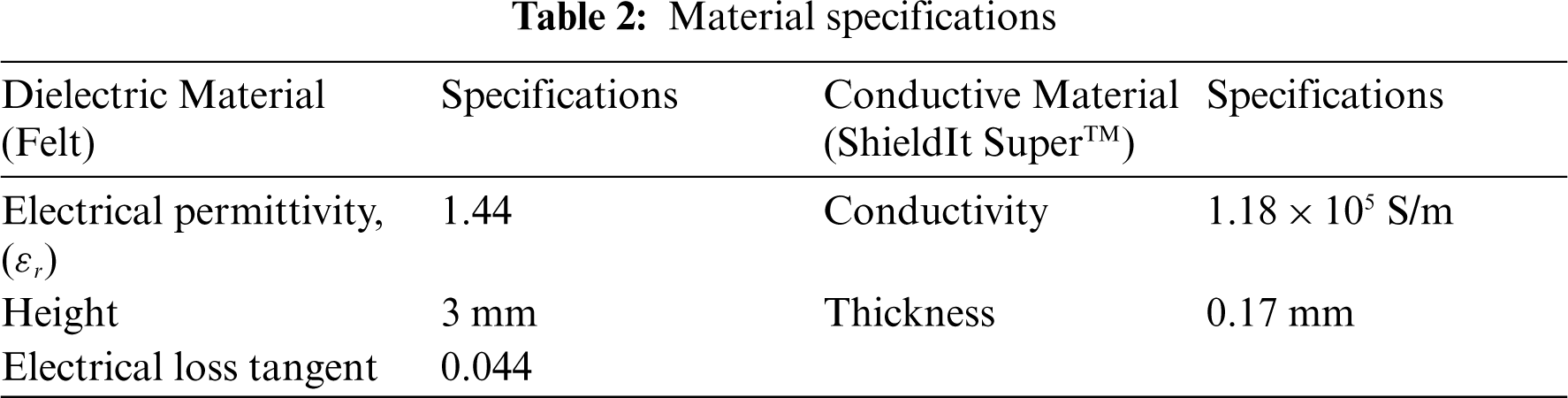
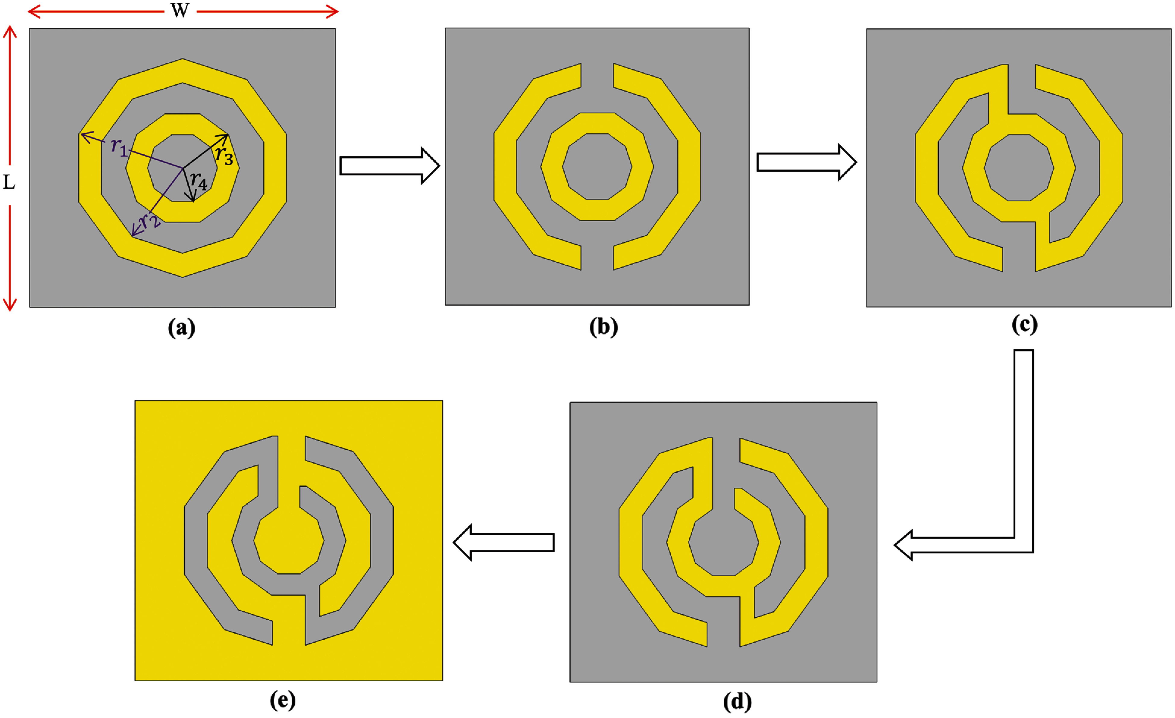
Figure 3: MTM unit cell construction strategies: (a) Step 1, (b) Step 2, (c) Step 3, (d) Step 4, and (e) Step 5

Figure 4: MTM unit cell: (a) Front view, (b) 3D rear view, (c) Equivalent circuit model, and (d) 3D view of the MTM simulation setup to extract effective parameters

Figure 5: Fabrication complexity of the textile slots with the use of the laser cutter
The MTM's equivalent circuit model is shown in Fig. 4c, without accounting the ohmic losses; the reason for this is discussed in [33]. The MTM modelled on a transverse plane acts as an LC resonator, which can be excited by the orthogonal electric field. Conversely, this structure behaves like an electric dipole when excited by an axial electric field. The primary resonant can also be excited by the external magnetic field along with the y-axis, as CSRR can also exhibit a magnetic behaviour. The MTM structure was positioned between two waveguide ports on the positive and negative z-axis and is excited with a transverse electromagnetic (TEM) wave to characterise the MTM effective parameters, as seen in Fig. 3d. It was delimited on the ± x-axis by a Perfect Electric Conductor (PEC) boundary and on the ± y-axis by a Perfect Magnetic Conductor (PMC) boundary. The frequency-domain solver with a tetrahedral mesh scheme in CST Studio Suite was used to simulate this unit cell without a conductive layer at the bottom within the range of 1 to 15 GHz [34].
The MTM is a transverse plane model that functions as an LC resonator that can be excited by an orthogonal electric field. As excited by an axial electric wave, this arrangement behaves like an electric dipole. The main resonant, as well as the y-axis, can be excited by an external magnetic field, as CSRR can exhibit magnetic behaviour [33,35]. By properly modelling the CSRRs gaps, the MTM properties can be tailored. Based on the setup shown in Fig. 3d, the surface current distribution of the proposed MTM was further analysed, and the findings are described in the following section.
The surface current distributions were studied at distinct frequencies to explain the proposed MTM's physical operation when placed in an electric and magnetic field region. Fig. 6 illustrates the surface current distribution of the MTM unit cell at 1 GHz, 2 GHz, 5 GHz, and 6 GHz. The arrows show the actual propagation path in the overall layout, whereas the colours reflect the strength. Strong surface currents can be seen throughout the MTM structure, especially at the edges and corners of the inner CSRR C-shaped structure. The current flows in opposite directions with respect to the upper and bottom sides of the C-shaped slot, which nullify the overall currents and create multiple stopbands. Generally, the use of several slots to attain multiple stopbands operation has been well analysed and described in the literature [36,37]. The decagonal C-shaped slot in the proposed MTM perturbs the current distribution, thus strong surface currents concentrate on the edges of these slots and creating additional resonances. Additionally, the surface current distribution is particularly fluctuant in the symmetrical decagonal C-shaped outer and middle slot regions, whereas currents flow in two distinct directions. Likewise, those two anti-symmetric conductor currents were found at the resonance, which can result in a magnetic moment, from which the proposed structure's unique artificial magnetism is formed, resulting in the metamaterial structure's impactful negative permeability and permittivity, hence, negative refractive index.
The simulated S-parameters (simulated reflection coefficients (S11) and transmission coefficients) are shown in Fig. 7 for the unit cell of the MTM along with 1 × 2, 2 × 2, and 2 × 2 arrays conditions. Prior to the analysis of the MTM effective parameters, stopband behaviour was first investigated to enable the proposed MTM to be operated in different microwave applications [16,38]. From the S-parameters, it could be observed that the stopbands are created when the S21 results are below −10 dB, and the S11 results are near to zero. For different unit cell array conditions, the stopbands were realised approximately from 1 to 3.87 GHz, 5.3 to 5.81 GHz, 11.88 to 12.24 GHz, and 14.132 to 15 GHz. For the homogeneous slab with infinite periodic structure (e.g., AMC structure), the metamaterial results could be coincided within the accuracy of numerical calculation regardless of the number of unit cells conditions. However, metamaterial in this study is neither homogeneous nor periodically infinite [39]. The RTR method was utilised in this study to extract material effective parameters (permittivity, permeability, and refractive index) based on [30,40] the MTM's S-parameters for both simulations and experiments.

Figure 6: Surface current distribution on the MTM unit cell at different resonances

Figure 7: Simulated S-parameters
Figs. 8 and 9 depict the simulated real and imaginary parts of the effective permittivity and refractive index, respectively for the unit cell of the MTM along with 1 × 2, 2 × 2, and 2 × 2 arrays conditions. As shown in Fig. 8, the real negative permittivity (ε) value for different array conditions approximately ranges from 1 to 7.52 GHz, from 7.96 to 8.43 GHz, from 9.18 to 9.39 GHz, from 11.12 to 12.31 GHz, from 12.59 to 13.74 GHz, and from 13.97 to 15 GHz. It is shown in Fig. 9 that the NRI regions are exhibited for different array conditions are approximately from 1 to 2.23 GHz, 2.33 to 5.09 GHz, 5.63 to 7.45 GHz, and 13.55 to 13.73 GHz. Since the MTM in this study was neither homogeneous nor periodically infinite, it has exhibited slight discrepancies in S-parameters for different array conditions. It also implies that this leads to slight discrepancies in MTM effective parameters as these parameters were extracted from the S-parameters. Again, considering it is possible to assign a set of equivalent material properties to every MTM slab, no matter how coarse the structure of the slab may be. However, in order for these to be useful material properties when structural periodicity is involved, the periodicity must be extremely short in comparison to the wavelength [41].

Figure 8: Simulated MTM permittivity

Figure 9: Simulated MTM refractive index
Next, the characteristics of MTM structures are evaluated since they are implemented on flexible materials. The MTM's efficiency is tested in deformed conditions, including multiple bent positions which potentially will occur on clothing due to human body anatomy and postures. The physical deformations of the MTMs (elongation or bending) potentially resulting in changes of the MTM EM properties [26,30], are depicted in Fig. 10.
The effective parameters and the S21 result of the MTM under distinctive bending radii (r) were then studied, with their changes in resonant frequency shown in Figs. 11 and 12. The proposed design's effective length varied as a result of bending; thus, there were changes to its resonance frequency. The more the proposed MTM was bent, the shorter the resonant length became, and the resonant frequency became higher. The bending also affected the effective surface current length, hence, the electromagnetic behaviour of the MTM. When the MTM was bent at the x-axis (Fig. 11), the EM properties were significantly changed. On the other hand, when the bending analysis was performed at the y-axis, changes in the MTM EM properties were insignificant (please see Fig. 12). The discrepancies between the results of x-axis bending and y-axis bending were due to the differences in surface current distribution. Nonetheless, the MTM still exhibited the required ENG and NRI characteristics with different bending conditions within the frequencies of interest.

Figure 10: Bending at different radii at the (a) x-axis and (b) y-axis. (c) 3D deformation of the MTM structure
Fig. 13a depicts the fabricated prototype used in the experimental validations, performed using a laser cutter to ensure dimensioning accuracy. The outline of the final design was first exported into a Drawing Exchange Format (DFX) file, which was then used as an input into the laser cutter to dimension the ShieldIt SuperTM textile, see Fig. 13b. The dimensioned ShieldIt textile was then heated using a clothing iron to secure it to the felt substrate [30,42].
Next, measurements were conducted using an Agilent Technologies E5071C network analyser to measure its S-parameters. Four different sets of standard horn antennas were used to test the MTM [43,44]: WR430, which operates within 1.7 to 2.6 GHz; WR284, which operates within 2.6 to 3.95 GHz; WR187, which operates within 3.95 to 5.85 GHz; and WR137, which operates within 5.85 to 8.20 GHz. The MTM was mounted in between the horn antennas for measurements, as shown in Fig. 14. Threads and clear tapes were used to secure the proposed MTM between the horn antennas during measurements, without placing the horn antennas in the anechoic chamber. The distance between each pair of horn antennas was kept to a minimum during measurements. All the scattering data were integrated within the frequency range of 1.7 to 8.2 GHz after the MTM measurements were completed. Finally, the RTR approach was used to retrieve the MTM's parameters.

Figure 11: Effects of bending with different radii (r) at the x-axis: (a) S21 result, (b) Permittivity, and (c) refractive index
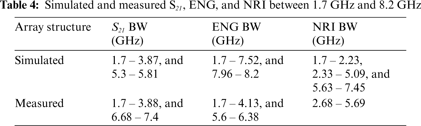
The measured S21, ε, and refractive index of the MTM are depicted in Figs. 15, 16 and 17, respectively. Results showed an S21 BW of 2.9 GHz (from 1.7 to 3.88 GHz, and from 6.68 to 7.4 GHz), and this is in good agreement with simulations, with a simulated S21 BW of 2.68 GHz. On the other hand, the measured ENG BW is 3.32 GHz (from 1.7 to 4.13 GHz, and from 5.6 to 6.38 GHz), whereas simulations indicated that this ENG BW is 6.06 GHz. Finally, an NRI BW of 3.01 GHz was obtained from measurements (from 2.68 to 5.69 GHz), whereas simulations indicated an NRI BW of 5.11 GHz. The attained negative index regions in measurements are highlighted in grey. All results between 1.7 GHz and 8.2 GHz are summarised in Tab. 4. Furthermore, the measured S21 BW increased by 150 MHz whereas the second resonance band increased by 90 MHz, with the starting frequency of the second band shifting from 5.3 GHz to 6.68 GHz. Similarly, the ENG BW decreased by 2.85 GHz in measurements, where the first ENG band is narrower by 3.39 GHz, and the frequency of the second band is lowered, starting from 5.6 GHz instead of 7.96 GHz (in simulations). On the contrary, the measured NRI BW decreased by 2.1 GHz compared to the simulations, and measurements indicated the shifting of the starting frequency to a higher frequency by 980 MHz. However, the simulated NRI is triband, whereas measurements exhibited a dual band operation.

Figure 12: Effects of bending with different radii (r) at the y-axis: (a) S21 result, (b) Permittivity, and (c) Refractive index

Figure 13: (a) Fabricated prototype of the proposed MTM structure. (b) Under the process of laser cutting

Figure 14: Measurement setup. (a) Schematic representation of the measurement setup, and (b) Photos of the material under test (MUT) located between the horn antennas. WR284 standard horn antennas and waveguide adapters were used

Figure 15: Measured S21 results

Figure 16: Measured permittivity

Figure 17: Measured refractive index
A full textile flexible MTM was developed and demonstrated in this paper. The unit cell of the MTM consists of a several pairs of symmetric decagonal C-shaped CSRR resonators. The operation of this textile MTM was validated using simulations and experimental validations, with a negative index characteristic was observed within the S and C bands. On the other hand, simulated ENG characteristics were observed within the X-band. Apart from that, drawbacks pertaining to fabrication complexity was highlighted in the paper as dimension of the textile-based structure should be considered during design process. The proposed MTM has the potential to implement into the antenna design to enhance gain, improve bandwidth, mitigate mutual coupling effectively and reduction in specific absorption rate. Furthermore, the MTM can be utilised for sensor application for wireless body sensor networks. Moreover, upcoming research will be foreseen to be concentrated on the implementation of the proposed MTM to design a compact MTM-based antenna for medical application.
Funding Statement: This work was supported in part by the King Mongkut's University of Technology North Bangkok (Grant no: KMUTNB-64-KNOW-12), and in part by the by the Academy of Finland 6Genesis Flagship (Grant no: 318927).
Conflicts of Interest: The authors declare that they have no conflicts of interest to report regarding the present study.
1. N. Engheta and R. W. Ziolkowski, “Introduction, history, and selected topics in fundamental theories of metamaterials,” In Metamaterials: Physics and Engineering Explorations, 1st ed., vol. 1. Hoboken, New Jersey, USA: John Wiley & Sons, Inc., pp. 1–41, 2006. [Google Scholar]
2. D. R. Smith, S. Schultz, P. Markoš and C. M. Soukoulis, “Determination of effective permittivity and permeability of metamaterials from reflection and transmission coefficients,” Physical Review B, vol. 65, no. 19, pp. 195104, 2002. [Google Scholar]
3. D. R. Smith, W. J. Padilla, D. C. Vier, S. C. Nemat-Nasser and S. Schultz, “Composite medium with simultaneously negative permeability and permittivity,” Physical Review Letters, vol. 84, no. 18, pp. 4184–4187, 2000. [Google Scholar]
4. H. Yalduz, B. Koç, L. Kuzu and M. Turkmen, “An ultra-wide band low-sAR flexible metasurface-enabled antenna for WBAN applications,” Applied Physics A, vol. 125, no. 9, pp. 1–11, 2019. [Google Scholar]
5. M. K. Khandelwal, A. Arora, S. Kumar, K. W. Kim and H. C. Choi, “Dual band double negative (DNG) metamaterial with small frequency ratio,” Journal of Electromagnetic Waves and Applications, vol. 32, no. 17, pp. 2167–2181, 2018. [Google Scholar]
6. H. Singh, B. S. Sohi and A. Gupta, “A compact CRLH metamaterial with wide band negative index characteristics,” Bulletin of Materials Science, vol. 42, no. 4, pp. 1–11, 2019. [Google Scholar]
7. S. Ahdi Rezaeieh, M. A. Antoniades and A. M. Abbosh, “Gain enhancement of wideband metamaterial-loaded loop antenna with tightly coupled arc-shaped directors,” IEEE Transactions on Antennas and Propagation, vol. 65, no. 4, pp. 2090–2095, 2017. [Google Scholar]
8. A. Alemaryeen and S. Noghanian, “Crumpling effects and specific absorption rates of flexible AMC integrated antennas,” IET Microwaves, Antennas & Propagation, vol. 12, no. 4, pp. 627–635, 2018. [Google Scholar]
9. M. M. T. Islam, M. M. T. Islam, M. Samsuzzaman and M. R. I. Faruque, “Compact metamaterial antenna for UWB applications,” Electron. Letters, vol. 51, no. 16, pp. 1222–1224, 2015. [Google Scholar]
10. S. Zahertar, Y. Wang, R. Tao, J. Xie, Y. Q. Fu et al., “A fully integrated biosensing platform combining acoustofluidics and electromagnetic metamaterials,” Journal of Physics D: Applied Physics, vol. 52, no. 48, pp. 485004, 2019. [Google Scholar]
11. M. Naserpour, C. J. Zapata-Rodríguez, S. M. Vuković, H. Pashaeiadl and M. R. Belić, “Tunable invisibility cloaking by using isolated graphene-coated nanowires and dimers,” Scientific Reports, vol. 7, no. 1, pp. 1–14, 2017. [Google Scholar]
12. A. F. M. Fazilah, M. Jusoh, T. Sabapathy, Q. H. Abbasi, K. Hossain et al., “A flexible and compact metamaterial UHF RFID Tag for remote sensing in human health,” in Int. Conf. on UK-China Emerging Technologies, Glasgow, Scotland, UK, pp. 1–4, 2020. [Google Scholar]
13. A. K. Panda, M. Pattnaik and R. Swain, “CSRR embedded CPW band-stop filter,” IETE Journal of Research, pp. 1–7, 2019. https://doi.org/10.1080/03772063.2019.1684847. [Google Scholar]
14. A. Salim and S. Lim, “Review of recent metamaterial microfluidic sensors,” Sensors, vol. 18, no. 1, pp. 232, 2018. [Google Scholar]
15. M. M. Bait-Suwailam, T. S. Almoneef and A. Alomainy, “A dual-band flexible frequency-reconfigurable metamaterial absorber using modified split-ring resonator,” in 2nd IEEE Middle East and North Africa COMMunications Conf., Manama, Bahrain, pp. 1–4, 2019. [Google Scholar]
16. S. S. Al-Bawri, H. H. Goh, M. S. Islam, H. Y. Wong, M. F. Jamlos et al., “Compact ultra-wideband monopole antenna loaded with metamaterial,” Sensors, vol. 20, no. 3, pp. 796, 2020. [Google Scholar]
17. E. Ahamed, M. M. Hasan, M. R. I. Faruque, M. F. B. Mansor, S. Abdullah et al., “Left-handed metamaterial inspired by joint TD geometry on flexible nial2o4 substrate,” PLoS One, vol. 13, no. 6, pp. 1–28, 2018. [Google Scholar]
18. S. S. Al-Bawri, M. S. Islam, H. Y. Wong, M. F. Jamlos, A. Narbudowicz et al., “Metamaterial cell-based superstrate towards bandwidth and gain enhancement of quad-band CPW-fed antenna for wireless applications,” Sensors, vol. 20, no. 2, pp. 1–14, 2020. [Google Scholar]
19. M. T. Islam, M. Samsuzzaman, M. T. Islam and S. Kibria, “Experimental breast phantom imaging with metamaterial-inspired nine-antenna sensor array,” Sensors, vol. 18, no. 12, pp. 4427, 2018. [Google Scholar]
20. M. D. J. Alam, E. Ahamed, M. R. I. Faruque, M. T. Islam and A. M. Tamim, “Left-handed metamaterial bandpass filter for GPS, earth exploration-satellite and WiMAX frequency sensing applications,” PLoS One, vol. 14, no. 11, pp. e0224478, 2019. [Google Scholar]
21. D. Negi, R. Khanna and J. Kaur, “Design and performance analysis of a conformal CPW fed wideband antenna with Mu-negative metamaterial for wearable applications,” International Journal of Microwave and Wireless Technologies, vol. 11, no. 8, pp. 806–820, 2019. [Google Scholar]
22. J. F. Saenz-Cogollo, M. Pau, B. Fraboni and A. Bonfiglio, “Pressure mapping mat for tele-home care applications,” Sensors, vol. 16, no. 3, pp. 365, 2016. [Google Scholar]
23. K. Zhang, P. J. Soh and S. Yan, “Meta-wearable antennas—A review of metamaterial based antennas in wireless body area networks,” Materials, vol. 14, no. 1, pp. 149, 2020. [Google Scholar]
24. X. Tian, P. M. Lee, Y. J. Tan, T. L. Y. Wu, H. Yao et al. “Wireless body sensor networks based on metamaterial textiles,” Nature Electronics, vol. 2, no. 6, pp. 243–251, 2019. [Google Scholar]
25. M. Martinez-Estrada, B. Moradi, R. Fernández-Garcia and I. Gil, “Impact of manufacturing variability and washing on embroidery textile sensors,” Sensors, vol. 18, no. 11, pp. 3824, 2018. [Google Scholar]
26. B. Moradi, R. Fernández-García and I. Gil, “E-textile embroidered metamaterial transmission line for signal propagation control,” Materials, vol. 11, no. 6, pp. 955, 2018. [Google Scholar]
27. G. Tartare, X. Zeng and L. Koehl, “Development of a wearable system for monitoring the firefighter's physiological state,” In IEEE Industrial Cyber-Physical Systems, St. Petersburg, Russia, pp. 561–566, 2018. [Google Scholar]
28. J. F. Wu, C. Qiu, Y. Wang, R. Zhao, Z. P. Cai et al. “Human limb motion detection with novel flexible capacitive angle sensor based on conductive textile,” Electronics, vol. 7, no. 9, pp. 192, 2018. [Google Scholar]
29. K. Hossain, T. Sabapathy, M. Jusoh, M. A. Abdelghany, P. J. Soh et al. “A negative index nonagonal CSRR metamaterial-based compact flexible planar monopole antenna for ultrawideband applications using viscose-wool felt,” Polymers, vol. 13, no. 16, pp. 2819, 2021. [Google Scholar]
30. K. Hossain, T. Sabapathy, M. Jusoh, P. J. Soh, M. H. Jamaluddin et al. “Electrically tunable left-handed textile metamaterial for microwave applications,” Materials, vol. 14, no. 5, pp. 1274, 2021. [Google Scholar]
31. B. Greinke, M. Candotti, A. Alomainy and C. Parini, “Parameters extraction of three-dimensional structures for graded textile cloaking materials,” in Loughborough Antennas & Propagation Conf., Loughborough, UK, pp. 84–87, 2013. [Google Scholar]
32. T. Shaw and D. Mitra, “Design of miniaturized, low-loss and flexible multi-band metamaterial for microwave application,” Applied Physics A, vol. 124, no. 4, pp. 1–11, 2018. [Google Scholar]
33. J. D. Baena, J. Bonache, F. Martín, R. M. Sillero, F. Falcone, T. Lopetegi, M. A. G. Laso, J. Garcia-Garcia, I. Gil, M. F. Portillo and M. Sorolla “Equivalent-circuit models for splitringresonators and complementary split-ring resonators coupled to planar transmission lines,” IEEE Transactions on Microwave Theory and Techniques, vol. 53, no. 4, pp. 1451–1460, 2005. [Google Scholar]
34. T. M. Hossain, M. A. F. Jamlos, M. A. F. Jamlos, P. J. Soh, M. I. Islam et al. “Modified H-shaped DNG metamaterial for multiband microwave application,” Applied Physics A, vol. 124, no. 2, pp. 1–7, 2018. [Google Scholar]
35. Y. Dong, H. Toyao and T. Itoh, “Design and characterization of miniaturized patch antennas loaded with complementary split-ring resonators,” IEEE Transactions on Antennas and Propagation, vol. 60, no. 2, pp. 772–785, 2012. [Google Scholar]
36. A. Kunwar, A. K. Gautam, and K. Rambabu, “Design of a compact U-shaped slot triple band antenna for WLAN/WiMAX applications,” AEU - International Journal of Electronics and Communications, vol. 71, pp. 82–88, 2017. [Google Scholar]
37. S. Verma and J. A. Ansari, “Analysis of U-slot loaded truncated corner rectangular microstrip patch antenna for broadband operation,” AEU - International Journal of Electronics and Communications, vol. 69, no. 10, pp. 1483–1488, 2015. [Google Scholar]
38. T. Shabbir, M. T. Islam, S. S. Al-Bawri, R. W. Aldhaheri, K. H. Alharbi et al. “16-port Non-planar MIMO antenna system with near-zero-index (NZI) metamaterial decoupling structure for 5G applications,” IEEE Access, vol. 8, pp. 157946–157958, 2020. [Google Scholar]
39. X. Chen, T. M. Grzegorczyk, B. I. Wu, J. Pacheco, and J. A. Kong, “Robust method to retrieve the constitutive effective parameters of metamaterials,” Physical Review E, vol. 70, no. 1, pp. 016608, 2004. [Google Scholar]
40. A. B. Numan and M. S. Sharawi, “Extraction of material parameters for metamaterials using a full-wave simulator [education column],” IEEE Antennas and Propagation Magazine, vol. 55, no. 5, pp. 202–211, 2013. [Google Scholar]
41. S. Arslanagić, T. V. Hansen, N. A. Mortensen, A. H. Gregersen, O. Sigmund et al. “A review of the scattering-parameter extraction method with clarification of ambiguity issues in relation to metamaterial homogenization,” IEEE Antennas and Propagation Magazine, vol. 55, no. 2, pp. 91–106, 2013. [Google Scholar]
42. T. Sabapathy, P. J. Soh and M. Jusoh, “A three-year improvement assessment of project-based learning for an antennas and propagation course [education corner],” IEEE Antennas and Propagation Magazine, vol. 62, no. 6, pp. 76–84, 2020. [Google Scholar]
43. M. M. Hasan, M. R. I. Faruque and M. T. Islam, “Compact left-handed meta-atom for S-, C- and Ku-band application,” Applied Sciences, vol. 7, no. 10, pp. 1071, 2017. [Google Scholar]
44. Z. Li, R. Zhao, T. Koschny, M. Kafesaki, K. Alici et al. “Chiral metamaterials with negative refractive index based on four ‘U’ split ring resonators,” Applied Physics Letters, vol. 97, no. 8, pp. 2010–2013, 2010. [Google Scholar]
 | This work is licensed under a Creative Commons Attribution 4.0 International License, which permits unrestricted use, distribution, and reproduction in any medium, provided the original work is properly cited. |