DOI:10.32604/cmc.2022.021751
| Computers, Materials & Continua DOI:10.32604/cmc.2022.021751 | |
| Article |
Inkjet Printed Metamaterial Loaded Antenna for WLAN/WiMAX Applications
1Department of Electrical Engineering, Polytechnique Montréal, Montréal, QC H3T 1J4, Canada
2Space Science Centre (ANGKASA), Institute of Climate Change (IPI), Universiti Kebangsaan Malaysia, Bangi, 43600, Selangor, Malaysia
3Department of Electrical, Electronic and Systems Engineering, Faculty of Engineering and Built Environment, Universiti Kebangsaan Malaysia, Malaysia
*Corresponding Author: Touhidul Alam. Email: touhidul@ukm.edu.my
Received: 13 July 2021; Accepted: 01 September 2021
Abstract: In this paper, the design and performance analysis of an Inkjet-printed metamaterial loaded monopole antenna is presented for wireless local area network (WLAN) and worldwide interoperability for microwave access (WiMAX) applications. The proposed metamaterial structure consists of two layers, one is rectangular tuning fork-shaped antenna, and another layer is an inkjet-printed metamaterial superstate. The metamaterial layer is designed using four split-ring resonators (SRR) with an H-shaped inner structure to achieve negative-index metamaterial properties. The metamaterial structure is fabricated on low-cost photo paper substrate material using a conductive ink-based inkjet printing technique, which achieved dual negative refractive index bands of 2.25–4.25 GHz and 4.3–4.6 GHz. The antenna is designed using a rectangular tuning fork structure to operate at WLAN and WiMAX bands. The antenna is printed on 30 × 39 × 1.27 mm3 Rogers RO3010 substrate, which shows wide impedance bandwidth of 0.75 GHz (2.2 to 2.95 GHz) with 2 dB realized gain at 2.4 GHz. After integrating metamaterial structure, the impedance bandwidth becomes 1.25 GHz (2.33 to 3.58 GHz) with 2.6 dB realized gain at 2.4 GHz. The antenna bandwidth and gain have been increased using developed quad SRR based metasurface by 500 MHz and 0.6 dBi respectively. Moreover, the proposed quad SRR loaded antenna can be used for 2.4 GHz WLAN bands and 2.5 GHz WiMAX applications. The contribution of this work is to develop a cost-effective inject printed metamaterial to enhance the impedance bandwidth and realized the gain of a WLAN/WiMAX antenna.
Keywords: Metamaterial; epsilon negative; antenna; split ring resonator; WiMAX; WLAN
The development of modern wireless communication systems requires multi-band antennas for wireless service requirements. Wireless local area network (WLAN) and worldwide interoperability for microwave access (WiMAX) have been widely applied in handheld computers and smartphones. For improved high-speed data connectivity, allowing users mobility and low-cost viable communication, these two technologies have been widely acknowledged. According to IEEE standard 802.11, WLAN standards consist of 2.4 GHz (2.4–2.484 GHz), 5.2 GHz (5.15–5.35 GHz) frequency bands. WiMAX standards consist of 2.5, 3.5 GHz (3.3–3.6 GHz) and 5.5-GHz (5.25–5.85 GHz) frequency bands as stated in the IEEE standard 802.16d, 802.16e. Because of the rapid development, the necessity of designing compact antennas with low cost, ease of integration and multiband operation is in great demand [1–3]. The multi-band antennas can reduce the number of required antennas and also improve the electromagnetic compatibility of the wireless systems. Microstrip patch antennas (MPAs) have been playing a very important role in wireless communication technologies as they are lightweight, easy fabrication and integrability to mounting hosts.
In recent times, several methods have been reported on the development of compact dual-band antennas. However, most of them do not provide the desired bandwidths. Many studies on multiband antennas for wireless communication systems have been reported by using conventional methods such as a monopole antenna [4,5], dipole antenna [6], slot antennas [7,8], the co-planar antenna [9] and fractal antenna [10]. Though, they still have a large size corresponding to the wavelength at their operating frequencies and small bandwidth with low gain. To overcome the limitations of the microstrip patch antennas some approaches have been proposed such as changing substrate permittivity and thickness [11], stacked dielectric resonator antenna [12,13], metamaterial embedded microstrip patch antenna [14,15] to improve the gain and bandwidth of the antenna.
In recent years for improving the performance of antennas, metamaterials have attracted considerable attention [16–18]. These metamaterials have been developed with unique electromagnetic properties that cannot be found in nature, such as negative permittivity and negative permeability that lead to negative refractive index. A split-ring resonator (SRR) is the fundamental unit-cell to obtain negative permeability which is absent in normal materials [19]. A complementary split-ring resonator (CSRR) is another structure to design stopband frequency band characteristics [20]. These structures have been widely used to design the miniaturized antenna, gain enhancement and multiband applications [21–24]. Metamaterial inspired microstrip patch antennas can be controlled more conveniently because of their electrically small size and subwavelength profile which does not affect other antenna parameters. In [25], a split ring resonator-based metamaterial superstrate has been used to enhance the gain of the patch antenna. Metamaterial loaded two dipole antennas have been presented in [26] to achieve compact size, dual-band functionalities and good gain. The proposed antennas have gain values of up to 1.9 dBi. A uniplanar compact metamaterial inspired dipole antenna has been designed and proposed for WLAN and WiMAX applications [27]. Two pairs of complementary capacitively-loaded loops produce antenna gain of about 1.3 to 1.5 dBi in the 2.21 to 2.77 GHz frequency band. In this work, a metamaterial inspired antenna is proposed where an array of unit cells form meta-surface and stacked at the back of the antenna using a spacer. This gives the design freedom and tuneability of the antenna parameters by varying the distance and position of the antenna to the meta-surface. The meta-surface act as a reflector that enhances the electrical length of antenna and impact on bandwidth and gain enhancement. Also, the fabrication procedure is interesting and easy and cost-effective.
In this paper, a simple inkjet printed quad split-ring resonator (SRR) loaded multiband antenna has been proposed to cover WLAN and WiMAX applications. Firstly, a printed monopole antenna has been designed to operate at desired frequencies. Secondly, four interconnected split-ring resonators have been printed on photo paper substrate using silver nanoparticle ink. After that, the metamaterial slab has been placed at the back of the antenna to drive the resonant modes for achieving wide impedance bandwidth and improved gain. Numerical results show that, compared to the patch antenna, the realized gain of the proposed antenna gets improved by more than 0.6 dBi within the working band and the impedance bandwidth is increased from 0.61 GHz (2.38–2.99 GHz) to 1.25 GHz (2.33–3.58 GHz). The antenna developed in this paper dominates the smaller area and has simpler geometry to realize the required operating bands compared to other designs stated in the literature.
The structure of the dual-band patch antenna is designed on Rogers RO3010, substrate with relative permittivity of 10.2 and a loss tangent of 0.0022. Initially, a rectangular-shaped tuning fork structure has been designed based on [28,29]. The arm of the tuning fork has been chosen considering quarter wavelength relation with the resonant frequency of 2.4 GHz. The tuning forks on a trapezoid based structure act as a monopole antenna. Besides, the gap between monopole and the partial ground plane has been optimized to adjust input impedance, which can play a significant role to achieve desire frequencies. The configuration of the slotted patch antenna has been schematically shown in Fig. 1. The geometrical parameter of the dual-band antenna has been listed in Tab. 1. The rectangular slotted patch antenna has been fabricated and shown in Fig. 2.
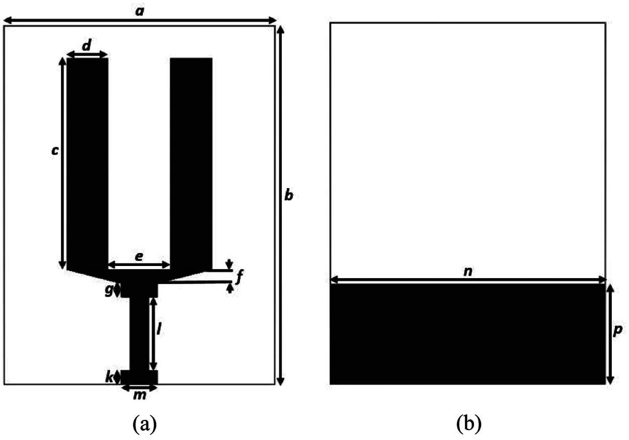
Figure 1: Proposed antenna (a) front view and (b) back view
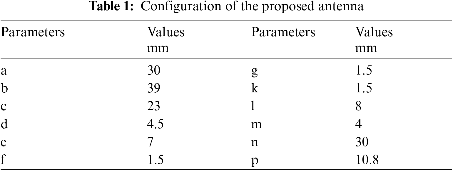
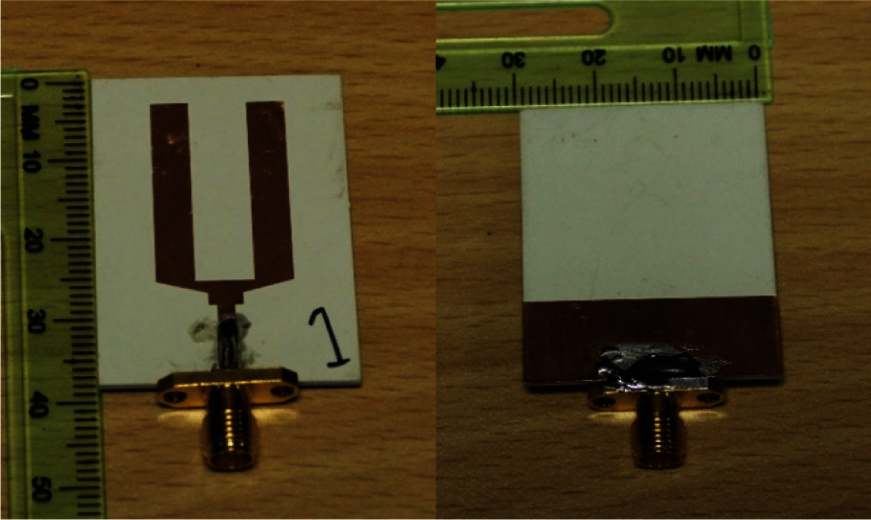
Figure 2: Photograph of the fabricated prototype
The proposed metamaterial unit cell consists of four interconnected split-ring resonators with H-shaped structre as shown in Fig. 3. The splits of the structure form capacitance and the rectangular-shaped lines act as inductance. The resultant capacitance and inductance form resonant frequency. Moreover, the XY symmetrical structure is designed in such a way that it can reflect waves from every angle. The structure of the proposed metamaterial has been printed on a photo paper substrate with relative permittivity of 3.2 and a thickness of 0.54 mm. The photo paper from Epson has been used as a substrate in many articles for inkjet printing [30]. As compared to conventional PCB fabrication, inkjet printing fabrication is more cost-effective and environmentally friendly. A metallic silver nanoparticle ink from AgIC is used as a conductive radiating element. The main feature of this ink is that it dries in a few seconds. The thickness of the metallic ink is 0.0175 mm. A Brother DCP-T310 inkjet printer has been used for printing the structure. The overall dimensions of the structure were 11 mm2 × 11 mm2. The configuration of the quad SRR has been represented in Tab. 2. The final prototype of 4 × 5 quad SRR is shown in Fig. 4.
Figure 3: Proposed quad split-ring resonator
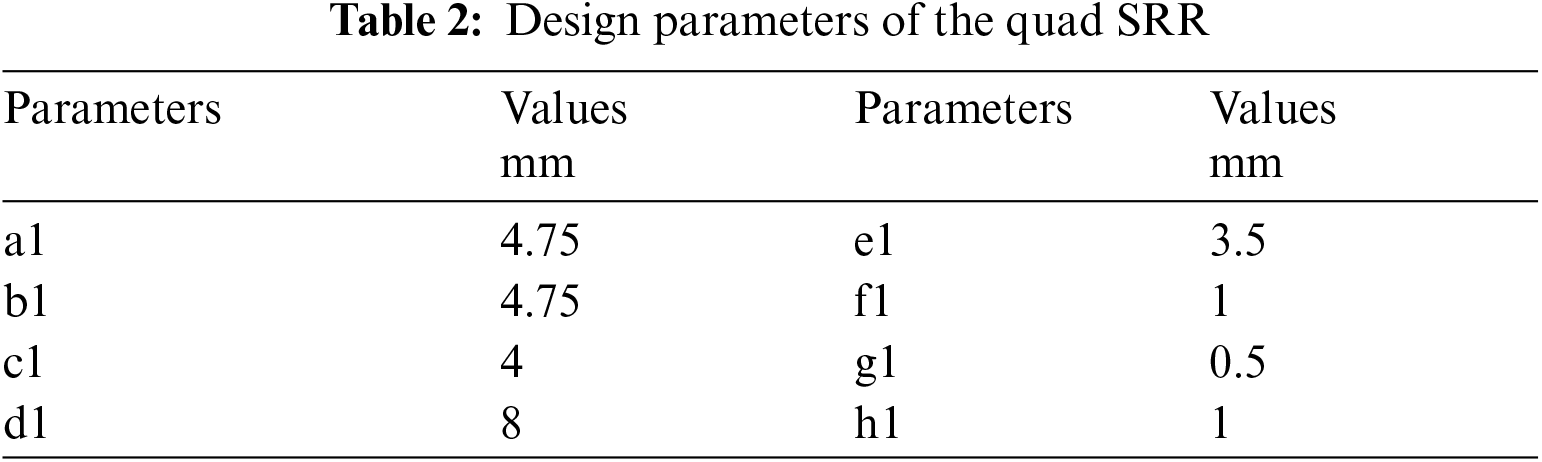
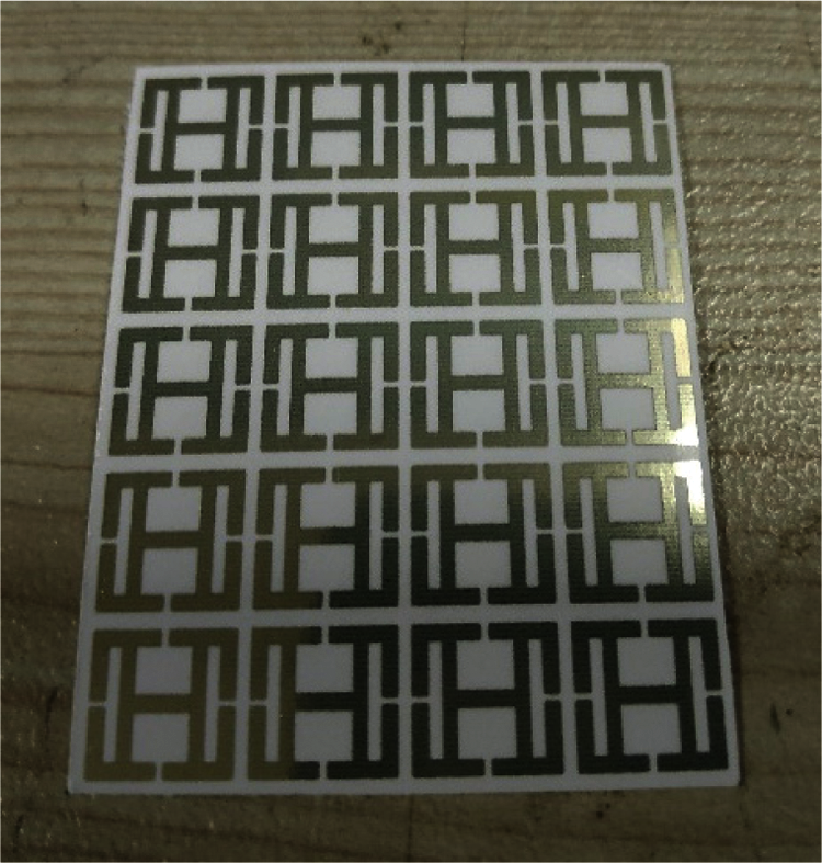
Figure 4: Photograph of the final printed prototype
The Finite Integration Technique method-based CST Microwave Studio has been used to extract the reflection coefficient (S11) and transmission coefficient (S21) of the quad SRR. The design structure is segmented into smaller units and the calculation of each unit is done by solving Maxwell's equation. Perfect electric conductor (PEC) and perfect magnetic conductor (PMC) are set as a boundary condition along x-direction and y-direction and the z-direction is set as open (add space). The effective constitutive parameters of the proposed metamaterial unit cell have been extracted by the transmission-reflection method reflection (TR) method [31–33]. Where, the refractive index η, permittivity ε and permeability μ are obtained by
where k = ω/c is the wave propagation vector, ω is the angular frequency, c is the speed of light and m is an integer that defines the branch index of η. Symbol z represents the impedance and d denotes the thickness of the substrate material. For a continuous refractive index, the fundamental branch index should be zero because the largest dimension of the proposed unit-cell is less than one-sixth of the material wavelength [34].
A set of waveguides to coaxial adapters are used along with the Agilent N5227A performance network analyzer (PNA) as shown in Fig. 5. To ensure the result accuracy, an Agilent N4694-60001 electronic calibration module has also been used to calibrate the PNA.
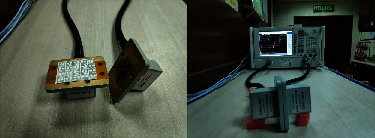
Figure 5: Metamaterial measurement setup
The simulated and measured reflection coefficient (S11) and the transmission coefficient (S21) of the metamaterial structure have been illustrated in Fig. 6. The simulated results have a much better agreement with the measured results. The structure showed a measured passband of 2.17–2.60 GHz (S11 < −10 dB) and a stopband throughout the whole frequency band.
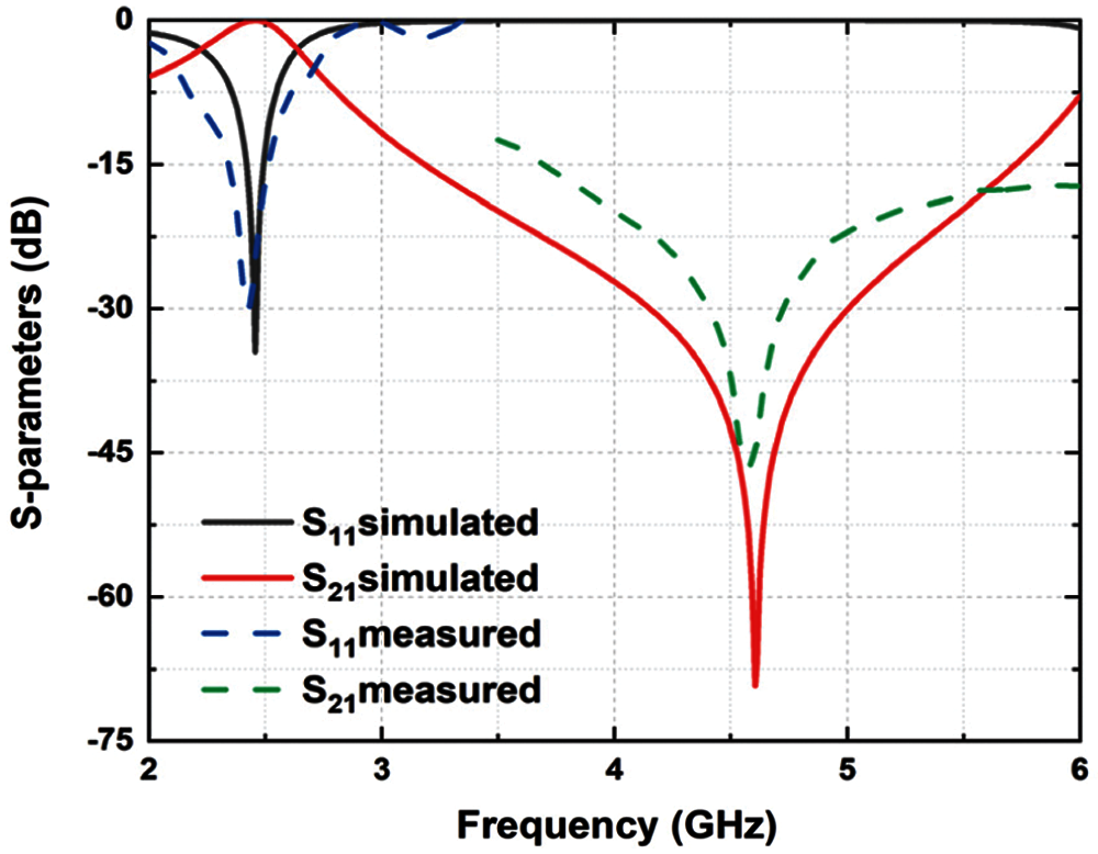
Figure 6: Simulated and measured S-parameters of quad SRR
The effective constitutive parameters of the proposed metamaterial unit cell have been illustrated in Fig. 7. It shows a negative effective permittivity from 2.49 to 4.61 GHz and a negative effective permeability from 2.43 to 2.58 GHz and 4.5 to 6 GHz. The structure has a negative refractive index characteristic bandwidth from 2.25–4.25 GHz and 4.3–4.6 GHz. The parameters are extracted from the simulation results.
Metamaterials can suppress the surface wave in antenna design that may lead to miniaturization, gain and bandwidth enhancement [35,36]. The metamaterial structure is now simply integrating behind the patch antenna at 6 mm as shown in Fig. 8.
To observe the change in bandwidth and realized gain, the metamaterial and the patch antenna with different distance has been investigated. Fig. 9 illustrates the outcome for the variation of 2, 4, 6 and 8 mm. As the distance between antenna and metamaterial increases the impedance bandwidth, realized gain and efficiency also increases.
The final prototype of the metamaterial loaded antenna has been shown in Fig. 10. As the metamaterial has been designed for a lower frequency band (2.17–2.60 GHz), the metamaterial loaded antenna has increased bandwidth and gain for the lower band. The upper band shows stopband characteristics because of that the resonance frequency became weak. The simulated result from Fig. 11a shows bandwidth from 2.22 to 3.64 GHz and the measured result shows a slight decrease in bandwidth from 2.33 to 3.58 GHz. After loading the metamaterial, the realized gain is now increased to 2.6 dBi and the efficiency is around 82% as in Figs. 11b and 11c. The mechanism of the metamaterial surface can be analyzed in three steps. First, the backward waves from the antenna radiated in the direction of metamaterial reflector. The metamaterial plane reflects the signals in-phase such as a perfect magnetic conductor. Second, the reflected waves contribute to the antenna gain. Finally, they add up with the forward waves, as a result, strong radiation has been generated at a specified resonant frequency. A detailed study has been performed in terms of directivity and input impedance of a monopole on top of PEC and PMC reflector at various spacing distances in [29]. They showed PEC reflector provides a directive broadside pattern at the cost of high-quality factor and narrow impedance bandwidth while the ideal PMC reflector provides improved bandwidth but lower directivity. A metamaterial act as a high impedance surface (HIS) can combine the advantages of both PEC and PMC reflectors. A metamaterial with negative refractive index can provide improved bandwidth in the PEC case and higher forward directivity in the PMC case.
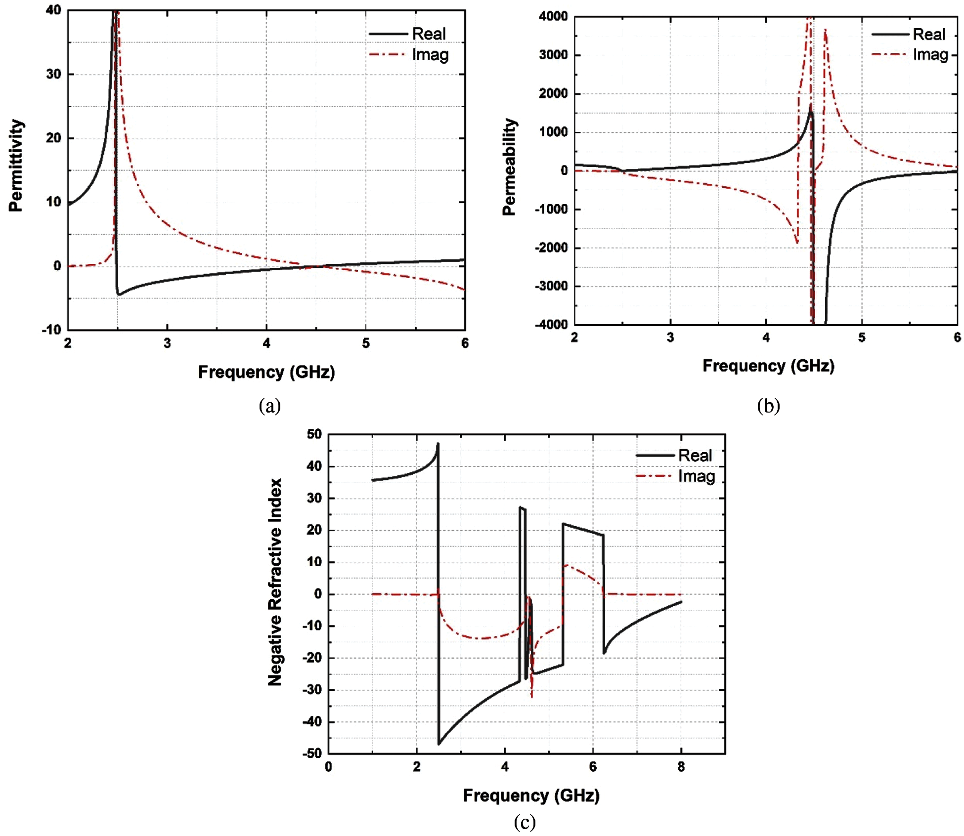
Figure 7: Effective constitutive parameters (a) permittivity, (b) permeability and (c) refractive index
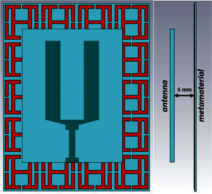
Figure 8: Antenna loaded with metamaterial
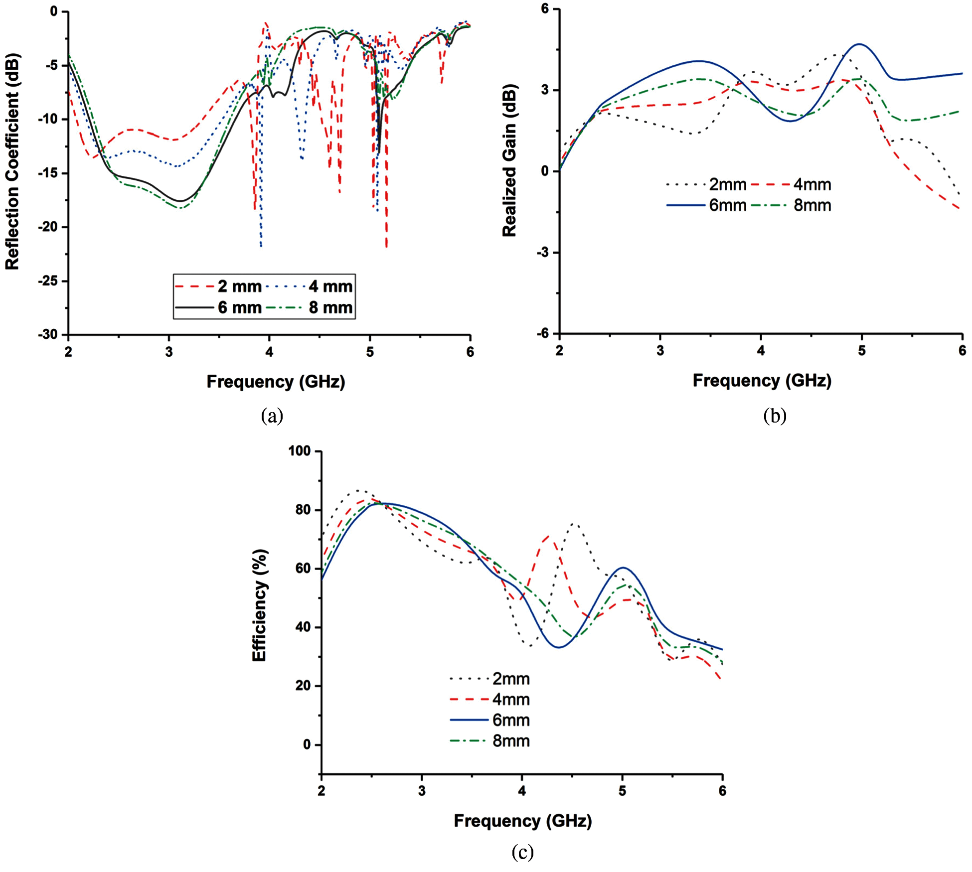
Figure 9: Antenna performances for different distances (a) reflection coefficient, (b) realized gain and (c) efficiency
The simulated and measured radiation patterns of the metamaterial loaded antenna at the frequencies of 2.4 and have been plotted in Fig. 12. Nearly omnidirectional radiation patterns for H-plane and Figure-eight shape radiation patterns in E-plane has been obtained. Moreover, a low cross-polarization level is observed for both E-plane and H-plane.
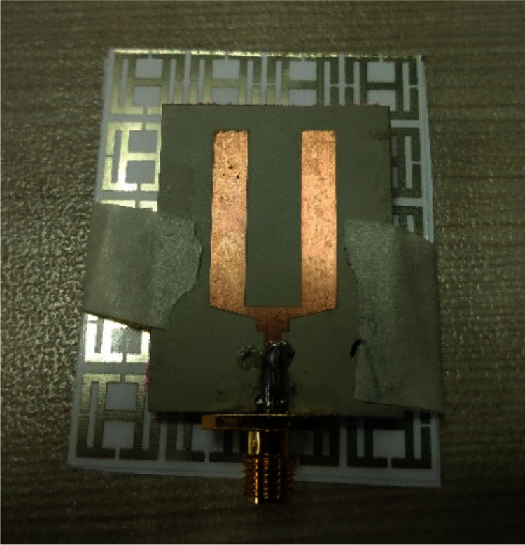
Figure 10: Photograph of metamaterial loaded antenna
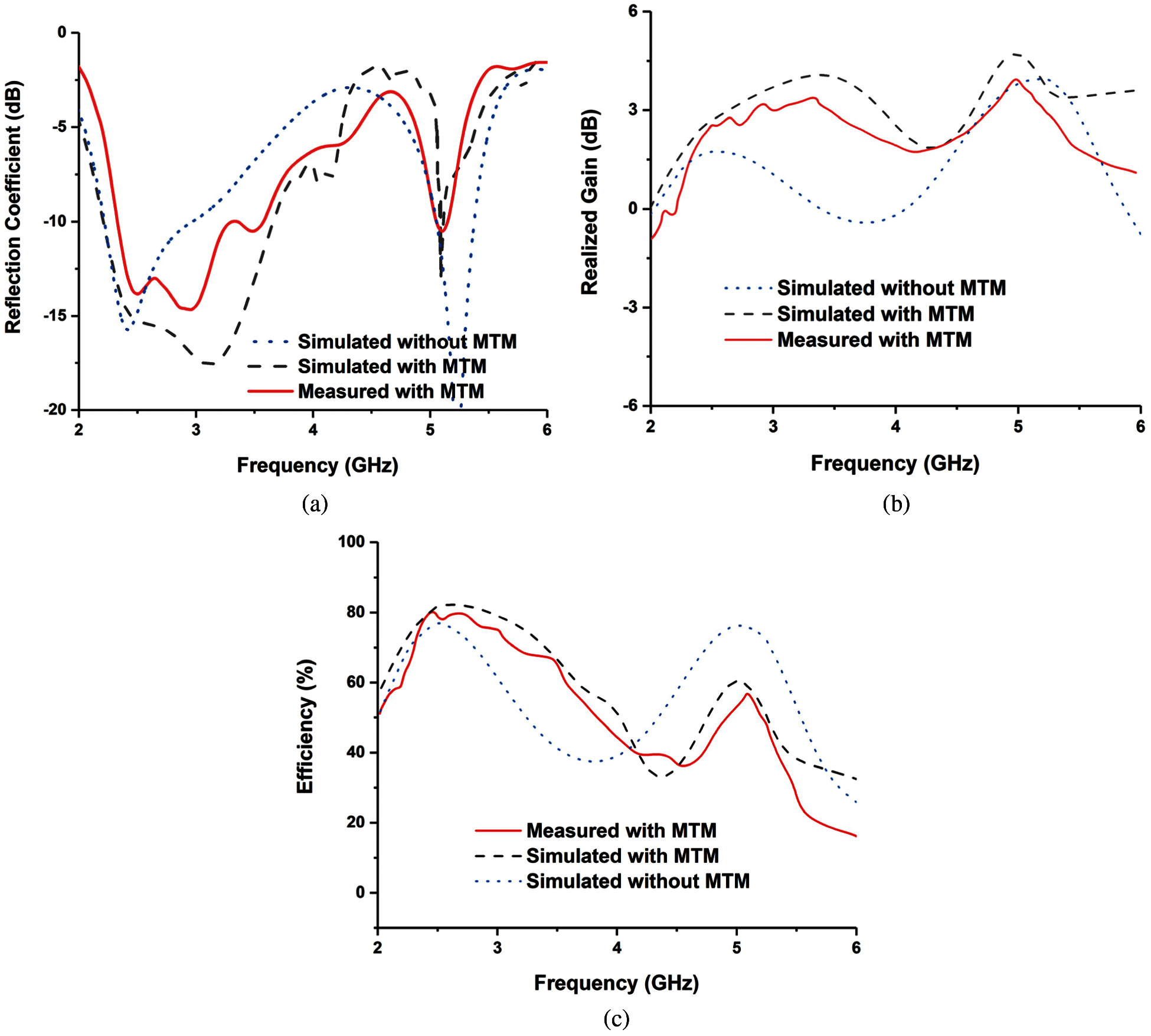
Figure 11: Metamaterial loaded antenna performances (a) reflection coefficient, (b) realized gain and (c) efficiency
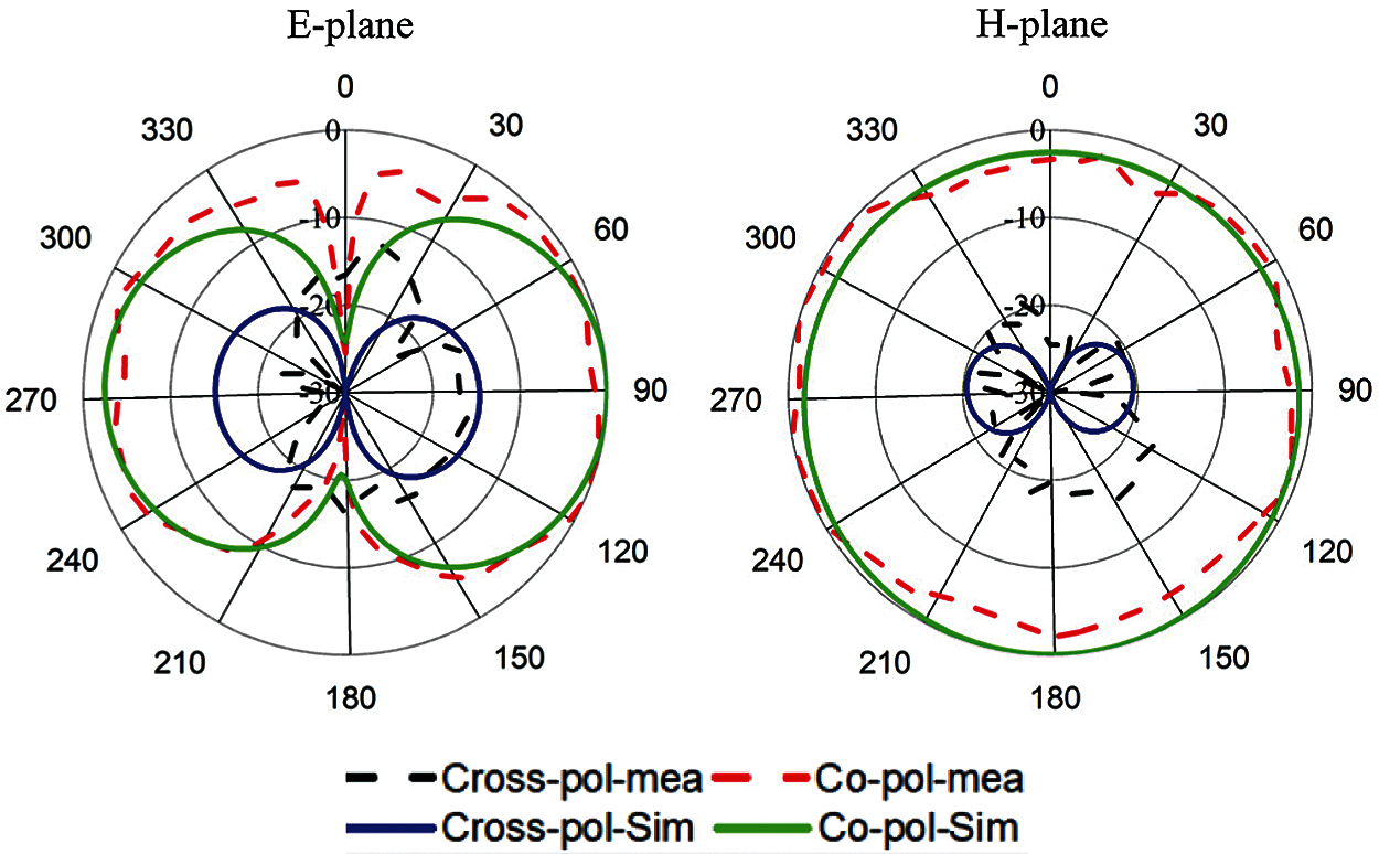
Figure 12: Radiation patterns of the metamaterial loaded antenna at 2.4 GHz
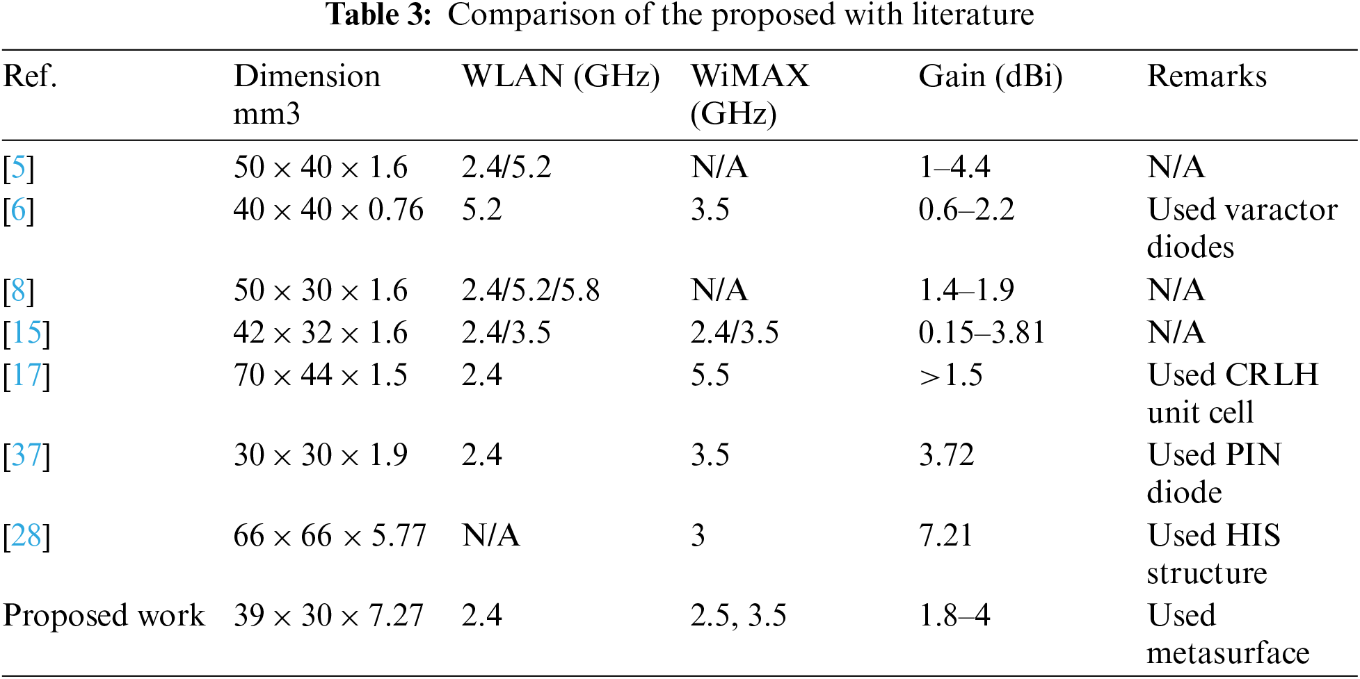
The performance comparison between the proposed work and other works in the literature is presented in Tab. 3. The proposed design has a compact dimension and shows comparatively better performance for both the WLAN and WiMAX bands than the antennas presented in the literature.
A simple, low-cost inkjet-printed quad split-ring resonator loaded antenna is proposed for WLAN and WiMAX applications. The metamaterial characteristics have been investigated in both simulation and measurement, where good agreement is found between the two results. Moreover, the presented metamaterial structure can enhance impedance bandwidth as well as realized gain at the resonant frequency. The measured results show that the realized gain of the metamaterial loaded antenna gets improved by more than 0.6 dBi within the operating band and the impedance bandwidth is increased from 0.75 to 1.25 GHz. The proposed metamaterial loaded antenna has good radiation characteristics with an omnidirectional radiation pattern, so it can emerge as an excellent candidate for WLAN/WiMAX wireless communication.
Funding Statement: This work is supported by Universiti Kebangsaan Malaysia research Grant No: DIP-2020-010.
Conflicts of Interest: The authors declare that they have no conflicts of interest to report regarding the present study.
1. J. Anguera, A. Andújar, M.-C. Huynh, C. Orlenius, C. Picher et al., “Advances in antenna technology for wireless handheld devices,” International Journal of Antennas and Propagation, vol. 2013, pp. 1–26, 2013. [Google Scholar]
2. R. Azim, T. Alam, M. S. Mia, A. F. Almutairi and M. T. Islam, “An octa-band planar monopole antenna for portable communication devices,” Scientific Reports, vol. 11, no. 1, pp. 1–13, 2021. [Google Scholar]
3. A. Ghaffar, W. A. Awan, N. Hussain and X.-J. Li, “A compact octa-band frequency reconfigurable antenna for wireless applications,” Mathematics, vol. 9, no. 13, pp. 1557, 2021. [Google Scholar]
4. M. Moosazadeh and S. Kharkovsky, “Compact and small planar monopole antenna with symmetrical L-and U-shaped slots for WLAN/WiMAX applications,” IEEE Antennas and Wireless Propagation Letters, vol. 13, pp. 388–391, 2014. [Google Scholar]
5. S. Ismail, S. Rahim, A. Ibrahim, M. Sabran and H. Mohamad, “Dual band inverted H-shaped slot monopole antenna for WLAN applications,” in 2015 IEEE 12th Malaysia Int. Conf. on Communications (MICCKuching, Malaysia, pp. 197–200, 2015. [Google Scholar]
6. A. Boukarkar, X. Q. Lin and Y. Jiang, “A dual-band frequency-tunable magnetic dipole antenna for WiMAX/WLAN applications,” IEEE Antennas and Wireless Propagation Letters, vol. 15, pp. 492–495, 2015. [Google Scholar]
7. Y. Cao, S. Cheung and T. Yuk, “A multiband slot antenna for GPS/WiMAX/WLAN systems,” IEEE Transactions on Antennas and Propagation, vol. 63, no. 3, pp. 952–958, 2015. [Google Scholar]
8. C. -Y. Huang and E. -Z. Yu, “A slot-monopole antenna for dual-band WLAN applications,” IEEE Antennas and Wireless Propagation Letters, vol. 10, pp. 500–502, 2011. [Google Scholar]
9. W. A. Awan, A. Ghaffar, N. Hussain and X. J. Li, “CPW-Fed dual-band antenna for 2.45/5.8 GHz applications,” in Pacific Conf. on Antennas and Propagation, Incheon, Korea (Southpp. 246–247, 2019. [Google Scholar]
10. D. D. Krishna, M. Gopikrishna, C. Anandan, P. Mohanan and K. Vasudevan, “CPW-Fed koch fractal slot antenna for WLAN/WiMAX applications,” IEEE Antennas and Wireless Propagation Letters, vol. 7, pp. 389–392, 2008. [Google Scholar]
11. L. C. Paul, M. S. Hosain, S. Sarker, M. H. Prio, M. Morshed and A. K. Sarkar, “The effect of changing substrate material and thickness on the performance of inset feed microstrip patch antenna,” American Journal of Networks and Communications, vol. 4, no. 3, pp. 54–58, 2015. [Google Scholar]
12. Y. Pan and S. Zheng, “A low-profile stacked dielectric resonator antenna with high-gain and wide bandwidth,” IEEE Antennas and Wireless Propagation Letters, vol. 15, pp. 68–71, 2016. [Google Scholar]
13. A. A. Khan, M. H. Jamaluddin, S. Aqeel, J. Nasir and O. Owais, “Dual-band MIMO dielectric resonator antenna for WiMAX/WLAN applications,” IET Microwaves, Antennas & Propagation, vol. 11, no. 1, pp. 113–120, 2017. [Google Scholar]
14. R. S. Daniel, R. Pandeeswari and S. Raghavan, “A compact metamaterial loaded monopole antenna with offset-fed microstrip line for wireless applications,” AEU-International Journal of Electronics and Communications, vol. 83, pp. 88–94, 2018. [Google Scholar]
15. M. M. Hasan, M. R. I. Faruque and M. T. Islam, “Dual band metamaterial antenna for LTE/bluetooth/WiMAX system,” Scientific Reports, vol. 8, no. 1, pp. 1–17, 2018. [Google Scholar]
16. R. S. Daniel, R. Pandeeswari and S. Raghavan, “Dual-band monopole antenna loaded with ELC metamaterial resonator for WiMAX and WLAN applications,” Applied Physics A, vol. 124, no. 8, pp. 570, 2018. [Google Scholar]
17. H. Li, Q. Zheng, J. Ding and C. Guo, “Dual-band planar antenna loaded with CRLH unit cell for WLAN/WiMAX application,” IET Microwaves, Antennas & Propagation, vol. 12, no. 1, pp. 132–136, 2017. [Google Scholar]
18. T. Ali and R. C. Biradar, “A miniaturized volkswagen logo UWB antenna with slotted ground structure and metamaterial for GPS, WiMAX and WLAN applications,” Progress in Electromagnetics Research, vol. 72, pp. 29–41, 2017. [Google Scholar]
19. D. R. Smith, W. J. Padilla, D. Vier, S. C. Nemat-Nasser and S. Schultz, “Composite medium with simultaneously negative permeability and permittivity,” Physical Review Letters, vol. 84, no. 18, pp. 4184, 2000. [Google Scholar]
20. F. Falcone, T. Lopetegi, J. D. Baena, R. Marqués, F. Martín et al., “Effective negative-/spl epsiv/stopband microstrip lines based on complementary split ring resonators,” IEEE Microwave and Wireless Components Letters, vol. 14, no. 6, pp. 280–282, 2004. [Google Scholar]
21. Y. Dong, H. Toyao and T. Itoh, “Design and characterization of miniaturized patch antennas loaded with complementary split-ring resonators,” IEEE Transactions on Antennas and Propagation, vol. 60, no. 2, pp. 772, 2012. [Google Scholar]
22. S. Basaran, U. Olgun and K. Sertel, “Multiband monopole antenna with complementary split-ring resonators for WLAN and WiMAX applications,” Electronics Letters, vol. 49, no. 10, pp. 636–638, 2013. [Google Scholar]
23. R. Pandeeswari and S. Raghavan, “Microstrip antenna with complementary split ring resonator loaded ground plane for gain enhancement,” Microwave and Optical Technology Letters, vol. 57, no. 2, pp. 292–296, 2015. [Google Scholar]
24. D. Sarkar, K. Saurav and K. V. Srivastava, “Multi-band microstrip-fed slot antenna loaded with split-ring resonator,” Electronics Letters, vol. 50, no. 21, pp. 1498–1500, 2014. [Google Scholar]
25. D. Gangwar, S. Das and R. Yadava, “Gain enhancement of microstrip patch antenna loaded with split ring resonator based relative permeability near zero as superstrate,” Wireless Personal Communications, vol. 96, no. 2, pp. 2389–2399, 2017. [Google Scholar]
26. M. Abdalla, M. Ghouz and M. A. El-Dahab, “Dual band new bisected-π CRLH metamaterial cell loaded dipole antennas,” Journal of Instrumentation, vol. 13, no. 6, pp. P06003, 2018. [Google Scholar]
27. L. -M. Si, Q. -L. Zhang, W. -D. Hu, W. -H. Yu, Y. -M. Wu et al., “A uniplanar triple-band dipole antenna using complementary capacitively loaded loop,” IEEE Antennas and Wireless Propagation Letters, vol. 14, pp. 743–746, 2015. [Google Scholar]
28. P. K. Panda and D. Ghosh, “Wideband and high gain tuning fork shaped monopole antenna using high impedance surface,” AEU-International Journal of Electronics and Communications, vol. 111, pp. 152920, 2019. [Google Scholar]
29. S. K. Mishra, R. K. Gupta, A. Vaidya and J. Mukherjee, “A compact dual-band fork-shaped monopole antenna for bluetooth and UWB applications,” IEEE Antennas and Wireless Propagation Letters, vol. 10, pp. 627–630, 2011. [Google Scholar]
30. B. S. Cook and A. Shamim, “Inkjet printing of novel wideband and high gain antennas on low-cost paper substrate,” IEEE Transactions on Antennas and Propagation, vol. 60, no. 9, pp. 4148–4156, 2012. [Google Scholar]
31. S. S. Islam, M. R. I. Faruque and M. T. Islam, “A new direct retrieval method of refractive index for the metamaterial,” Current Science (00113891), vol. 109, no. 2, pp. 337–342, 2015. [Google Scholar]
32. Z. Szabó, G.-H. Park, R. Hedge and E.-P. Li, “A unique extraction of metamaterial parameters based on kramers-kronig relationship,” IEEE Transactions on Microwave Theory and Techniques, vol. 58, no. 10, pp. 2646–2653, 2010. [Google Scholar]
33. U. C. Hasar, A. Muratoglu, M. Bute, J. J. Barroso and M. Ertugrul, “Effective constitutive parameters retrieval method for bianisotropic metamaterials using waveguide measurements,” IEEE Transactions on Microwave Theory and Techniques, vol. 65, no. 5, pp. 1488–1497, 2017. [Google Scholar]
34. X. Chen, T. M. Grzegorczyk, B.-I. Wu, J. Pacheco Jr. and J. A. Kong, “Robust method to retrieve the constitutive effective parameters of metamaterials,” Physical Review E, vol. 70, no. 1, pp. 016608, 2004. [Google Scholar]
35. E. J. Rothwell and R. O. Ouedraogo, “Antenna miniaturization: Definitions, concepts, and a review with emphasis on metamaterials,” Journal of Electromagnetic Waves and Applications, vol. 28, no. 17, pp. 2089–2123, 2014. [Google Scholar]
36. C. Milias, R. B. Andersen, P. I. Lazaridis, Z. D. Zaharis, B. Muhammad et al., “Metamaterial-inspired antennas: A review of the state of the art and future design challenges,” IEEE Access, vol. 9, pp. 89846–89865, 2021. [Google Scholar]
37. A. Ghaffar, X. J. Li, W. A. Abbas Awan, S. I. Iffat Naqvi, N. Hussain et al., “Design and realization of a frequency reconfigurable multimode antenna for ISM, 5G-Sub-6-GHz, and S-band applications,” Applied Sciences, vol. 11, no. 4, pp. 1635, 2021. [Google Scholar]
 | This work is licensed under a Creative Commons Attribution 4.0 International License, which permits unrestricted use, distribution, and reproduction in any medium, provided the original work is properly cited. |