DOI:10.32604/cmc.2022.021852
| Computers, Materials & Continua DOI:10.32604/cmc.2022.021852 | |
| Article |
Low Profile UHF Antenna Design for Low Earth-Observation CubeSats
1School of Electrical and Data Engineering, Faculty of Engineering and Information Technology, University of Technology Sydney, Ultimo NSW, 2007, Australia
2Space Science Centre (ANGKASA), Institute of Climate Change (IPI), Universiti Kebangsaan Malaysia, Bangi, 43600, Selangor, Malaysia
3Department of CSE, International Islamic University Chittagong (IIUC), Chattogram, 4318, Bangladesh
4Electrical Engineering Department, Kuwait University, 13060, KuwaitCity, Kuwait
5Department of Electrical, Electronic and Systems Engineering, Faculty of Engineering and Built Environment, Universiti Kebangsaan Malaysia, Bangi, 43600, Selangor, Malaysia
*Corresponding Author: Ali F. Almutairi. Email: ali.almut@ku.edu.kw
Received: 17 July 2021; Accepted: 03 September 2021
Abstract: This paper reveals a new design of UHF CubeSat antenna based on a modified Planar Inverted F Antenna (PIFA) for CubeSat communication. The design utilizes a CubeSat face as the ground plane. There is a gap of 5 mm beneath the radiating element that facilitates the design providing with space for solar panels. The prototype is fabricated using Aluminum metal sheet and measured. The antenna achieved resonance at 419 MHz. Response of the antenna has been investigated after placing a solar panel. Lossy properties of solar panels made the resonance shift about 20 MHz. This design addresses the frequency shifting issue after placing the antenna with the CubeSat body. This phenomenon has been analyzed considering a typical 1U and 2U CubeSat body with the antenna. The antenna achieved a positive realized gain of 0.7 dB and approximately 78% of efficiency at the resonant frequency with providing 85% of open space for solar irradiance onto the solar panel.
Keywords: CubeSat antenna; UHF antenna; small satellite; satellite communication
The development of the first CubeSat in the year of 2003 unfolded a new dimension for the space researchers’ community. Space exploration missions became open for private and government organizations while attracting the research interest of universities [1–4]. Moreover, CubeSats are allowing developing countries to get the touch of aerospace with less expense considering the basic features of CubeSats such as low manufacturing cost, simpler design, small development duration. Moreover, CubeSats are often built with off-the-shelf components that are available commercially; the upshot, CubeSats have enabled satellite researchers for bigger mission with minimal cost [5]. Acceptance of CubeSats among researchers is increasing throughout the last five years [6]. The communication system is vital in any CubeSat since it maintains connectivity with the ground station. Antenna is one of the most important elements in any communication system. Since more than one antenna is needed in CubeSats, different antennas operating at individual frequencies are placed around the satellite body ensuring that one antenna does not affect other antenna’s performance [7]. Generally, CubeSats are launched in space using special deplorers. So, stringent requirements for weight, power, and geometry need to be followed and these three (weight, power, and geometry) are the crucial consideration issues that have a great impact on desining antenna system. Researchers are emphasizing new antenna designs that can cover the CubeSat requisites as well as maintain the performance of the antenna. Different types of antennas including patch, horn, refectory, membrane, reflector, wire etc. are reported in literature for Cu-beSat application [8–10]. Dipoles, monopoles, Yagi–Uda arrays, and helical antennas are several types of wire antenna. The adverse fact of using wire antennas in CubeSats is, they are required to be deployed mechanically [5,11–13]. So, there is always a chance of mission failure due to improper and sophisticated deployment mechanisms, which increase mission complexity. Printed patch antennas are more convenient alternative of conventional wire antennas where deployable antennas increase mission complexity. In contrast to the deployable antenna, the Patch antenna provides low profile. However, patch antenna with partial ground plane has strong affect on metallic CubeSat structure [14]. Moreover, obtaining lower UHF operating band is a challenge due to design limitations. In addition, patch antennas are mounted on the CubeSat face that can be used for the placement of solar panels instead. Good radiation characteristics is achievable using horn antennas, but the downside, they are large in size and more suitable in higher frequency operation. In [15–17], planar inverted-F antennas (PIFA) have been proposed for the CubeSat communication system.
In this paper, the design structure of a modified PIFA for UHF CubeSat communication has been revealed that can pave the way to address the shortcomings of deployable and patch antennas for the CubeSat mission. One of the faces of the typical CubeSat body is taken as the ground plane of the antenna. The design facilitates open space that can enable solar irradiance to pass through the slot of the radiating element. Design and simulation processes are performed in CST (Computer Simulation Technology) Microwave Studio. The design is simulated using 0.2 mm thick Aluminum material while the thickness of the ground plane is 0.5 mm. Finally, it has been fabricated with Aluminum sheet. The antenna performance is measured using PNA Network Analyzer. The proposed antenna resonates at 419 MHz in free space. The performance of the antenna has also been investigated with solar panels and while the antenna mounted with CubeSat backplane.
The perspective view of the proposed Planar Inverted F Antenna (PIFA) is shown in Fig. 1a. The main radiating section is designed to deliver a larger effective length to realize resonance at desired UHF band. The rectangular shaped element at the corner has great significance in achieving resonance at 419 MHz. The width of the strip-type radiating element is 5 mm. The whole PIFA is designed using 0.2 mm Aluminum sheet. The resonant frequency can roughly be estimated by Eq. (1) [18].
where, c is the velocity of light, b is the width of the radiating element and L is the effective length of the radiating element. Space in-between the ground plane and upper radiating structure is 5 mm. There is a gap named ‘h’ is maintained between the edge of the ground plane and the edge of radiating structure that facilitates the antenna to adjust on the CubeSat frame. There is a 2 mm distance between the feed point and the shorting wall. Parametric study on W1 and L2 has been performed to obtain the optimized design parameters of the antenna. Fig. 2 depicts the results of the parametric study. L2 has a significant impact on the resonant frequency, it can also be used to tune the antenna. Moreover, conventional shorting wall techniques is utilized to achieve lower resonance frequency and enhanced reflection coefficient. The optimization of the design parameters is performed in numerical simulation, optimized parameters as included in Tab. 1.
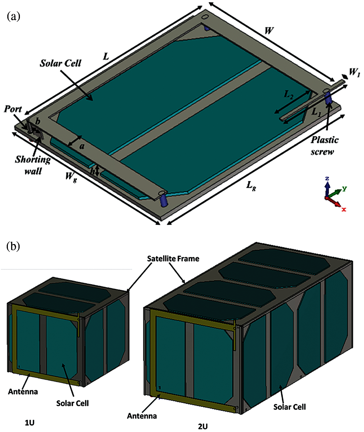
Figure 1: (a) Design configuration of the proposed antenna, (b) Antenna mounted with typical CubeSat body
The radiating element of the antenna has been fabricated from commercially available 0.2 mm Aluminium (Aluminium 7075) sheet where Aluminum of 0.5 mm thickness is used to form the ground plane. The principal radiating element is shaped according to the basic design and the shorting wall is bent at its respective place. Finally, an SMA connector is soldered with the ground plane and the feed point. The possible placement of the solar panel and placement of the antenna with the CubeSat body is shown in Fig. 1b. In the simulation, Gallium Arsenide based solar panels was considered, where the dielectric constant, heat capacity and thermal conductivity was 12.94, 0.33 kJ/K/kg and 54 W/K/m, respectively. Then the performance of the antenna is investigated while the antenna is mounted with a typical 1U and 2U CubeSat.
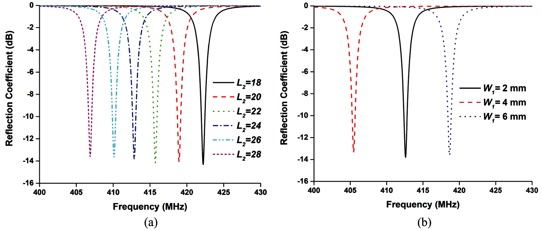
Figure 2: Reflection coefficient of the antenna for (a) L2 and (b) W1
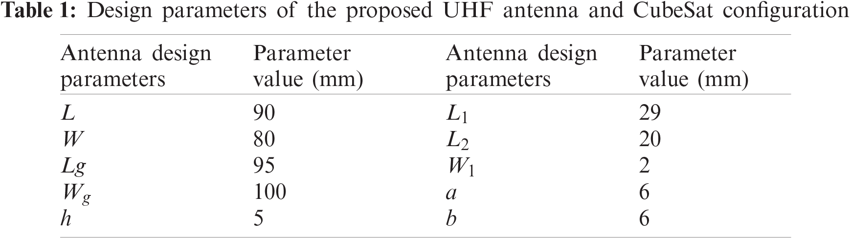
Fig. 3a illustrates the reflection coefficient of the antenna at different conditions. The reflection coefficient of the antenna has been investigated while the antenna in free space, mounted with solar panel and mounted with both solar panel and CubeSat body. It is seen that the resonant frequency shifts as the subsystems are mounted with the antenna. The surface current distribution of the proposed antenna with solar cell is depicted in Fig. 3b, where the surface current is evenly distributed in L and W. It is also shown that significant amount of current is flowing through L2 and W1, which is responsible for shifting resonance. The fabricated prototype of the proposed antenna mounted with solar panel is shown in Fig. 4.
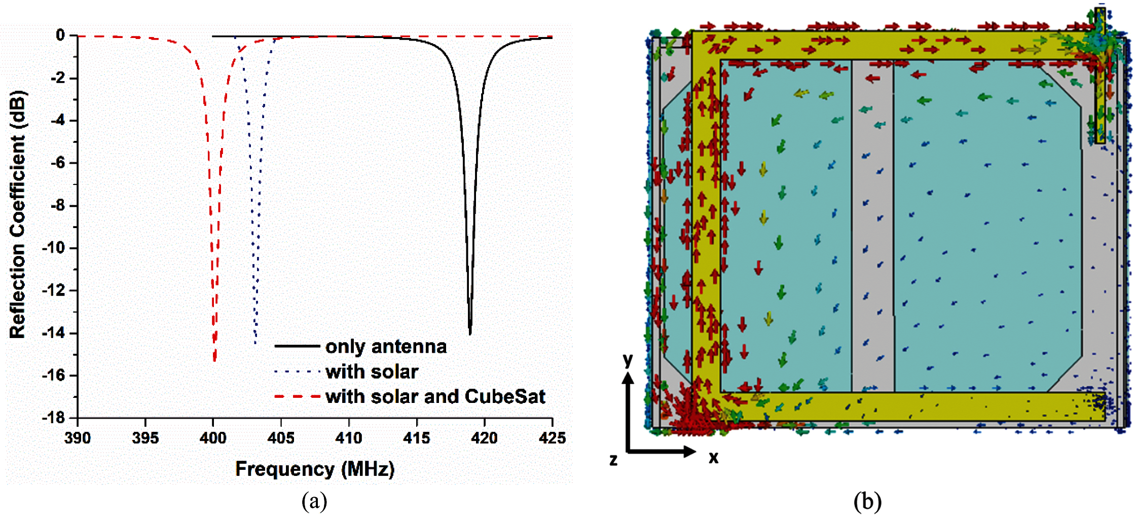
Figure 3: (a) Simulated reflection coefficients of the antenna and (b) surface current distribution at 400 MHz
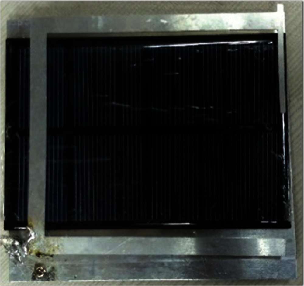
Figure 4: Fabricated prototypes of the antenna with solar panel
The Fig. 5a depicts the reflection coefficient of the solar panel mounted antenna. Fig. 5b represents the reflection coefficient of the antenna mounted with the CubeSat body and solar panel. Good agreement has been achieved between simulated and measured results. The measured results are found in good alignment with the simulated results. A slight mismatch can be noticed due to fabrication tolerance, SMA connector and the RF cable that facilitates the connection with VNA, which were not considered in simulation.
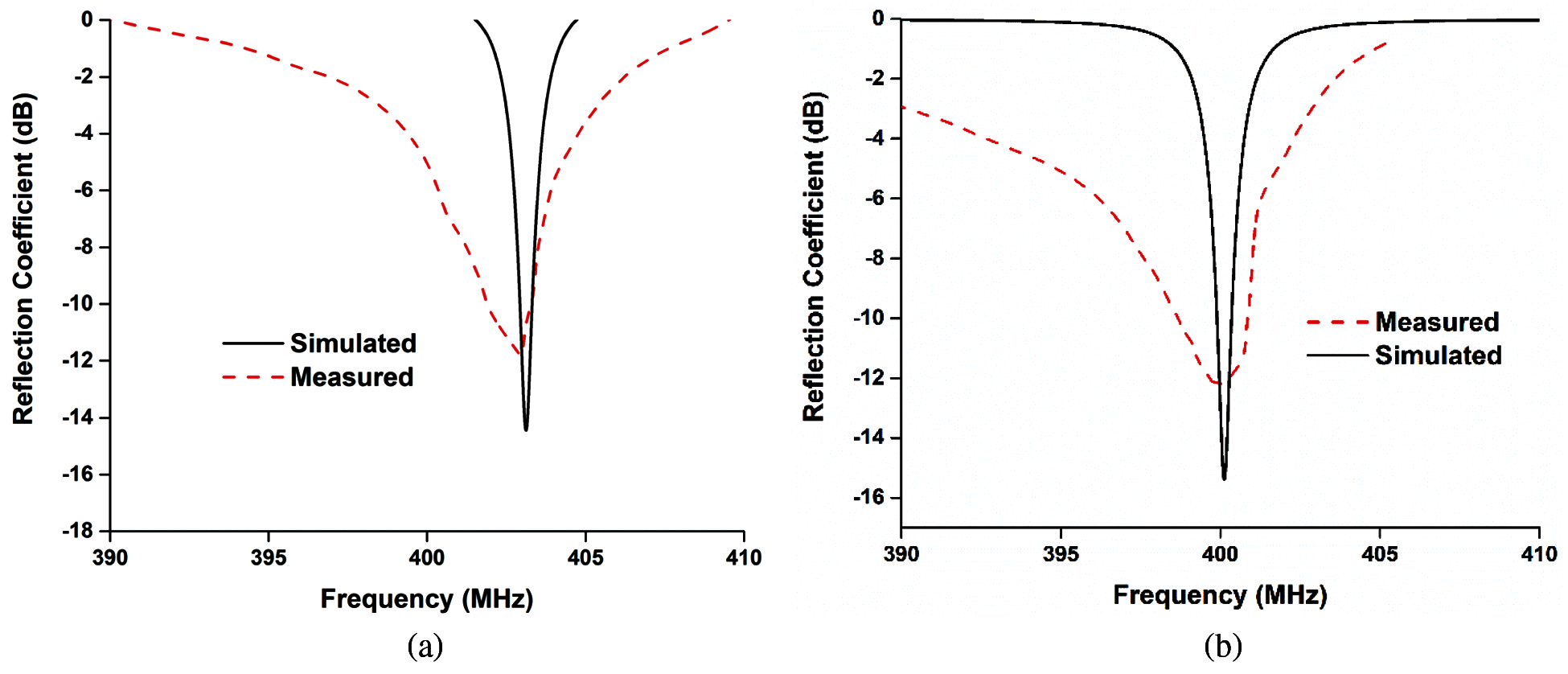
Figure 5: Reflection coefficients (a) with solar panel; (b) with solar panel and CubeSat
Performance of the antenna fluctuates due to the interaction between the lossy solar panel and radiating element of the antenna mounted on the body [19]. The antenna has been simulated and measured with solar panel to evaluate how the performance deviates. It is notable that, a significant frequency shift occurs because of the existence of solar panel. Nanosatellite patch antennas usually suffer from frequency shifting issues when they are mounted with the body. So, the reflection coefficient of the antenna mounted with nanosatellite body and solar panel has been investigated. It turned out that, the antenna’s operating frequency remained stable when it is mounted with the nanosatellite body.
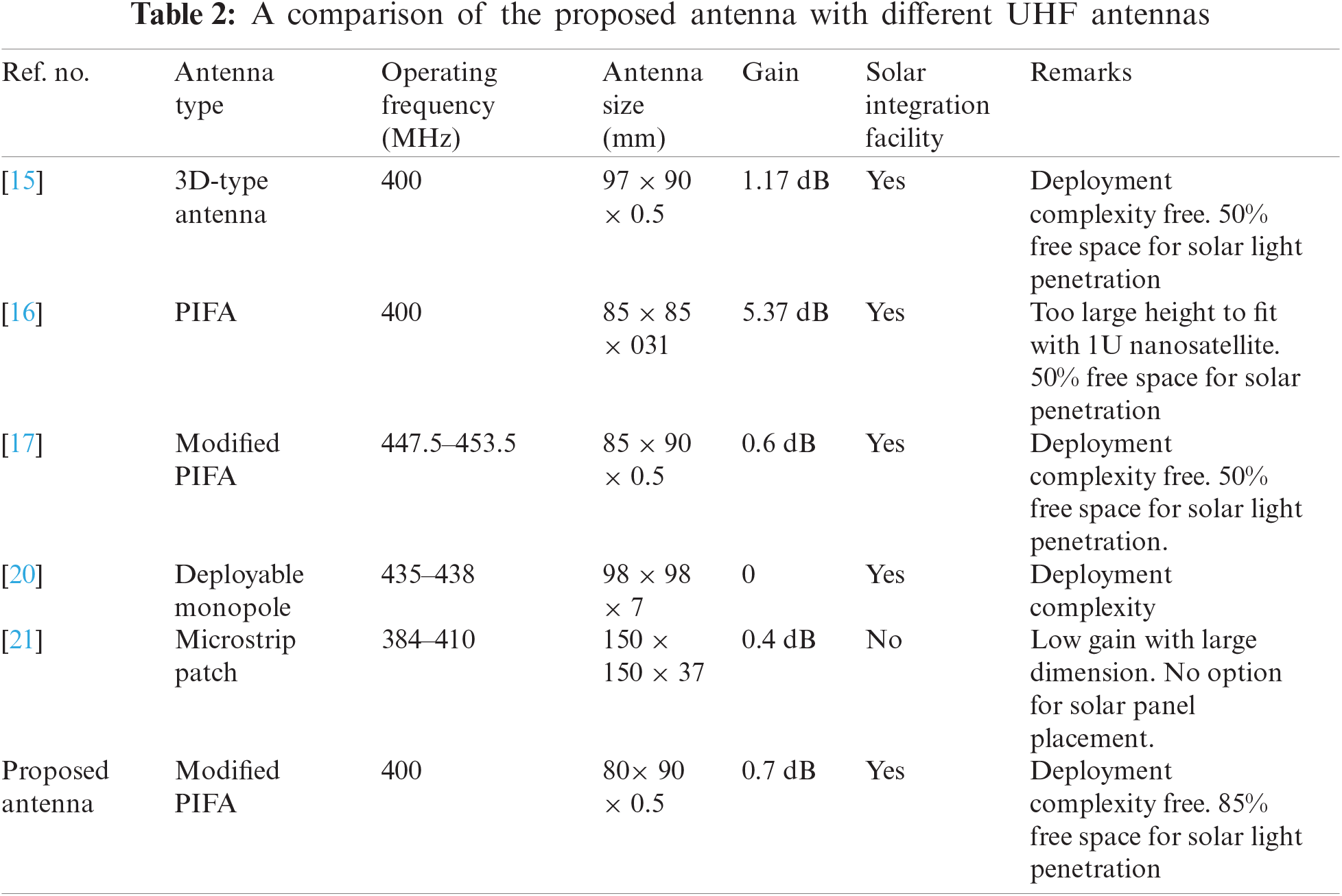
Radiation patterns of the antenna have been presented in Fig. 6. The radiation patterns remained stable even after mounting the antenna with the CubeSat structure with satisfactory beamwidth to maintain communication from LEO, shown in Fig. 7. Investigation of the radiation efficiency while the antenna is mounted with solar panel has also been performed. Up to 78% efficiency is found while the antenna is mounted with solar panel with up to 0.7 dB realized gain depicted in Fig. 8. A comparison among the proposed antenna, commercial antennas [20] and some other existing small satellite antennas is presented in Tab. 2. Based on the comparison, the proposed PIFA antenna provides 0.7 dB of gain at 400 MHz with retaining lower UHF antenna design constraints. So, the proposed antenna shows potentiality for smooth Low Earth-Observation CubeSats operation.
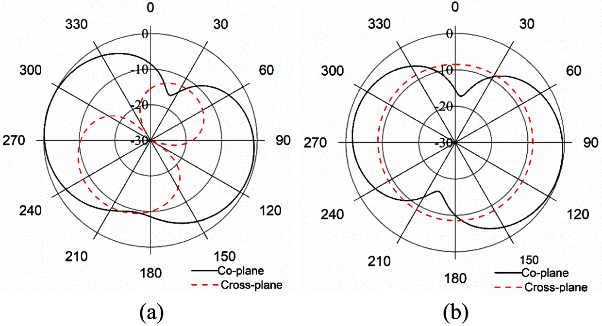
Figure 6: Radiation pattern of the antenna (a) at xz; (b) at yz plane
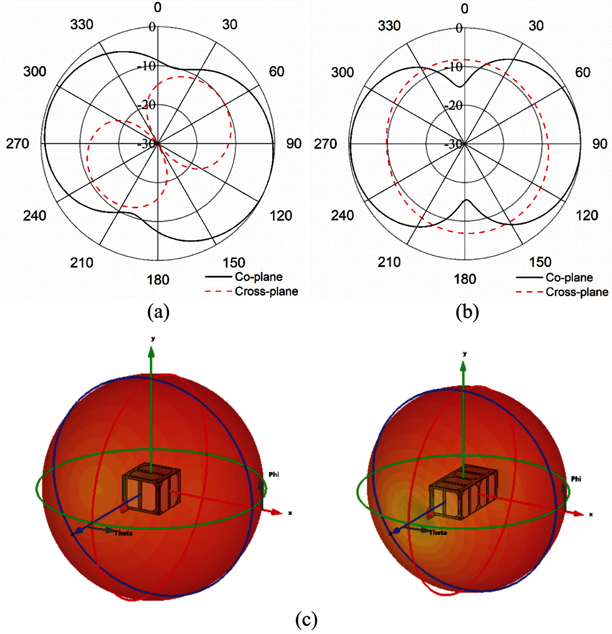
Figure 7: Radiation patterns of the antenna (mounted with CubeSat body) (a) at xz; (b) at yz plane and (c) 3D radiation pattern with 1U and 2U CubeSats
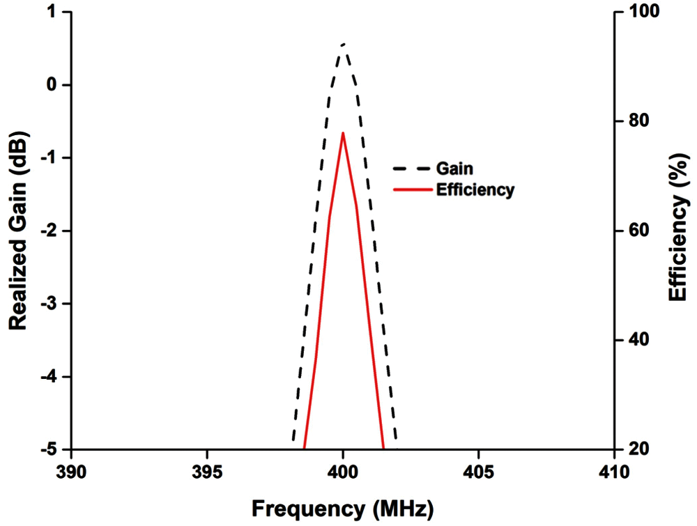
Figure 8: Realized gain and efficiency of the proposed UHF antenna
This paper presents a new design approach of a modified PIFA antenna for CubeSat communication in the UHF band. The antenna operates at UHF frequency while it serves the facility of solar panel integration between the ground plane and radiating element and provides 85% free space for solar light penetration. The antenna prototype has been fabricated using Aluminum sheet. The effect of placing solar panels and CubeSat body with the antenna have been investigated in this study which is the potential for satellite communication.
Acknowledgement: The authors acknowledge the technical support with thanks to Universiti Kebangsaan Malaysia.
Funding Statement: The authors received no specific funding for this study.
Conflicts of Interest: The authors declare that they have no conflicts of interest to report regarding the present study.
1. E. Peral, E. Im, L. Wye, S. Lee, S. Tanelli et al., “Radar technologies for earth remote sensing from cubesat platforms,” Proceedings of the IEEE, vol. 106, no. 3, pp. 404–418, 2018. [Google Scholar]
2. N. Saeed, A. Elzanaty, H. Almorad, H. Dahrouj, T. Y. Al-Naffouri et al., “Cubesat communications: Recent advances and future challenges,” IEEE Communications Surveys & Tutorials, vol. 22, no. 3, pp. 1839–1862, 2020. [Google Scholar]
3. A. M. Junqueira, F. Mao, T. S. Mendes, S. J. Simões, J. A. Balestieri et al., “Estimation of river flow using cubesats remote sensing,” Science of the Total Environment, vol. 788, no. 2, pp. 147762, 2021. [Google Scholar]
4. C. Nieto-Peroy and M. R. Emami, “CubeSat mission: From design to operation,” Applied Sciences, vol. 9, no. 15, pp. 3110, 2019. [Google Scholar]
5. J. Costantine, Y. Tawk, I. Maqueda, M. Sakovsky, G. Olson et al., “UHF deployable helical antennas for cubesats,” IEEE Transactions on Antennas and Propagation, vol. 64, no. 9, pp. 3752–3759, 2016. [Google Scholar]
6. Sluspacelab, “Flight missions,” 2020. [Online]. Available: https://www.sluspacelab.com/flight-missions. [Google Scholar]
7. Y. Yao, S. Liao, J. Wang, K. Xue, E. A. Balfour et al., “A new patch antenna designed for cubesat: Dual feed, L/S dual-band stacked, and circularly polarized,” IEEE Antennas and Propagation Magazine, vol. 58, no. 3, pp. 16–21, 2016. [Google Scholar]
8. T. Yasin and R. Baktur, “Circularly polarized meshed patch antenna for small satellite application,” IEEE Antennas and Wireless Propagation Letters, vol. 12, pp. 1057–1060, 2013. [Google Scholar]
9. K. S. Sadasivan, S. N. Shalini, B. S. Cheela and N. Annavarapu, “Design and analysis of antennas for a nano-satellite,” in IEEE Aerospace Conf., Big Sky, MT, USA, pp. 1–9, 2017. [Google Scholar]
10. A. Nascetti, E. Pittella, P. Teofilatto and S. Pisa, “High-gain S-band patch antenna system for earth-observation cubesat satellites,” IEEE Antennas and Wireless Propagation Letters, vol. 14, pp. 434–437, 2014. [Google Scholar]
11. X. Liu, J. Liu, D. R. Jackson, J. Chen, P. W. Fink et al., “Broadband transparent circularly-polarized microstrip antennas for cubesats,” in IEEE Int. Symp. on Antennas and Propagation (APSURSILas Croabas, Puerto Rico, pp. 1545–1546, 2016. [Google Scholar]
12. N. Chahat, R. E. Hodges, J. Sauder, M. Thomson, E. Peral et al., “Cubesat deployable Ka-band mesh reflector antenna development for earth science missions,” IEEE Transactions on Antennas and Propagation, vol. 64, no. 6, pp. 2083–2093, 2016. [Google Scholar]
13. N. Chahat, R. E. Hodges, J. Sauder, M. Thomson and Y. Rahmat-Samii, “The deep-space network telecommunication cubesat antenna: Using the deployable Ka-band mesh reflector antenna,” IEEE Antennas and Propagation Magazine, vol. 59, no. 2, pp. 31–38, 2017. [Google Scholar]
14. T. Alam, A. F. Almutairi, M. Samsuzzaman, M. Cho and M. T. Islam, “Metamaterial array based meander line planar antenna for cube satellite communication,” Scientific Reports, vol. 11, no. 1, pp. 1–12, 2021. [Google Scholar]
15. T. Alam, M. T. Islam, M. A. Ullah, R. Rahmatillah, K. Aheieva et al., “Design and compatibility analysis of a solar panel integrated UHF antenna for nanosatellite space mission,” PLOS ONE, vol. 13, no. 11, pp. e0205587, 2018. [Google Scholar]
16. H. Hu, W. Liao, L. Hou, F. Sun, G. Zhang et al., “Compact planar inverted-F antenna for microsats omnidirectional communications,” IEEE Antennas and Wireless Propagation Letters, vol. 20, no. 2, pp. 160–164, 2020. [Google Scholar]
17. T. Alam, M. T. Islam, M. Ullah and M. Cho, “A solar panel-integrated modified planner inverted F antenna for low earth orbit remote sensing nanosatellite communication system,” Sensors, vol. 18, no. 8, pp. 2480, 2018. [Google Scholar]
18. T. Taga and K. Tsunekawa, “Performance analysis of a built-in planar inverted F antenna for 800 MHz band portable radio units,” IEEE Journal on Selected Areas in Communications, vol. 5, no. 5, pp. 921–929, 1987. [Google Scholar]
19. T. Yekan and R. Baktur, “Conformal integrated solar panel antennas: Two effective integration methods of antennas with solar cells,” IEEE Antennas and Propagation Magazine, vol. 59, no. 2, pp. 69–78, 2017. [Google Scholar]
20. ISIS, “Innovative solutions in space,” 2020. [Online]. Available: https://www.isispace.nl/building-blocks/cubesat-subsystems/. [Google Scholar]
21. S. K. Podilchak, A. P. Murdoch and Y. M. Antar, “Compact, microstrip-based folded-shorted patches: PCB antennas for use on microsatellites,” IEEE Antennas and Propagation Magazine, vol. 59, no. 2, pp. 88–95, 2017. [Google Scholar]
 | This work is licensed under a Creative Commons Attribution 4.0 International License, which permits unrestricted use, distribution, and reproduction in any medium, provided the original work is properly cited. |