DOI:10.32604/cmc.2022.022436
| Computers, Materials & Continua DOI:10.32604/cmc.2022.022436 | |
| Article |
Proposed Different Signal Processing Tools for Efficient Optical Wireless Communications
1Department of Electronics and Communications Engineering, Faculty of Engineering, Zagazig University, Zagazig, 44519, Egypt
2Department of Information Technology, College of Computer and Information Sciences, Princess Nourah Bint Abdulrahman University, Riyadh, Saudi Arabia
3Department of Electronics and Electrical Communications Engineering, Faculty of Electronic Engineering, Menoufia University, Menoufia, 32952, Egypt
4 Security Engineering Lab, Computer Science Department, Prince Sultan University, Riyadh 11586, Saudi Arabia
*Corresponding Author: Abeer D. Algarni. Email: adalqarni@pnu.edu.sa
Received: 07 August 2021; Accepted: 22 September 2021
Abstract: Optical Wireless Communication (OWC) is a new trend in communication systems to achieve large bandwidth, high bit rate, high security, fast deployment, and low cost. The basic idea of the OWC is to transmit data on unguided media with light. This system requires multi-carrier modulation such as Orthogonal Frequency Division Multiplexing (OFDM). This paper studies optical OFDM performance based on Intensity Modulation with Direct Detection (IM/DD) system. This system requires a non-negativity constraint. The paper presents a framework for wireless optical OFDM system that comprises (IM/DD) with different forms, Direct Current biased Optical OFDM (DCO-OFDM), Asymmetrically Clipped Optical OFDM (ACO-OFDM), Asymmetrically DC-biased Optical OFDM (ADO-OFDM), and Flip-OFDM. It also considers channel coding as a tool for error control, channel equalization for reducing deterioration due to channel effects, and investigation of the turbulence effects. The evaluation results of the proposed framework reveal enhancement of performance. The performance of the IM/DD-OFDM system is investigated over different channel models such as AWGN, log-normal turbulence channel model, and ceiling bounce channel model. The simulation results show that the BER performance of the IM/DD-OFDM communication system is enhanced while the fading strength is decreased. The results reveal also that Hamming codes, BCH codes, and convolutional codes achieve better BER performance. Also, two algorithms of channel estimation and equalization are considered and compared. These algorithms include the Least Squares (LS) and the Minimum Mean Square Error (MMSE). The simulation results show that the MMSE algorithm gives better BER performance than the LS algorithm.
Keywords: Optical communication systems; OWC; IM/DD; OFDM; MMSE; LS; ADO-OFDM; DCO-OFDM; ACO-OFDM
Optical Wireless Communication (OWC) requires lightwave carriers such as Infra-Red (IR), visible, and Ultra-Violet (UV) light for transmitting data through unguided propagation media. Many ancient cultures use smoke, beacon fires, ship flags, and semaphore telegraph for signaling as examples of historical OWC [1]. Also, sunlight was used in the past as a form of OWC. For example, ancient Greeks and Romans use the reflected sunlight on their polished shields to send information signals during their battles. In the late 19th and early 20th centuries, a heliograph was invented and developed for military communication purposes. A heliograph consists of a pair of mirrors, which reflect the incident light beam to a long distance [2]. In 1880, Alexander Graham Bell invented another historical form of the OWC system: the photophone. He used the light source to modulate the received voice signals and transmit these voice signals to a distance of 200 m long [3]. In 1979, Gfeller and Bapst were able to achieve a fast advancement in OWC technology. They proved the ability of OWC for high-capacity in indoor networks providing an electromagnetic spectrum with hundreds of THz bandwidths in the optical domain [4].
The objective of any modern communication system is to provide high data rates and a wide range of services such as videophones, voice communications, and high-speed Internet access. Orthogonal Frequency Division Multiplexing (OFDM) is an attractive Multi-Carrier Modulation (MCM) technique that efficiently utilizes the available bandwidth. The OFDM systems can transmit high-speed data transmission across a noisy channel and combat multipath propagation effects. So, it is used in many applications such as Digital Audio Broadcasting (DAB) and Terrestrial Digital Video Broadcasting (DVB-T). It is also used in some of the most prominent wireless technologies, such as the IEEE 802.11 Wireless Local Area Networks (WLANs) and Long Term Evolution (LTE) technology [5–8].
Recently, OFDM has been applied to optical communication for supporting high data rates. However, the conventional OFDM technique cannot be directly used in optical systems. In OWC systems, the IM/DD technique is a simple, common, and low-cost optical carrier modulation and demodulation technique. In general, it is known that the output of the conventional OFDM modulator is complex and bipolar. In optical systems, only the intensity of the signal is constrained to be real and positive. Therefore, as commonly used in RF communication systems, the conventional OFDM must be modified to be used in OWC systems. Many existing OFDM modulation techniques are suitable for IM/DD OWC systems, such as ACO-OFDM, DCO-OFDM, ADO-OFDM, and Flip-OFDM. These four OFDM-based schemes are discussed in this work.
The rest of the work is organized as follows. Section 2 describes the intensity modulation direct detection (IM/DD) optical wireless communication system architecture. The general IM/DD system is described in Section 3. The channel coding method to improve the BER performance of any communication system is introduced in Section 4. Section 5 illustrates the proposed system models. Simulation results and discussions are given in Section 6. Finally, conclusions are given in Section 7.
2 IM/DD-OWC System Architecture
Fig. 1 shows the IM/DD-OWC system [9,10]. For OWC systems, an LED or an LD can be used as the optical transmitter for the intensity modulation process to convert the signal from the electrical domain to the optical domain (E/O). At the receiver, a photodiode can be used as the optical receiver for the direct detection process that can convert the signal from the optical domain to the electrical domain (O/E). The shot noise of the detector is added to the signal in the electrical domain, and it is represented by an Additive White Gaussian Noise (AWGN).
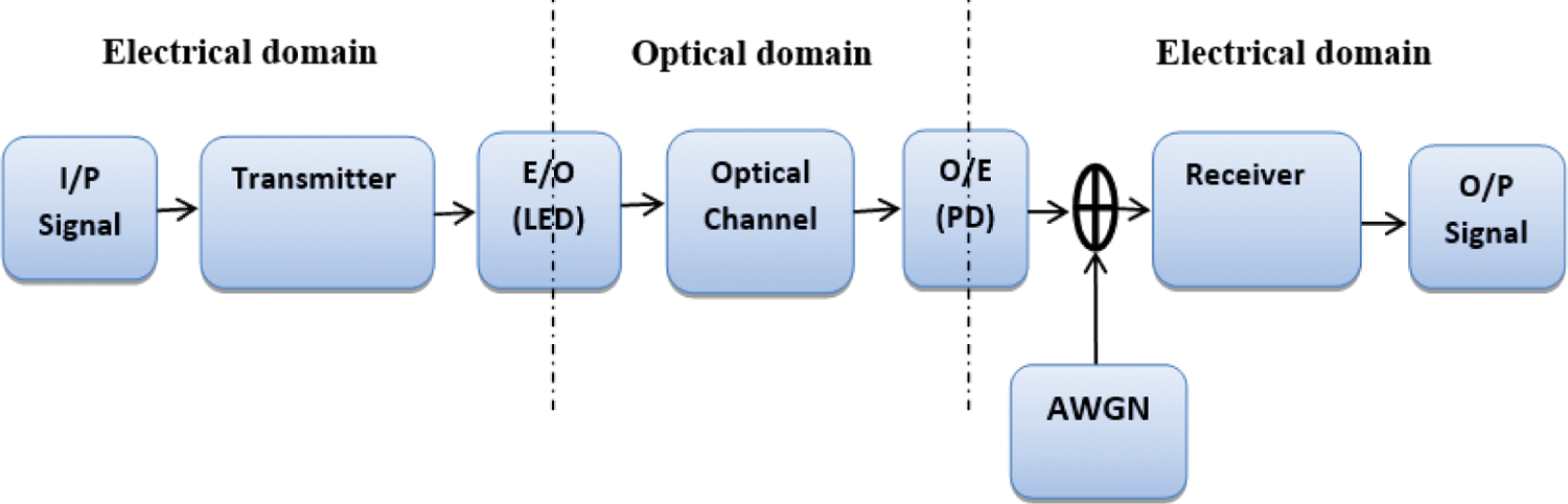
Figure 1: The IM/DD-OWC system
In the DCO-OFDM system, data symbols are carried on all sub-carriers [11,12]. In the DCO-OFDM transmitter, the serial input data is converted from Serial-to-Parallel (S/P), and then the data is mapped onto complex numbers using QAM or QPSK modulation. Then, the Hermitian symmetry property is applied to the symbols before the IFFT to get a real signal from the IFFT output [13]. This symmetry can be achieved by putting:
To prevent any residual DC component or any DC shift in the signal, X0, XN/2 are set to zero and do not carry any information [14], i.e.,
where N is the IFFT size, X is the complex symbol, and X* is the complex conjugate of the X symbol.
In the case of using a large number of sub-carriers N, the OFDM amplitude signal can be approximated by a Gaussian distribution with zero mean and a variance δD2 defined as,
The DC bias level is chosen to be proportional to the root mean square (RMS) of the signal to minimize the amount of required optical power and avoid increasing DC bias [15], i.e.,
where BDC is the DC bias level, μ is the proportionality constant, and δD is the root mean square of the electric power signal. After adding the DC bias BDC, the signal becomes
Any remaining negative peaks of xDC(t) signal are clipped at zero resulting in a clipping noise nc(BDC). The resulting unipolar DCO-OFDM signal xDCO(t) is expressed as
The ACO-OFDM technique has been explained in detail in many papers [16,17]. In ACO-OFDM, the data symbols are carried on the odd sub-carriers only, while the even sub-carriers form a bias signal, which guarantees that the transmitted OFDM signal achieves the non-negativity requirements. The bipolar OFDM signal is clipped at zero levels, where all negative parts of the bipolar signal are removed. Due to the clipping process, all of the noise components fall on the even sub-carriers, and the transmitted data is transmitted on the odd sub-carriers without impairments.
In the ACO-OFDM system, the front-end of the ACO-OFDM transmitter is like the DCO-OFDM transmitter, where the output of the IFFT is first converted from P/S, and the CP is appended to it [17]. Then, the resulting signal is D/A converted and low-pass filtered. The signal should be clipped at zero to ensure that the transmitted signal is positive. The LED can be used as an electrical to optical converter. The resulting optical signal is transmitted through an optical channel. Shot noise that affects the signal is modeled as AWGN and added in the electrical domain.
The processing in the ACO-OFDM receiver is similar to that of the DCO-OFDM receiver, except that in the ACO-OFDM receiver, only odd sub-carriers that carry data are demodulated, but in DCO-OFDM, all sub-carriers are demodulated.
The ADO-OFDM considers an advanced technique that maintains the advantages and avoids the drawbacks of the two previous optical unipolar OFDM techniques. The ADO-OFDM is a hybrid structure of ACO-OFDM and DCO-OFDM, where a DC bias is added to a part of the signal and the other part of the signal is clipped at zero. Thus, ACO-OFDM symbols modulate odd sub-carriers, while DCO-OFDM symbols modulate even sub-carriers. After that, the negative values produced by ACO-OFDM and DCO-OFDM are separately clipped to zero. Then, the resultant two non-negative signals from ACO-OFDM and DCO-OFDM are added together and transmitted by a LED [18].
The concept of Flip-OFDM is inverting the polarity of the negative part of the signal. The output of the IFFT operation is a real bipolar signal that can be decomposed into [19,20]:
where x+(k) and x−(k) are positive and negative parts of a bipolar signal, respectively. They are given as [19]:
where k = 0, 1, 2, …, N − 1. These two components of the signal are separately transmitted over two successive OFDM symbols. The positive part of the signal x+(k) is transmitted in the first sub-frame (positive sub-frame), while the Flipped part –x−(k) is transmitted in the second sub-frame (negative sub-frame). After that, a cyclic prefix with length NCP is added to each OFDM sub-frame. The negative OFDM sub-frame is delayed by (N + NCP) and transmitted after the positive OFDM sub-frame. Finally, the frames are multiplexed with all positive real values [21].
In the IM/DD system model, the LED emits the transmitted optical power X(t) into channel at the end of the transmitter. The channel will make changes in the transmitted signal, and then this optical signal is received. At the receiver, the photodetector generates the photocurrent Y(t). The mathematical expression that describes the IM/DD system model is defined by [22]:
where Y(t) is the photocurrent generated by the photodetector,
3.1 Ceiling Bounce Channel Model
The ceiling bounce model is the most used model for simulating the impulse response of the indoor OWC channel. It was proposed by Trenkwalder et al. [22]. Two parameters can characterize the ceiling bounce model: the Root Mean Square Delay Spread (DRMS) and the optical path loss as given in Eqs. (10) and (11) [23].
where u(t) is the unit step function,
and a is a parameter that depends on the relative location of the transmitter and the receiver. It can be represented by Eq. (13), when the transmitter and the receiver are collocated.
where hc is the ceiling height, c is the speed of light.
3.2 Log-Normal Turbulence Channel Model
A weak atmospheric turbulence regime is characterized by a single scattering event and can be represented by a single scattering process (Rytov approach). The unitless Rytov variance parameter
where I is the field intensity (irradiance) in the medium which suffers from atmospheric turbulence,
There are many techniques, which can be used to improve the Bit Error Rate (BER) performance of any communication system. One of these techniques is channel coding or error detection and correction. In this section, channel coding is used for enhancing the BER performance of DCO-OFDM, ACO-OFDM, ADO-OFDM, and Flip-OFDM in different optical wireless communication channels. Furthermore, hamming code, BCH code, and convolutional codes are proposed in this work to mitigate the noise effect [24,25].
Hamming code is a linear block code, where the encoder input is a group of bits with length k. Then, some procedures are performed to these input information bits for coding. The output of the encoder is a larger group of bits with length n. Such a block code can be represented as (n, k) Hamming code. Richard W. Hamming codes are widely used in many applications such as computer memory, telecommunications and can also be used for data compression. Many parameters can be computed for Hamming encoding and decoding process. For example, there is a binary Hamming code for each integer m ≥ 2. This code can be denoted by (n, k, dmin) code. Hamming codes can detect all one and two-bit errors or correct only one-bit errors without detecting uncorrected errors [26].
4.2 Bose-Chaudhary-Hocquenghem (BCH) Codes
The BCH is the abbreviation for three names of scientists who developed these codes. BCH codes are as consider one of the most efficient codes in linear block coding techniques. They form a class of cyclic error-correcting codes that are constructed using polynomials over a finite field.
There is a binary (n, k) BCH code for any integer value of m > 3 and t < 2m − 1 with the parameters: codeword length of n = 2m − 1, number of parity bits of n – k
The BCH code can correct a number of errors equal to or less than t. So, this code is called a t error correcting BCH code. This code is also considered as a generalization of multiple error-correcting Hamming codes. Hamming single error-correcting codes can be known as BCH codes [25].
Convolutional codes are different from block codes. Their construction is dependent on using many shift registers, which are used as a memory to store the previous data inputs for calculating the data outputs. The redundant bits are generated in the convolutional coder by using modulo-2 convolutions. The convolutional encoder consists of an M-stage shift register with fixed connections to n modulo-2 adders and a multiplexer that is used to serialize the output of the adders. This code can be specified by three parameters (n, k, K), where n defines the length of the output codeword, k defines the length of the input message, and K defines the constraint length. The code rate or the code efficiency R equals k/n [25,27].
5.1 Proposed IM/DD DCO-OFDM System Model
The DCO-OFDM technique is simple to implement, but the added DC bias makes it inefficient in optical power. Also, this technique suffers from the clipping noise due to the hard clipping of the remaining negative part. The clipping noise may degrade the system performance, especially when low bias levels and large constellation sizes are used.
The block diagram of the proposed DCO-OFDM system with channel coding is shown in Fig. 2. At the transmitter side, the input data sequence is firstly encoded by adding redundant bits. Then, the serial data is converted to parallel data and modulated using any type of modulation technique such as QAM, BPSK, or QPSK. The modulated data is constrained to have Hermitian symmetry property before IFFT, where the positive half of N-point IFFT contains the baseband modulated symbols, while the complex conjugate of these symbols is contained in the negative half. Thus, the resultant signal at IFFT output is real, and is denoted by xk. At the receiver side, the inverse processes are performed.
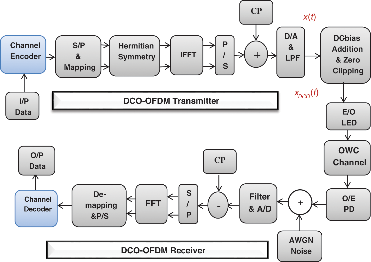
Figure 2: The proposed DCO-OFDM system with channel coding
5.2 Proposed IM/DD ACO-OFDM System Model
In ACO-OFDM, no DC bias is required to convert a bipolar signal to a unipolar signal, so that the ACO-OFDM is more efficient than the DCO-OFDM. The signal is clipped at zero levels without adding any clipping noise and without missing any information. Fig. 3 shows the block diagram of the proposed ACO-OFDM system with channel coding. In ACO-OFDM, the data symbols are carried on odd sub-carriers, but the even subcarriers are used to ensure non-negativity requirements of the transmitted OFDM signals. Only half of the sub-carriers carry the transmitted signal. Consequently, the effective data rate of ACO-OFDM is decreased by a factor of two compared to the data rate of DCO-OFDM for the same modulation format. A convolutional coding technique is proposed to enhance the ACO-OFDM performance.
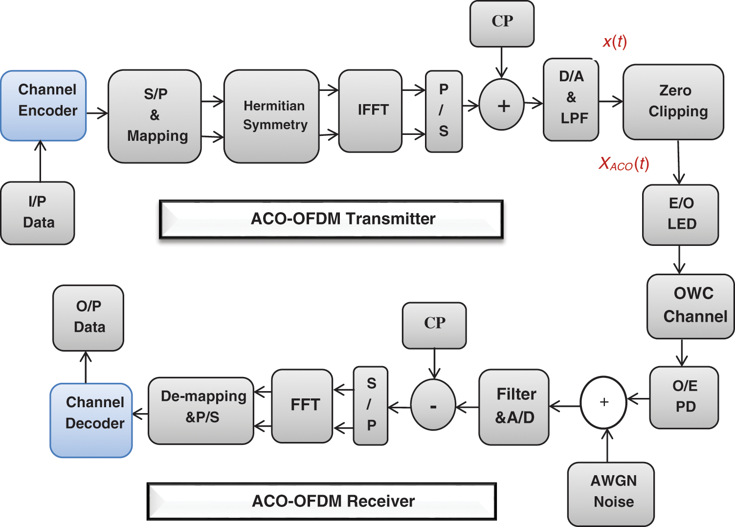
Figure 3: The proposed ACO-OFDM system with channel coding
Firstly, the input binary data is encoded by adding redundant data bits using a type of channel coding such as convolutional codes. The encoded data is serial-to-parallel conversion and mapping using (BPSK, QPSK, M-QAM). The input signal to the IFFT contains only the odd sub-carriers, as follows:
To get a real-time valued signal from the IFFT, the input vector to the IFFT, X must be forced to have a Hermitian symmetry property. Therefore, the resulting time-domain signal from IFFT is real and has an odd symmetry property, as given in the following equation.
Like the DCO-OFDM, the IFFT output signal is serially converted, and CP is appended. Then, it is D/A converted and passed through an ideal LPF, resulting in x(t). The signal, x(t), is clipped to zero to obtain the ACO-OFDM signal, xACO(t) where
5.3 Proposed IM/DD ADO-OFDM System Model
Fig. 4 shows the block diagram of the ADO-OFDM system with channel coding, which is proposed as a technique for performance enhancement. It is shown that the proposed ADO-OFDM transmitter is the same as the proposed ACO and DCO OFDM transmitter before applying the IFFT block. After that, the signal is split into two paths. The upper path generates the ACO-OFDM signal, and the lower path generates the DCO-OFDM signal.
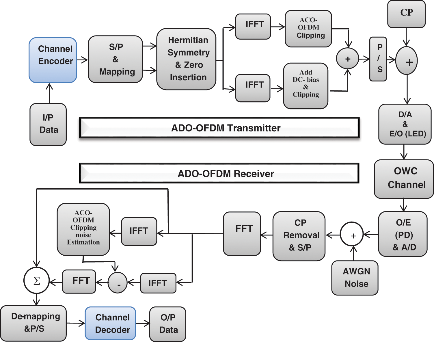
Figure 4: The proposed ADO-OFDM system with channel coding
The generated ACO-OFDM signal is defined as follows:
where
where
The proposed ADO-OFDM is the same as the ADO-OFDM except for the decoding process. At the end of the proposed ADO-OFDM receiver, the received ADO-OFDM signal is demodulated and decoded.
5.4 Proposed IM/DD Flip-OFDM System Model
Fig. 5 shows the block diagram of the proposed Flip-OFDM with channel coding. Firstly, the input binary signal is encoded by adding extra bits to it. Then, the encoded signal is mapped to complex numbers using different digital modulation techniques such as BPSK, QPSK, 4-QAM, 16-QAM, 64-QAM, or 256-QAM. After that, the system is the same as the Flip-OFDM except for the equalization process and the encoding process that is applied at the end of the receiver.
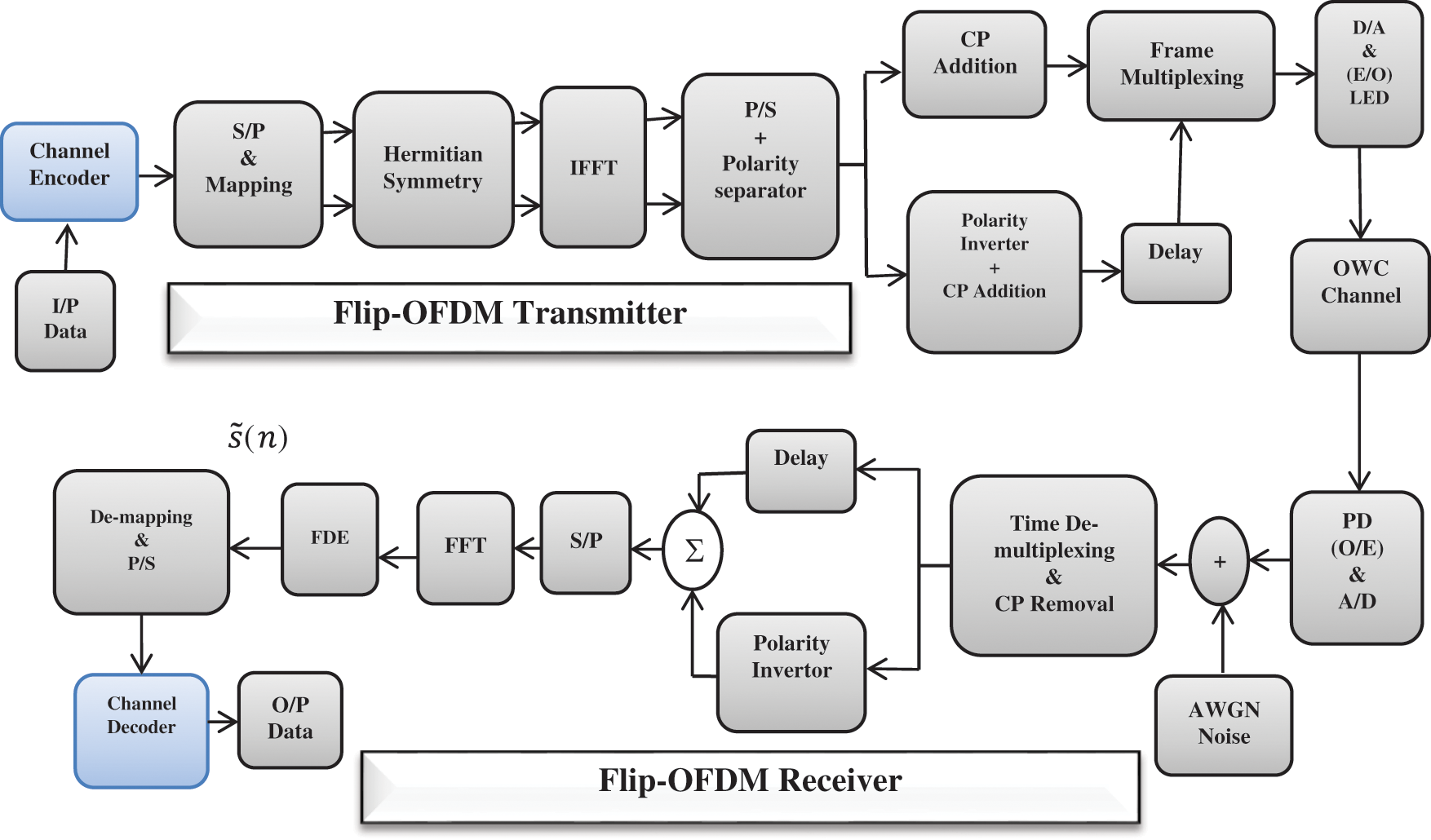
Figure 5: The proposed Flip-OFDM with channel coding
The matrix of the MMSE equalizer is given by:
where HH is the Hermitian of the channel matrix,
The performance analysis of the communication system has been estimated by finding the relation between BER and SNR. The BER has been computed by finding the ratio between the number of bit errors (NERR) and the total number of transmitted bits (NTS) as:
The number of bit errors is obtained by comparing the received bit sequence with the transmitted bit sequence.
6.1 Simulation Results for the Proposed DCO-OFDM
• AWGN Channel
The BER performance of DCO-OFDM is studied at two different values of DC biasing; 7 and 13 dB. Four cases of QAM constellation mapping are used: 4, 16, 64, and 256 QAM. The simulation parameters are 600 OFDM symbols and 1024 subcarriers in each OFDM symbol and a CP length of 24. The simulation results are shown in Figs. 6 and 7. For 7 dB biased DCO-OFDM in Fig. 6, it is noted that the BER performance decreases gradually with the increase of the constellation size. In cases of using 4 and 16 QAM, the system gives a better performance, but that performance decreases significantly in 64 and 256 QAM cases due to the clipping noise. The clipping noise can be reduced by increasing the DC bias to 13 dB, as shown in Fig. 7. BER performance for 4 and 16 QAM is still better with higher electrical power. However, the BER performance for high constellation sizes of 64 and 256 QAM is improved significantly.
Fig. 8 shows that with increasing DC bias level, the remaining negative part of the signal decreases, which leads to a decrease in the clipping noise. The signal does not need any clipping for higher biased (13 dB) DCO-OFDM because there are no remaining negative parts after adding the DC bias. It is known that channel coding can be used to improve the performance of the communication system. Therefore, convolutional coding is used as a method of channel coding to improve the performance of DCO-OFDM. This simulation experiment uses convolutional coding with code rates (1/3, 1/2, and 2/3).

Figure 6: The BER performance for 7 dB biased DCO-OFDM over AWGN channel for 4, 16, 64, and 256 QAM constellations
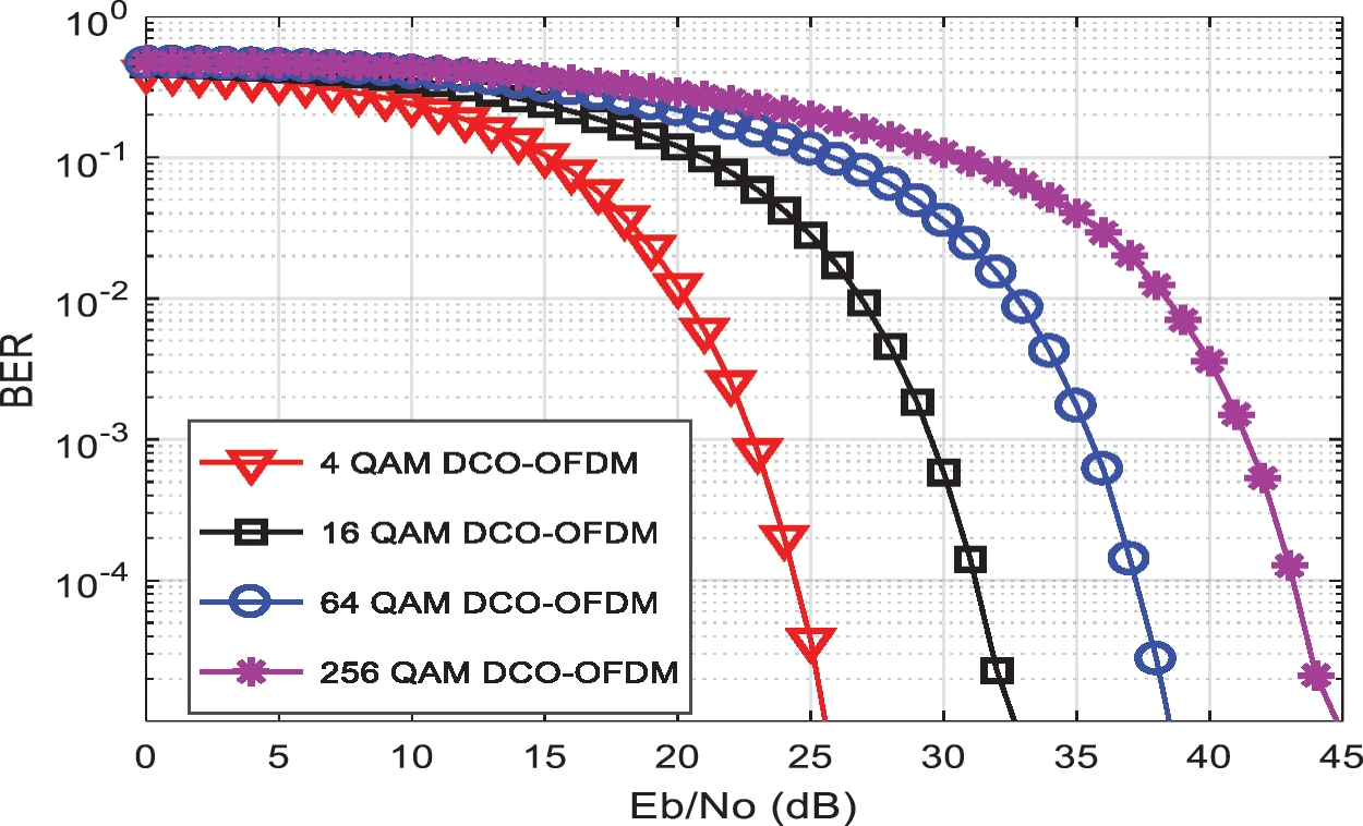
Figure 7: The BER performance for 13 dB biased DCO-OFDM over AWGN channel for 4, 16, 64, and 256 QAM constellations

Figure 8: The Time domain waveforms of DCO-OFDM signal after adding different DC biases: (a) 0 dB, (b) 5 dB, (c) 7 dB, and (d) 13 dB
In Fig. 9, un-coded DCO-OFDM is compared to convolutional coded DCO-OFDM with code rates (1/3, 1/2, and 2/3). It is noted that convolutional codes improve the BER performance of the DCO-OFDM system. For example, at a BER= 10–4, convolutional codes with code rates 1/2 and 2/3 enhance the performance by approximately 5 dB. Also, a 7 dB performance enhancement is obtained in the case of the code with a rate of 1/3 at BER = 10−4.
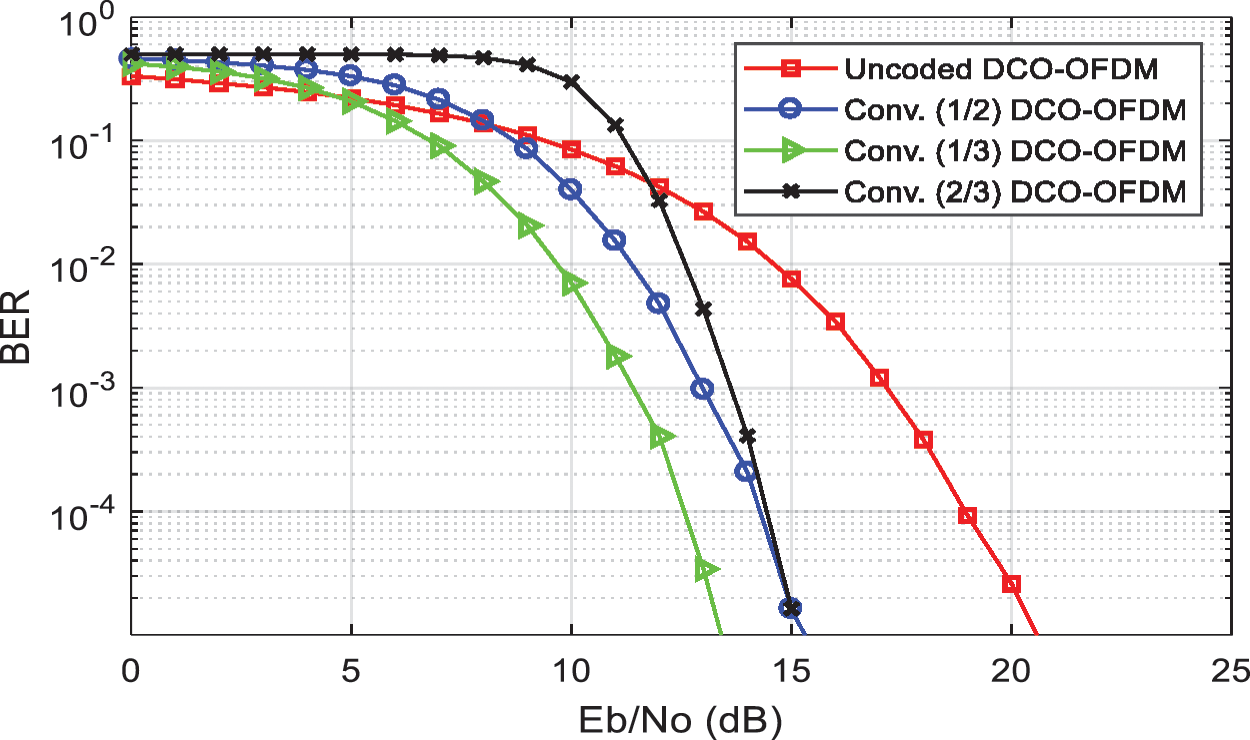
Figure 9: The performance enhancement of 7 dB biased DCO-OFDM (4QAM) over AWGN channel using convolutional code with the rate (1/3, 1/2, and 2/3)
In the case of using low-bias DCO-OFDM, the clipping noise dominates for larger constellation sizes by increasing the BER, which leads to degradation in the system performance. Convolutional codes are used to eliminate clipping noise. Therefore, the BER performance enhancement is achieved. In Fig. 10, a 7 dB bias is used in DCO-OFDM for 16 and 64 QAM constellation sizes. It is clear that the BER decreases significantly at the same Eb/N0 in the case of using convolutional codes. For example, at Eb/N0 = 25 dB, un-coded DCO-OFDM for 64 QAM gives a BER ≅ 0.13, and convolutional coded DCO-OFDM for 64 QAM gives a BER ≅ 0.0001.
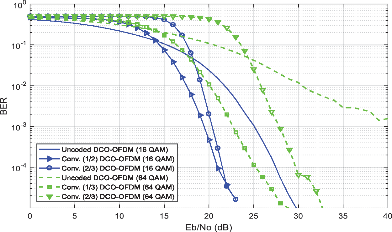
Figure 10: The performance enhancement of 7 dB biased DCO-OFDM for 16 QAM and 64 QAM constellations over AWGN channel using convolutional coding
• Log-Normal Turbulence Channel
The performance of the OWC system is sensitive to atmospheric turbulence. The DCO-OFDM IM/DD system is affected by weak atmospheric turbulence when used in free space, as shown in Figs. 11 and 12. From the results shown, it is deduced that the weak turbulence fading limits the BER performance of the DCO-OFDM system. As the turbulence strength increases, the BER performance decreases.
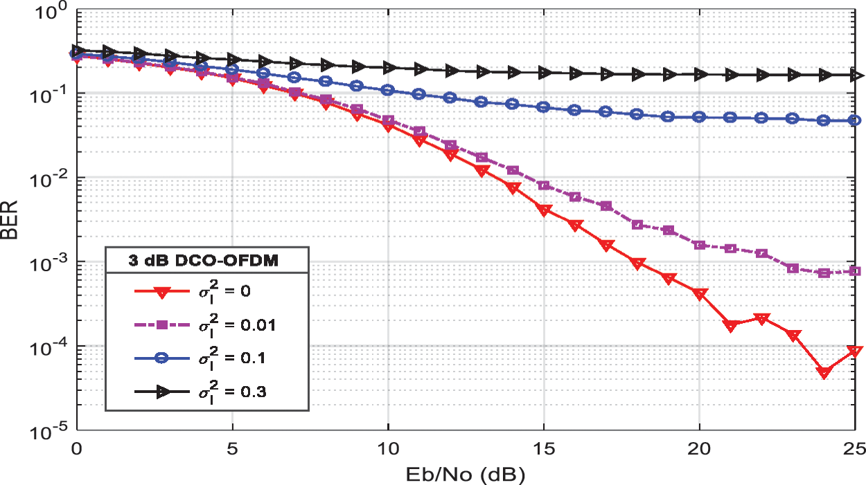
Figure 11: The effect of weak atmospheric turbulence on BER performance of DCO-OFDM system (DC bias = 3 dB, 4 QAM constellation) at different values of fading strength σl2 = (0, 0.01, 0.1 and 0.3)
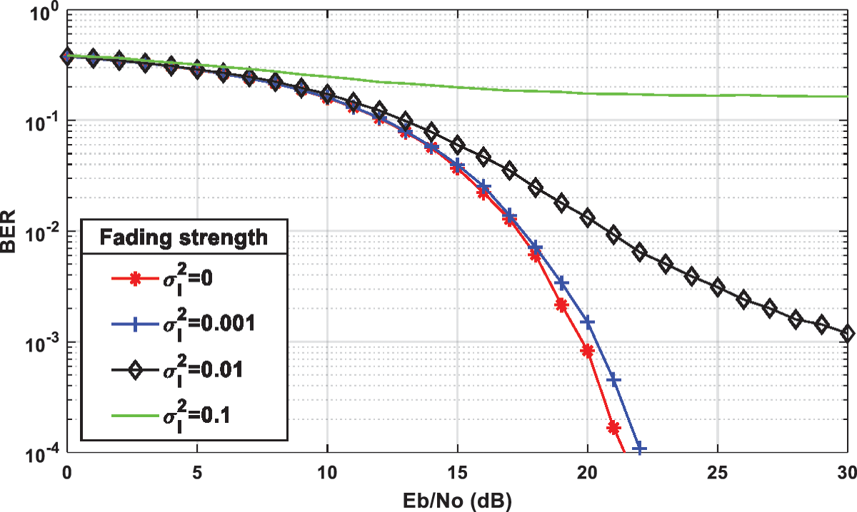
Figure 12: The effect of weak atmospheric turbulence on DCO-OFDM (DC bias = 7 dB, BPSK modulation) at fading strengths σl2 = ([0, 0.001, 0.01 and 0.1)
The effect of weak atmospheric turbulence can be mitigated by using error-correcting codes. The Hamming (7, 4) code can be used for improving the performance of the DCO-OFDM system over the log-normal turbulence channel model. The results of these simulation experiments are shown in Fig. 13. It is clear from this figure that Hamming code gives a high BER performance at σl2 = 0.01, and 0.001.

Figure 13: The Performance enhancement using hamming (7, 4) code for 7 dB DCO-OFDM (BPSK modulation) system with log-normal turbulence channel model at σl2 = (0, 0.01, 0.01 and 0.1)
6.2 Simulation Results for the Proposed ACO-OFDM
• AWGN Channel
The BER performance of the ACO-OFDM is studied over the AWGN channel for QAM constellation sizes: 4, 16, 32, 64, 256, and 1024. Convolutional codes with rates 1/2 and 1/3 are used for performance enhancement. The BER performance of the ACO-OFDM is investigated over the AWGN channel with varying QAM constellation sizes, as shown in Fig. 14. It decreases gradually with the increase in constellation size. So that, a 4 QAM gives better BER performance for ACO-OFDM systems.
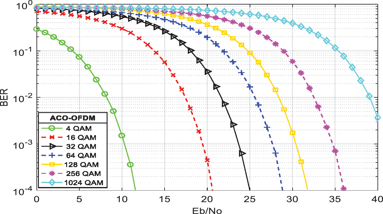
Figure 14: The BER performance of ACO-OFDM for 4, 16, 32, 64, 128, 256, and 1024 QAM constellation sizes
The improvement of BER performance of 4 QAM ACO-OFDM over AWGN channel using convolutional codes with rates 1/2 and 1/3 is demonstrated in Fig. 15. At BER = 10−3, it is seen that convolutional codes with rates 1/2 and 1/3 give better performance by approximately 4.5 and 6 dB, respectively.

Figure 15: Convolutional codes rates 1/2 and 1/3 for BER performance enhancement of ACO-OFDM with 4 QAM constellation size
6.3 Simulation Results for the Proposed ADO-OFDM
• Log-Normal Turbulence Channel Model
This section studies the BER performance of the ADO-OFDM with BPSK modulation over log-normal turbulence channels. The effect of very weak atmospheric turbulence on the ADO-OFDM system is illustrated in Fig. 16. It is seen that very weak atmospheric turbulence has a great impact on ADO-OFDM performance. For example, if the fading strength increases from 0 to 0.01, the electrical power must increase by 10 dB to get a BER = 10−4.
Figs. 17–19 present comparisons between un-coded and coded ADO-OFDM in the presence of weak atmospheric turbulence with 0.01 and 0.001 fading strength. It is noted that Hamming codes and BCH codes give performance enhancement at fading strength σl2 = 0.001. Convolutional codes enhance the performance in cases of fading strength σl2 = 0.01, and 0.001. At BER = 10−3, Fig. 17 shows that Hamming codes improve the performance by approximately 3 dB.
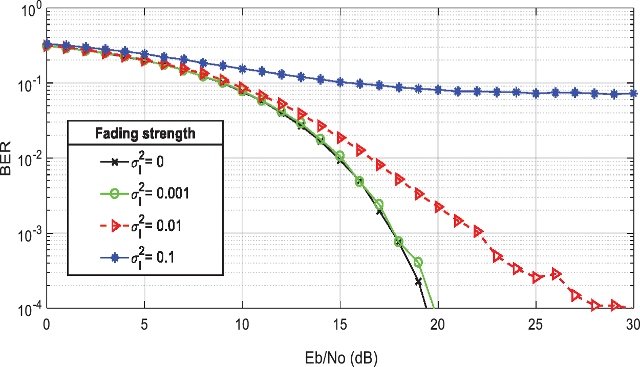
Figure 16: The effect of weak atmospheric turbulence on ADO-OFDM (BPSK modulation, DC bias = 7 dB) at fading strengths σl2 = (0, 0.001, 0.01, and 0.1)

Figure 17: The performance enhancement using hamming codes for coded ADO-OFDM over weak atmospheric turbulence with fading strength (σl2 = 0.001)
6.4 Simulation Results for the Proposed Flip-OFDM
• AWGN Channel
This section shows Matlab simulation results for Flip-OFDM. First, the BER performance of Flip-OFDM is studied over the AWGN channel with different modulation types: BPSK, QPSK, and QAM, as shown in Fig. 20. Next, ACO-OFDM and Flip-OFDM with different levels of QAM mapping are compared over the AWGN channel in Fig. 21. It is shown that both techniques have the same BER performance. Convolutional codes with code rates of 1/3, 1/2, and 2/3 and BCH (15, 5) codes are used to improve Flip-OFDM performance. Fig. 22 shows a performance comparison between un-coded Flip-OFDM and convolutional coded Flip-OFDM over the AWGN channel. It is clear that the proposed Flip-OFDM system with convolutional coding performs better than the un-coded Flip-OFDM system. For example, at BER = 10−3, the proposed Flip-OFDM with convolutional code with rate 1/2 provides improvement by approximately 3.5 dB.

Figure 18: The performance enhancement using BCH codes for ADO-OFDM over log-normal turbulence fading channel at fading strength σl2 = 0.001

Figure 19: The Performance enhancement using convolutional code with rate 2/3 for coded ADO-OFDM over log-normal turbulence channel at σl2 = 0.001, and 0.01
The BER performance of un-coded Flip-OFDM and the proposed Flip-OFDM with BCH coding for 4, and 16 QAM over AWGN channel are shown in Fig. 23. It is clear from the results that BCH coded Flip-OFDM provides a performance enhancement over the un-coded system. For example, at BER = 10−3, the proposed Flip-OFDM with BCH coding enhances 5 dB for 4 and 16 QAM.
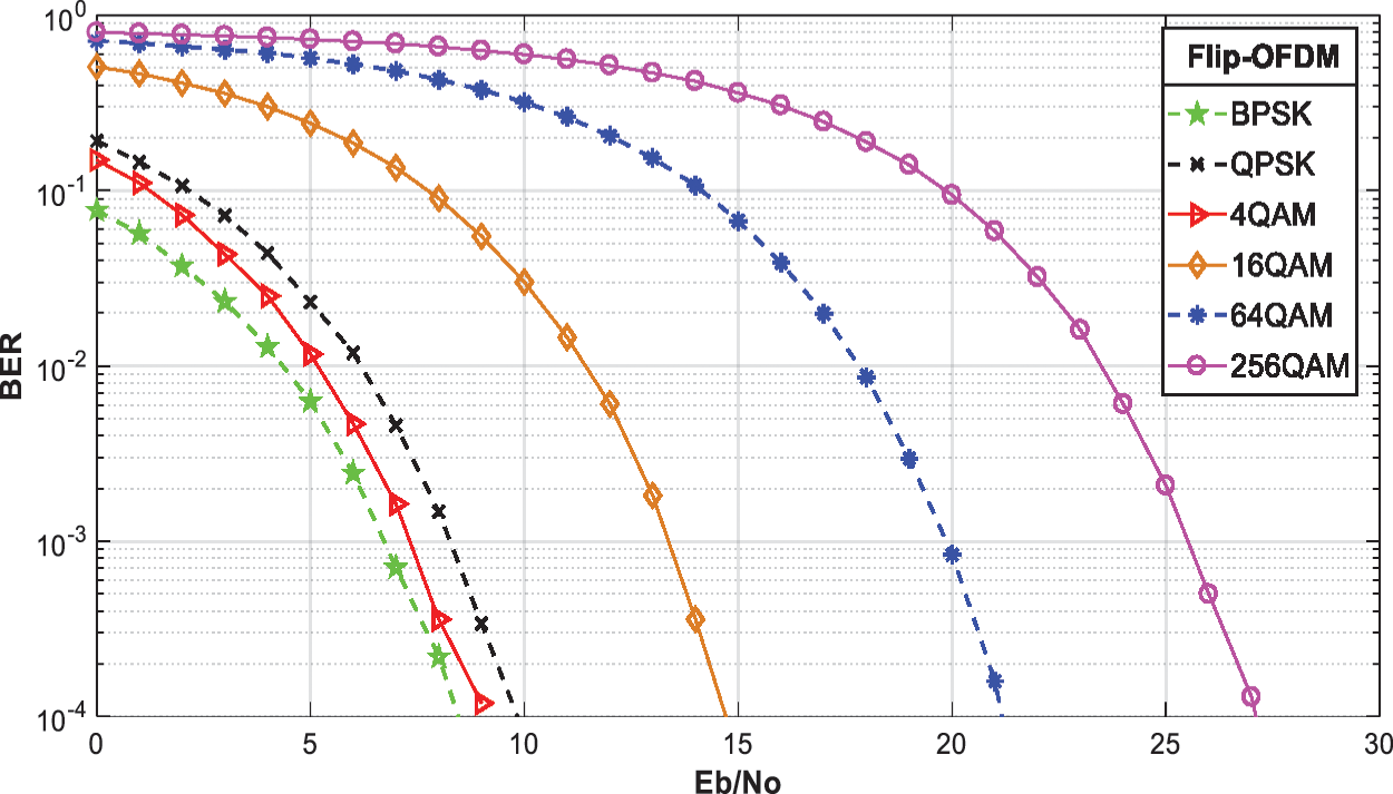
Figure 20: The BER performance of un-coded flip-OFDM over AWGN channel using different types of modulation (BPSK, QPSK, and M-QAM)

Figure 21: The BER performance comparison of ACO-OFDM and Flip-OFDM over AWGN channel for different sizes of QAM constellations
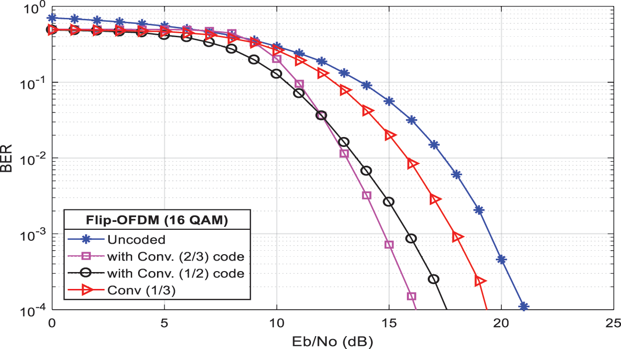
Figure 22: The BER performance enhancement using convolutional coding with rates 1/3, 1/2, and 2/3 for Flip-OFDM with 16 QAM constellation sizes over AWGN channel

Figure 23: The BCH (15, 5) code for BER performance enhancement of flip-OFDM for 4 and 16 QAM over the AWGN channel
• Ceiling Bounce Channel Model
Fig. 24 shows the BER performance of the un-coded Flip-OFDM at different levels of QAM mapping over ceiling bounce channel model using two types of frequency-domain equalizers, LS and MMSE. The results show that the MMSE equalizer outperforms the LS equalizer at all levels of QAM. For example, at BER = 10−3, the MMSE equalizer outperforms the LS equalizer by nearly 9 dB for 64 QAM Flip-OFDM.

Figure 24: The BER performance of un-coded flip-OFDM system over ceiling bounce channel model (ceiling height hc = 3.5 m) using LS, and MMSE techniques

Figure 25: The BER performance of the proposed flip-OFDM system with convolutional coding (code rate = 1/2) using LS and MMSE equalizers
Fig. 25 shows the BER performance of the proposed Flip-OFDM with convolutional coding over the ceiling bounce channel model using two types of channel estimation algorithms (LS and MMSE). From the results, it is seen that the MMSE equalizer outperforms the LS equalizer. For example, at BER = 10−3, the MMSE equalizer outperforms the LS equalizer by 8 dB for 64 QAM Flip-OFDM.
Fig. 26 demonstrates the BER performance of un-coded Flip-OFDM and the proposed Flip-OFDM with convolutional coding for codes with rates 1/3, 1/2, and 2/3 using MMSE equalizer. Results show that convolutional coding with rates 1/3, 1/2, and 2/3 provides an enhancement by nearly 8, 6.5, and 5 dB at BER = 10−3, respectively.

Figure 26: The BER performance comparison of un-coded flip-OFDM and proposed Flip-OFDM with convolutional coding over ceiling bounce channel model using MMSE equalizer
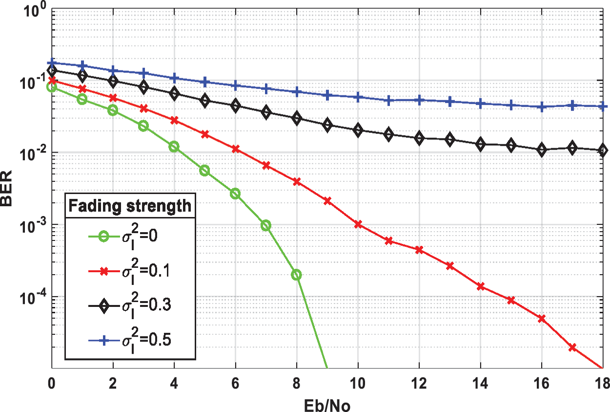
Figure 27: The effect of weak atmospheric turbulence with fading strengths σl2 = [0, 0.1, 0.3, and 0.5] on BER performance of Flip-OFDM

Figure 28: Hamming (7, 4) code for performance enhancement of flip-OFDM with the effect of weak atmospheric turbulence with fading strengths σl2 = [0, 0.1, 0.3, and 0.5]

Figure 29: The BER performance enhancement for flip-OFDM with (BPSK, QPSK, 4QAM) modulation type with weak atmospheric turbulence at σl2 = 0.1, using convolutional code (code rate = 1/2, constraint length = 3)
• Log-Normal Turbulence Channel Model
Fig. 27 presents the effect of weak atmospheric turbulence with different fading strengths σl2 on BER performance of Flip-OFDM. Fig. 28 introduces the performance enhancement of Flip-OFDM with Hamming (7, 4) code and the effect of weak atmospheric turbulence with different fading strengths. Fig. 29 shows the BER performance enhancement for Flip-OFDM with (BPSK, QPSK, 4QAM) modulation type with weak atmospheric turbulence at σl2 = 0.1, using convolutional code with a code rate = 1/2, and a constraint length = 3. Fig. 30 compares un-coded and proposed Flip-OFDM with BCH coding in the weak atmospheric turbulence fading channel at fading strengths (0, 0.1, 0.3, and 0.5).
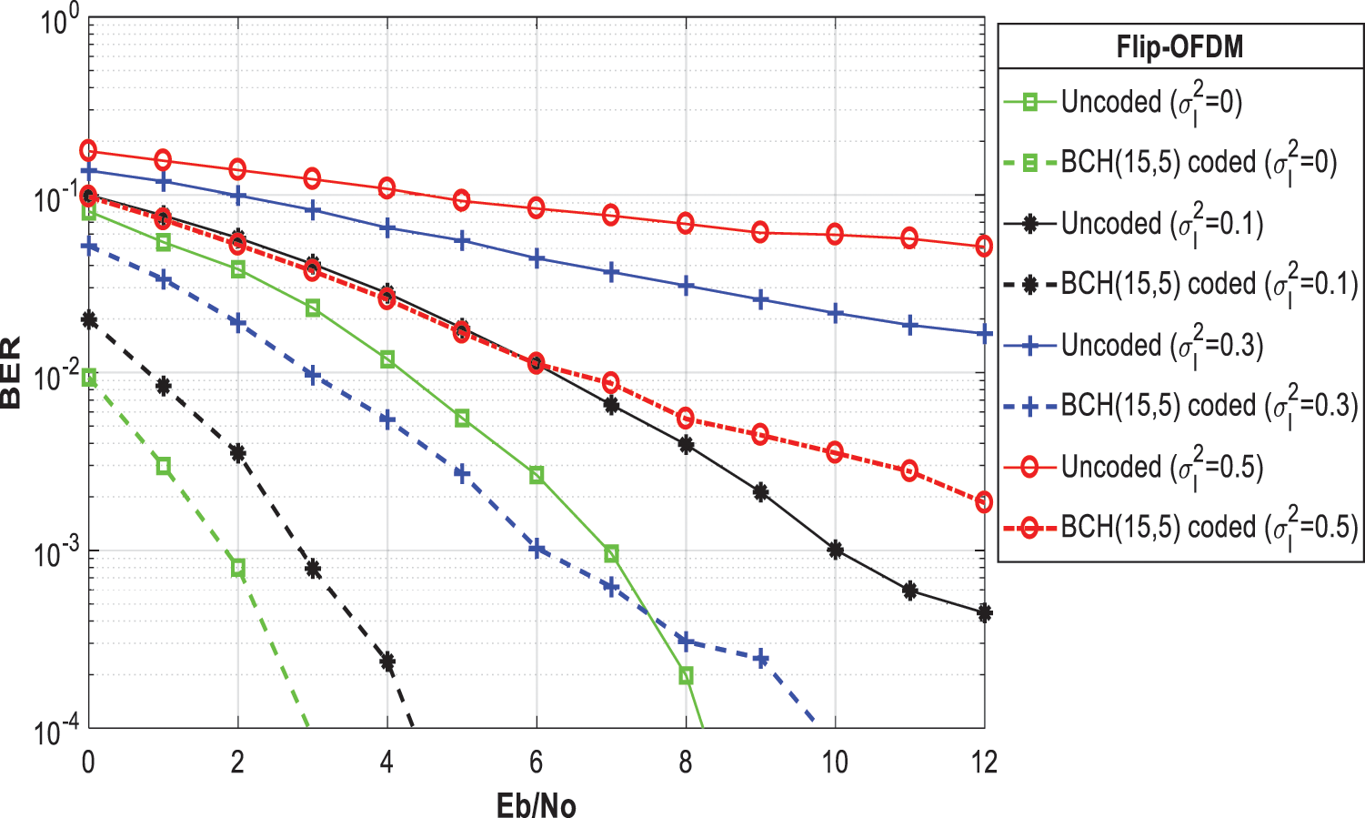
Figure 30: The BCH (15, 5) code for performance enhancement of flip-OFDM in the presence of weak atmospheric turbulence at fading strengths σl2 = [0, 0.1, 0.3, and 0.5]
This paper studied the performance of OWC IM/DD systems based on four forms of unipolar OFDM with different communication channel models. The objective of the work presented in the thesis is to enhance the performance of these systems using different techniques. This study was divided into three parts. Firstly, the BER performance of the DCO-OFDM, ACO-OFDM, ADO-OFDM, and Flip-OFDM IM/DD system was studied over the AWGN channel. Hamming, BCH, and convolutional codes have been used for performance enhancement. The coded systems were compared with the un-coded systems, and the performance enhancement with coding was elaborated. Secondly, the BER performance of the IM/DD OFDM system was studied over the ceiling bounce channel model. Two channel estimation and equalization algorithms have been considered and compared: the LS algorithm and the MMSE algorithm. The simulation results show that the MMSE algorithm gives better BER performance than the LS algorithm. Then, convolutional code was utilized for BER performance enhancement. Finally, the effect of weak atmospheric turbulence was studied on IM/DD OFDM system by studying the BER performance of the system over the log-normal turbulence channel model. The obtained results show that the weak atmospheric turbulence gradually decreases the BER performance of the IM/DD OFDM system with an increase in fading strength. Also, Hamming, BCH, and convolutional codes were utilized to mitigate the effect of very weak atmospheric turbulence. For future work, the suggested signal processing tools could be employed in advanced 5G communication networks with different types of modulation techniques.
Acknowledgement: The authors would like to thank the support of the Deanship of Scientific Research at Princess Nourah bint Abdulrahman University.
Funding Statement: This research was funded by the Deanship of Scientific Research at Princess Nourah Bint Abdulrahman University through the Fast-track Research Funding Program.
Conflicts of Interest: The authors declare that they have no conflicts of interest to report regarding the present study.
1. D. Kwon and S. Kim, “Experimental demonstration of micro LED-to-LED visible light communications,” The Journal of the Korea Institute of Electronic Communication Sciences, vol. 16, no. 2, pp. 219–226, 2021. [Google Scholar]
2. B. Majlesein, A. Gholami and Z. Ghassemlooy, “Investigation of the scattering noise in underwater optical wireless communications,” Sci, vol. 3, no. 2, pp. 1–27, 2021. [Google Scholar]
3. M. Gupta, G. Agrawal, N. Kumari and R. Rani, “Bit error rate analysis for indoor optical wireless communication system,” in Proc. Advances in Smart Communication and Imaging Systems, Springer, Singapore, pp. 423–431, 2021. [Google Scholar]
4. J. Zhong, J. Zhou, S. Gao and W. Liu, “Secure orthogonal time-frequency multiplexing with two-dimensional encryption for optical-wireless communications,” Chinese Optics Letters, vol. 19, no. 5, pp. 1–16, 2021. [Google Scholar]
5. A. Khalid, F. Rashid, U. Tahir, H. Asif and F. Al-Turjman, “Multi-carrier visible light communication system using enhanced sub-carrier index modulation and discrete wavelet transform,” Wireless Personal Communications, vol. 15, no. 2, pp. 1–29, 2021. [Google Scholar]
6. Y. Almadani, D. Plets, S. Bastiaens, W. Joseph, M. Ijaz et al., “Visible light communications for industrial applications—Challenges and potentials,” Electronics, vol. 9, no. 12, pp. 21–57, 2020. [Google Scholar]
7. S. Hashemi, Z. Ghassemlooy, L. Chao and D. Benhaddou, “Orthogonal frequency division multiplexing for characterization of dynamic distortion in LED light output for optical wireless communications,” Photonics Research, vol. 9, no. 6, pp. 916–928, 2021. [Google Scholar]
8. H. Yang, W. Zhong, C. Chen and A. Alphones, “Integration of visible light communication and positioning within 5G networks for internet of things,” IEEE Network, vol. 34, no. 5, pp. 134–140, 2020. [Google Scholar]
9. Z. Li, “Research and implementation on OFDM technology for machine communication,” Journal of Physics: Conference Series, vol. 1486, no. 4, pp. 42–50, 2020. [Google Scholar]
10. M. Mahmud, M. Hossain, A. Khan, S. Ahmed, M. Mahmud et al., “Performance analysis of OFDM, W-OFDM and F-OFDM under rayleigh fading channel for 5G wireless communication,” in Proc. of 3rd Int. IEEE Conf. on Intelligent Sustainable Systems (ICISSThoothukudi, India, pp. 1172–1177, 2020. [Google Scholar]
11. X. Wang, X. Liu, H. Chen and W. Meng, “Complementary coded CDMA systems with CP-free OFDM,” IEEE Transactions on Vehicular Technology, vol. 69, no. 10, pp. 11515–11528, 2020. [Google Scholar]
12. X. Sun, C. Kang, M. Kong, O. Alkhazragi, Y. Guo et al., “A review on practical considerations and solutions in underwater wireless optical communication,” Journal of Lightwave Technology, vol. 38, no. 2, pp. 421–431, 2020. [Google Scholar]
13. S. Hu, J. Zhang, J. Tang, W. Jin, R. Giddings et al., “Data-aided iterative algorithms for linearizing IM/DD optical transmission systems,” Journal of Lightwave Technology, vol. 39, no. 9, pp. 2864–2872, 2021. [Google Scholar]
14. A. Benieddi, S. Elahmar, I. Dayoub and S. Haxha, “Blind adaptive low-complexity time-domain equalizer for 100-gb/s direct-detection optical OFDM systems over long-reach SSMF,” IEEE Systems Journal, vol. 3, pp. 1–7, 2021. [Google Scholar]
15. J. Linnartz and X. Deng, “Continuous phase flip-OFDM in optical wireless communications,” Signal Processing, vol. 2, no. 10, pp. 63–79, 2021. [Google Scholar]
16. J. Pradhan, V. Kappala and S. Das, “Performance analysis of a Li-Fi system under ambient light conditions,” in Proc. of IEEE National Conf. on Communications (NCCKharagpur, India, pp. 1–6, 2020. [Google Scholar]
17. Z. Zhou, J. He, J. Ma and M. Chen, “Experimental demonstration of an SFO-robustness scheme with fast OFDM for IMDD passive optical network systems,” Journal of Lightwave Technology, vol. 38, no. 20, pp. 5608–5616, 2020. [Google Scholar]
18. A. Muhammed, M. Abd-Elnaby, A. Sami and F. Abd El-Samie, “Efficient coding techniques for ADO-OFDM in IM/DD systems,” Photonic Network Communications, vol. 36, no. 5, pp. 128–139, 2018. [Google Scholar]
19. A. Muhammed, M. Abd-Elnaby, A. Sami and F. Abd El-Samie, “Efficient coding techniques for flip-OFDM in IM/DD systems,” International Journal of Electronics Letters, vol. 5, no. 3, pp. 204–223, 2017. [Google Scholar]
20. S. Verma and S. Vashist, “Performance of DCO-OFDM in optical wireless communication system,” International Journal of Innovative Research in Advanced Engineering (IJIRAE), vol. 3, no. 5, pp. 1–13, 2016. [Google Scholar]
21. R. Islam, P. Choudhury and M. Islam, “Analysis of DCO-OFDM and flip-OFDM for IM/DD optical-wireless system,” in Proc. IEEE Int. Conf. on Electrical and Computer Engineering (ICECEDhaka, Bangladesh, pp. 32–35, 2014. [Google Scholar]
22. S. Trenkwalder, I. Esnaola, Y. Lopes, A. Kolling and R. Groß, “Swarmcom: An infra-red-based mobile ad-hoc network for severely constrained robots,” Autonomous Robots, vol. 44, no. 1, pp. 93–114, 2020. [Google Scholar]
23. E. Zedini, A. Kammoun, H. Soury, M. Hamdi and M. Alouini, “Performance analysis of dual-hop underwater wireless optical communication systems over mixture exponential-generalized gamma turbulence channels,” IEEE Transactions on Communications, vol. 68, no. 9, pp. 5718–5731, 2020. [Google Scholar]
24. V. Semerenko and O. Voinalovich, “The simplification of computationals in error correction coding,” Technology Audit and Production Reserves, vol. 3, no. 2, pp. 24–28, 2021. [Google Scholar]
25. W. El Shafai, B. Hrušovský, M. El-Khamy and M. El-Sharkawy, “Joint space-time-view error concealment algorithms for 3D multi-view video,” in Proc. of 18th IEEE Int. Conf. on Image Processing, (ICIPBrussels, Belgium, pp. 2201–2204, 2011. [Google Scholar]
26. W. El-Shafai, S. El-Rabaie, M. El-Halawany and F. Abd El-Samie, “Encoder-independent decoder-dependent depth-assisted error concealment algorithm for wireless 3D video communication,” Multimedia Tools and Applications, vol. 77, no. 11, pp. 13145–13172, 2018. [Google Scholar]
27. W. El-Shafai, “Joint adaptive pre-processing resilience and post-processing concealment schemes for 3D video transmission,” 3D Research, vol. 6, no. 1, pp. 1–10, 2015. [Google Scholar]
 | This work is licensed under a Creative Commons Attribution 4.0 International License, which permits unrestricted use, distribution, and reproduction in any medium, provided the original work is properly cited. |