DOI:10.32604/cmc.2022.022470
| Computers, Materials & Continua DOI:10.32604/cmc.2022.022470 | |
| Article |
Radio Optical Network Simulation Tool (RONST)
1Department of Electronics and Communications, Faculty of Engineering, Mansoura University, Dakahlia, 35516, Egypt
2Nanotechnology and Nanoelectronics Program, Zewail City of Science and Technology, Giza, 12578, Egypt
3Department of Electronics and Communications, Faculty of Engineering, Cairo University, Giza, 12613, Egypt
4Department of Electronics and Communications, Faculty of Engineering, Ain Shams University, Cairo, 11566, Egypt
5Laboratory of Micro Optics, Faculty of Information Engineering and Technology, German University in Cairo, 11835, Cairo, Egypt
6National Institute of Laser Enhanced Sciences, Cairo University, Giza, 12613, Egypt
7Wireless Intelligent Networks Center (WINC), Nile University, Giza, 12677, Egypt
*Corresponding Author: Tawfik Ismail. Email: tismail@cu.edu.eg
Received: 09 August 2021; Accepted: 19 October 2021
Abstract: This paper presents a radio optical network simulation tool (RONST) for modeling optical-wireless systems. For a typical optical and electrical chain environment, performance should be optimized concurrently before system implementation. As a result, simulating such systems turns out to be a multidisciplinary problem. The governing equations are incompatible with co-simulation in the traditional environments of existing software (SW) packages. The ultra-wideband (UWB) technology is an ideal candidate for providing high-speed short-range access for wireless services. The limited wireless reach of this technology is a significant limitation. A feasible solution to the problem of extending UWB signals is to transmit these signals to end-users via optical fibers. This concept implies the need for the establishment of a dependable environment for studying such systems. Therefore, the essential novelty of the proposed SW is that it provides designers, engineers, and researchers with a dependable simulation framework that can accurately and efficiently predict and/or optimize the behavior of such systems in a single optical-electronic simulation package. Furthermore, it is supported by a strong mathematical foundation with integrated algorithms to achieve broad flexibility and low computational cost. To validate the proposed tool, RONST was deployed on an ultra-wideband over fiber (UWBoF) system. The bit error rate (BER) has been calculated over a UWBoF system, and there is good agreement between the experimental and simulated results.
Keywords: Optical-wireless systems; mathematical modelling techniques; opto-electronic software tools; ultra-wide band over fiber systems (UWBoF)
Among the computer-aided design (CAD) tools, software developers, and end-users, it is postulated that no simulation tool can bring a wide range of physically diverse systems onto a single fully comprehensive simulation platform. The optical-wireless system is a real example of such a principle consisting of different carriers’ phenomena. Simulink, developed by MathWorks, and COMSOL approach this principle; however, both simulation platforms failed to provide a completely satisfactory solution. The same is true for optical CAD tools, which face a similar issue due to the diversity of optical sciences themselves. They are extremely diverse according to the most straightforward classification of engineering optics that lies under one of the four categories: geometrical optics, wave optics, electromagnetic optics, and quantum optics [1]. For example, CAD tools developed by LINOS Products are devoted to simulating geometrical optical systems, in which the primary concern of photo design is the development of bulk-optics systems.
On the other hand, various SW packages have been developed to simulate radio frequency (RF) and optical systems individually. However, only a few of these design tools are simultaneously concerned with the simulation of both RF and optical systems. It is readily apparent that the developers of RF CAD design tools such as the High-Frequency Structure Simulator (HFSS) and the Applied Computational Sciences tool (ACS) are unconcerned with integrating optical components, devices, and/or systems into their RF libraries. Later, we will explore some critical differentiation in the underlying principles of several of these hybrid design CAD tools. Such a research problem is addressed in the proposed radio optical network simulation tool by introducing a fully SW package for modeling optical-wireless systems over a single and effective platform without any integration process with the other tools. The physical and mathematical background has been processed using a multi-step procedure.
At first, we have started with a semi-analytical approach to identify the key design parameters and establish the mathematical framework from which the theoretical guidelines are naturally derived. A comprehensive simulation study based on existing SW packages was carried out to verify the mathematical modeling techniques. As a result, for the first time, we were able to develop a reliable CAD tool with an adaptive mathematical solver based on different numerical modeling techniques that could be used to serve a wide range of different systems in a more applicable and efficient manner. Finally, a series of verification experiments, depending on the available equipment, have been performed to validate and check the precision of the proposed simulation tool. These experiments have been implemented to be close to realistic scenarios usually encountered in access and in-building networks. Additionally, the developed SW package will be used in conjunction with the proposed module, UWBoF, to evaluate its standalone efficiency from the perspective of an end-user. The RONST layout is developed after accumulating all of the information necessary about the components and including it in the constituting libraries. The modeling and simulation of the components’ libraries are conducted via MATLAB, Python, and C++ programming languages.
The rest of this paper is organized as follows. A brief description of an UWBoF module is presented in Section II. The characteristics of the presented CAD tool are explained in Section III. The simulation and experimental results are highlighted in Section IV to validate the workability of the presented CAD tool. Finally, a conclusion has been drawn.
2 Ultra-Wide Band Over Fiber System
UWB is a fast-growing successful technology and a suitable candidate for many communications applications due to the numerous advantages offered by this technology, which perfectly suits the needs of high data rate-short-range wireless communication networks [2,3]. UWB signals show high robustness in dense multipath fading environments [4,5]. Moreover, low power consumption and very low levels of spectral emission are some of the advantages of this technology [6]. However, these properties may cause mutual interference problems due to coexistence with other conventional narrowband radio systems. Therefore, the US Federal Communications Commission (FCC) has licensed the use of the spectrum for UWB communications, with a maximum effective isotropic radiated power (EIRP) spectral density (PSD) of −41.3 dBm/MHz to avoid coexistence problems with currently existing narrowband systems [7].
This upper spectral bound can be reached throughout a wide band of 7.5 GHz of the spectrum ranging from 3.1 to 10.6 GHz. According to the FCC report, a UWB signal should occupy at least 500 MHz of the spectrum or equivalently has a minimal fractional bandwidth of 20% [7]. In the design of UWB systems, efficient integration is targeted with the other wireless technologies [8,9]. Moreover, considerable utilization of the acceptable power level and the available bandwidth is one of the key challenges to generate UWB pulses with high spectral and power efficiencies while respecting the FCC spectral constraints.
The band-limited signals that exactly follow the FCC mask within the mentioned useful UWB band possess an EIRP that does not exceed 0.56 mW or equivalently −2.5 dBm. Such extremely low radiation transmission power is further decreased due to the path loss inherent in wireless channels even if multipath propagation is prohibited and free space propagation is hypothesized. This extremely low received power effectively limits the reach of a UWB signal to about 4∼10 m preventing geographically remote users from accessing such systems. A feasible solution to this problem is to transmit UWB signals to those users via optical fibers leading to the concept of the UWBoF system [10–14]. Fig. 1 depicts a general block diagram describing the photonic generation, transmission, and detection processes by the optical generation techniques utilized in UWBoF systems. A set of communication processing techniques such as pulse shaping and modulation are applied on a basis function, usually having a Gaussian profile, that drives the system in the optical domain by employing microwave photonic (MWP) techniques [15–19]. Then, the signal can be transmitted over a standard single-mode fiber (SMF) to a remote area and finally detected in the electrical domain through a photodetector (PD).
The detected waveform is then transmitted to the target location, which may be several kilometers away from the original access point, via a UWB transmitting antenna (Tx), where it is picked up by the remote user's UWB receiving antenna (Rx). In the presented module, the UWB signal is derived from an impulse radio (IR) signal, a sequence of modulated impulses like waveforms with a short duration, typically less than 2 ns, that is transmitted over a radio channel. Another important consideration that has a significant impact on the overall performance of a UWBoF system is the careful design of the IR-UWB waveforms used to encode UWB information signals [20–22].
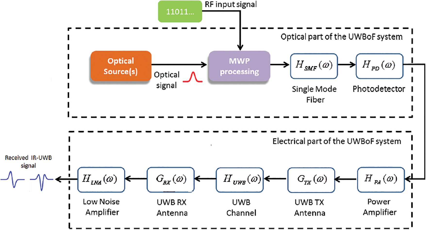
Figure 1: Typical block diagram of an UWBoF system with optical and electrical chains
2.2 System Background Analysis
In order to identify the design parameters, a mathematical analysis for an UWBoF system has been performed by our research group which is documented in a series of publications [22–26]. It is started with the development of closed-form expressions for the IR-UWB waveforms to maximize the received electrical signal-to-noise ratio (SNR) and ended with the appropriate analysis and design of radiative-efficient UWB antennas. Such analysis has been considered in the source codes of RONST. The source code of each component, in Fig. 1, has been encapsulated in its own transfer function. The multiplication of the cascaded transfer functions of the system components leads to the overall input-output relationship.
3 Radio Optical Network Simulation Tool
The suggested CAD tool is a block diagram SW package with a multi-layered architecture for research or industrial development, such as testing, design, analysis, and simulation. It also works as an optimization platform for long-haul links or the last-mile connection before installing at the end-user. It consists of three layers, as shown in Fig. 2. The first layer is where all the programming tasks take place. Due to the powerful capabilities offered by MATLAB and Python as a programming environment and computing tools, the core programming of RONST relies on a MATLAB-based Python source code, which is responsible for the modeling and the characterization phase. However, in our case, a collaborative simulation using C++ is employed to assess the interfacing for the hardwired modules with the source codes. This high-level programming language is masked by a further attractive and easy-to-use graphical user interface (GUI), as shown in Fig. 3.
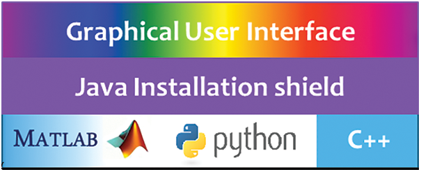
Figure 2: Multi-layer software architectural design of the proposed CAD tool. Lower layer: high level programming languages. Higher layer: presentation layer viewed to the user via a graphical user interface
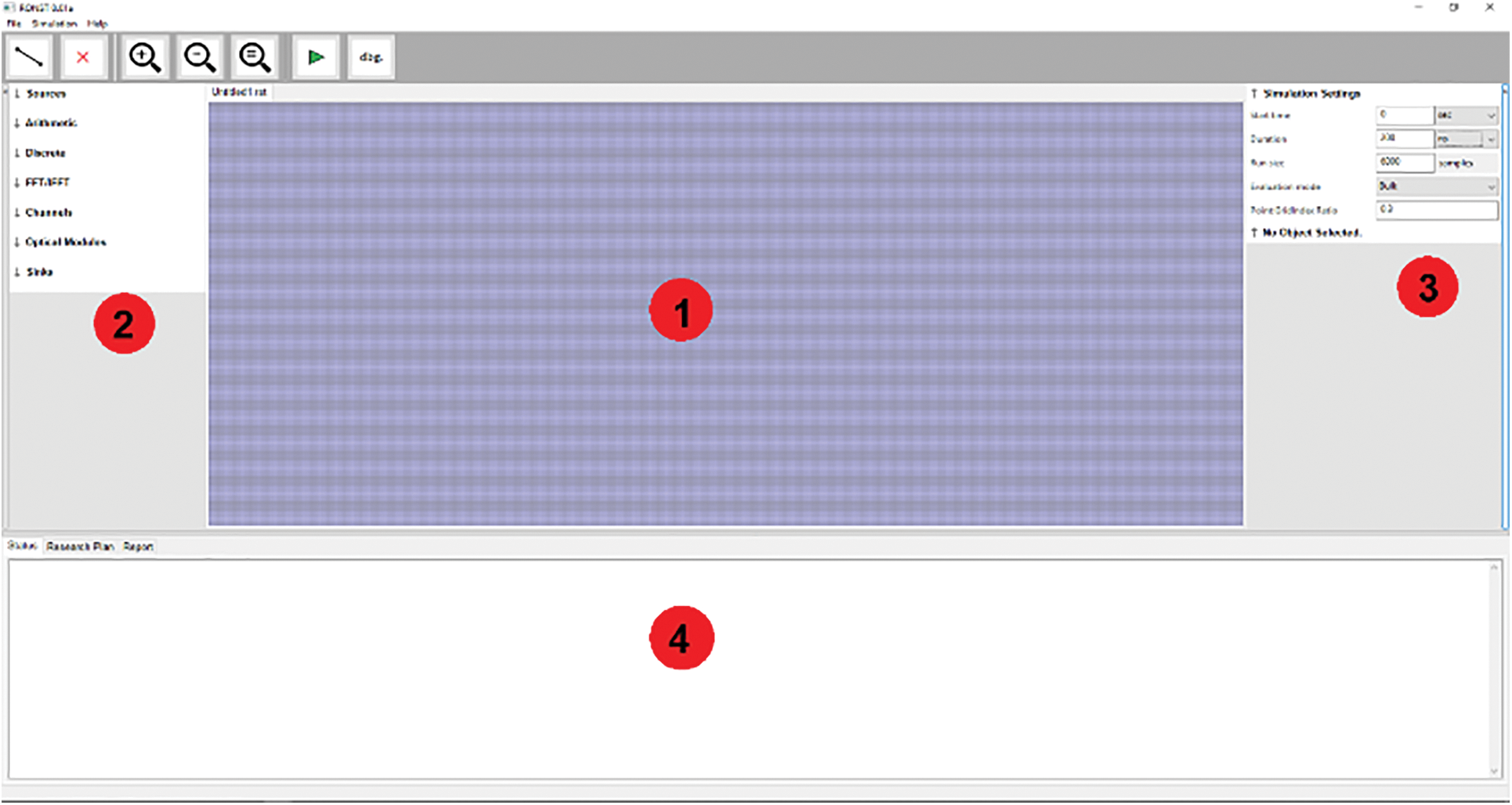
Figure 3: RONST GUI; 1) Workspace: includes the system design, 2) Components: optical, electrical and wireless, 3) Configuration settings: for each used component in the system, and 4) Messages and logs: include errors, warnings, reports and the run status
In order to develop a standalone SW package, which usually works under a Windows environment, the operating system interface and the installation shield shall be developed by establishing the necessary dynamic link library (.dll) files and Java scripts. The main role of this layer is to present easy-to-access facilities for the user while masking most of the potential of the programming environment. The GUI workbench layer is where all the tools and component libraries exist, and the user can establish the project workspace. Typically, this layer consists of the toolbars, menus, and component libraries. Further, taskbars can be created according to the individual design of this space. The component libraries are proposed to develop a wealth of components classified under the following categories: 1) Optical components, 2) RF components, 3) Microwave Photonics components, 4) Wireless Transmission, 5) Communications Functions, 6) Digital Signal Processing components, 7) General Purpose components, 8) General Purpose Mathematics, 9) Data Analysis and Visualization, and 10) Optimization Tools.
3.2 Numerical Modeling Approach
In general, the analytical solution of the full-vectorial wave equation for a nonlinear optical system with multiple discontinuities does not exist. The wave equation is a second-order partial differential equation (PDE) with four dimensions, three spatial and one temporal. It is represented as follows:
where
The finite-difference time-domain (FDTD) is a numerical technique that has proved its efficiency in solving PDEs and characterizing many problems [28–31]. However, in the case of increasing the dimensions or the complexity of the problem domain, the solution will need more computational resources in terms of time and memory. Further, the FDTD is not accurate enough, especially with the existence of the stair-casing problem [32,33]. The finite element method (FEM) is a very accurate numerical technique. It consists of various mesh elements interpolated with different order of shape functions to cover the solution domain in the most efficient and less computational method [34,35]. It is widely used even in other scientific fields due to its reliability and flexibility as a modeling method [36,37]. The FEM is involved in RONST for the modal solution of the wave equation and to get the spatial distribution of the optical fields.
For the standard telecommunication silica fibers where the nonlinear effects are relatively weak, the wave equation has been derived in the frequency domain after ignoring the nonlinear polarization as follows,
where
where
where
in which the matrices for each mesh element are assembled in K, the characteristic matrix, and M, the global mass matrix. The FEM solution has been developed based on the weighted-residual technique assumption [34], therefore, the matrices
where
For the propagation analysis, a non-iterative bidirectional beam propagation method (NI-BiBPM) is adopted. The NI-BiBPM is a numerical technique that proves an excellent efficiency in solving systems with multiple discontinuities. The non-iterative algorithm has achieved accurate results in only one sweep analysis reducing the dimensionality of the problem and the time of calculations [38–40]. The NI-BiBPM represents such problems by transition and propagation operators. The transition operators link between the transmitted and reflected field components around each discontinuity
where
In order to avoid the lengthy and complicated process of the modal analysis while running RONST source codes, some techniques have been considered. At first, the lumping rule was adopted to convert the global mass matrix, M, into a diagonal matrix [41]. Then, the inverse of the resulted matrix is multiplied into K. The lumped mass matrix and the modified characteristic matrix are represented in (11) and (12), respectively.
Secondly, the square root operator in the transition and propagation formulas has been calculated using blocked Schur (BS) algorithm [42]. BS has proved a reliable stability vs. the iterative techniques such as Taylor series expansion and Padé approximation [38]. The characteristic matrix is decomposed into an upper triangular matrix representing all the eigenmodes in its diagonal entries as shown in (13),
where Q is a unitary matrix and U is an upper triangular matrix. As a result, the
The elements of
The formulas in (15) and (16) can be solved either a column or a super-diagonal at a time. A standard blocking scheme is applied over
The proposed analysis guarantees more stability especially in cases with very high index contrast discontinuities such as in plasmonics structures [43].
Most of assumptions and approximations usually depend on the situation at hands. For example, in the nonlinear photonic crystal fibers, the linear propagation assumption resulting from the weak variations in the envelope approximation may be violated. Therefore, in order to build a generalized and powerful SW package, such phenomena have been considered in RONST. The inclusion of nonlinear effects provides a study of phenomena such as the four-wave mixing and self-phase modulation which exist in practice and are ignored by most current SW packages. Starting with the wave equation in (1), the nonlinear polarization
3.3 Capabilities and Limitations
The purpose of this section is devoted to exploring and comparing the newly developed features of RONST with the capabilities and limitations of the three top similar and familiar SW packages that have gained a wide trust among the research community. These SW packages are VPI Transmission Maker, developed by VPI Photonics, INTERCONNECT, developed by Lumerical, and Opti-System, developed by Optiwave. In Tab. 1, the properties of these tools are summarized and compared with the proposed RONST SW package.
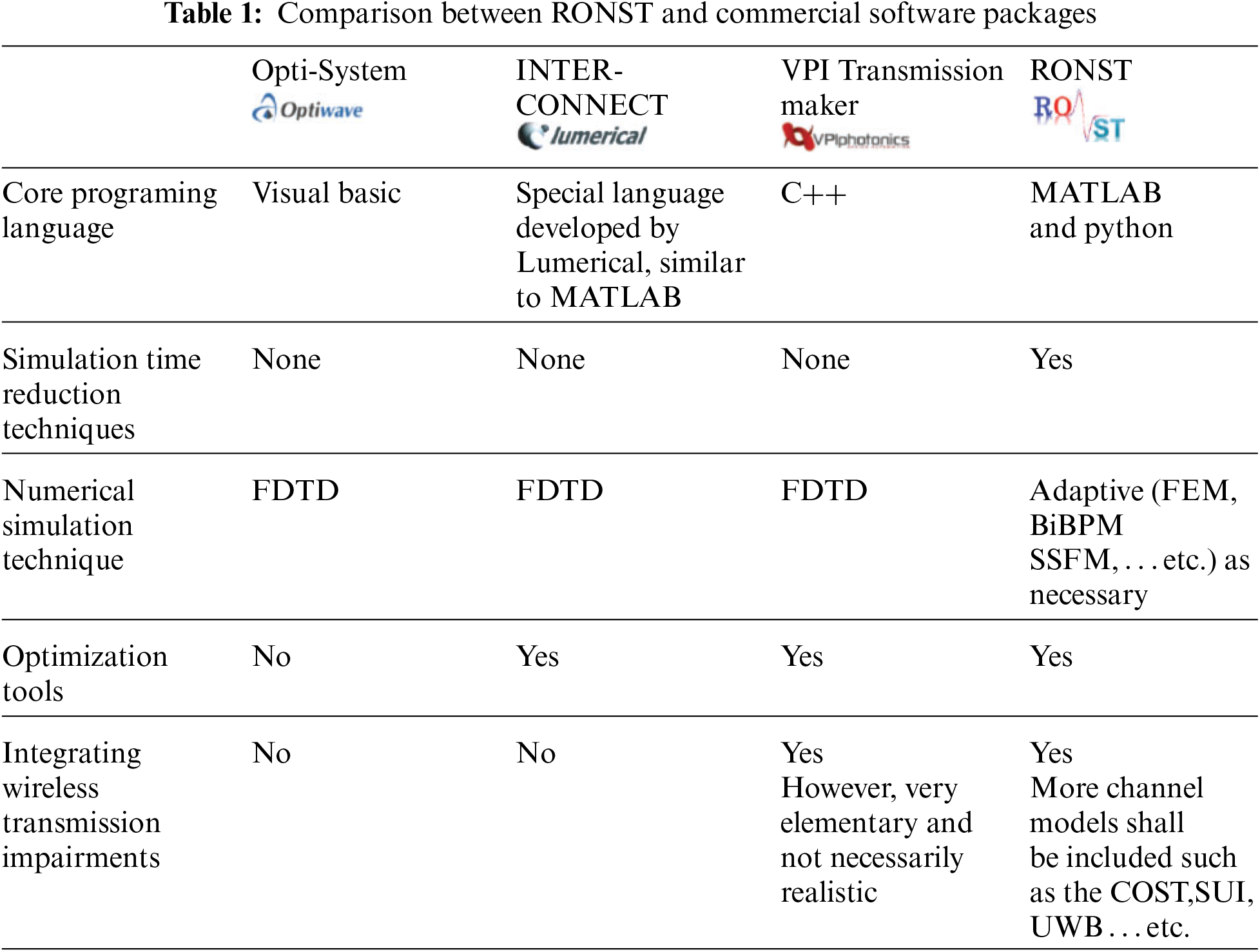
Moreover, the above simulators do not usually take into account the transmission of realistic signals. Even those which deal with transmission standards like WiFi, WiMax, LTE and LTE-A, do not assume a realistic signal.
It is important in the development process of any simulation and modeling SW to ensure the reliability of the developed package. Several metrics can be used as a reliable measurement depending on the inspector's performance evaluation viewpoint. In what follows are some of these reliability metrics that are considered in the proposed CAD tool,
1. The accuracy of the results obtained in comparison with those obtained from experimental set-ups representing real world applications
2. The simulation speed of a typical system model of moderate complexity compared to other similar SW simulation tools
3. The diversity of the library components, analysis and visualization tools
4. The integrity with other software packages for the purpose of co-simulation
5. Inter-operability of the developed SW under different operating system environments
4 Simulation Results and Discussion
The experiments have been designed and performed with the aid of the necessary hardware tools and apparatus. These experiments simulated real-life scenarios and were compared with simulation results obtained from RONST to verify the results and adjust any fitting parameters.
In this experiment, we have measured the s-parameters as a representation for the transfer function of the whole system implemented in Fig. 4. The instruments’ details of this setup are provided in Tab. 2. As shown in Fig. 5, a simulation setup was built by RONST based on the specifications of the listed components. The experimental setup aims to assess the capability of the RONST simulator to give results close to the experimental outputs.
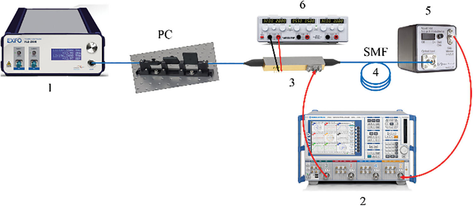
Figure 4: Schematic diagram used for measuring the transfer function of the optoelectronic link. PC: polarization controller. It is used to align the laser light polarization with the electro-optical modulator. SMF: single mode fiber
The previous setup was performed using the following scenario. The optical wavelength,
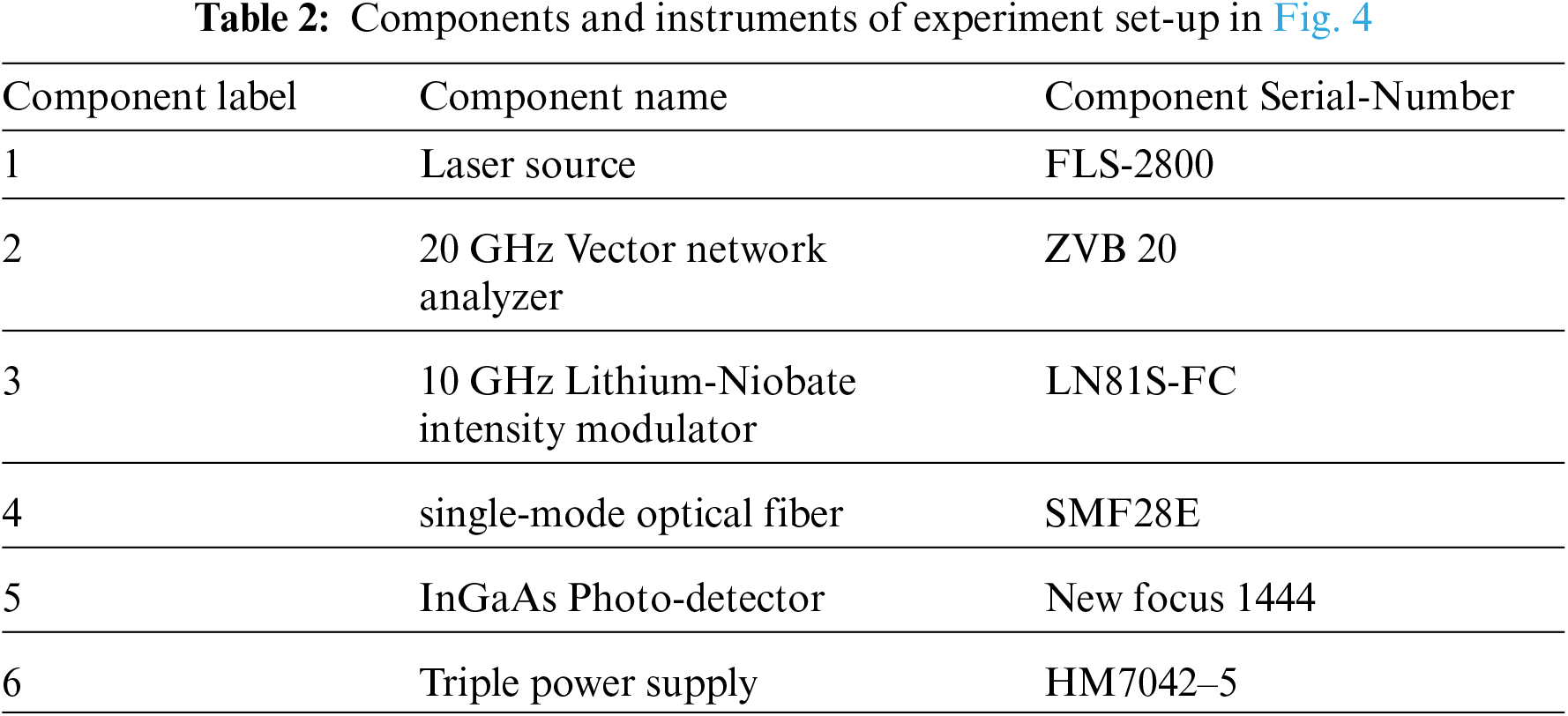
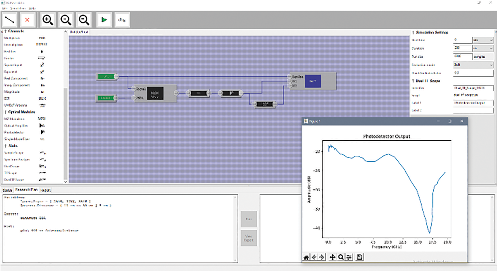
Figure 5: An UWBoF module implemented by RONST, inset: the transfer function variation of the photodetector output over the frequency of the input RF signal
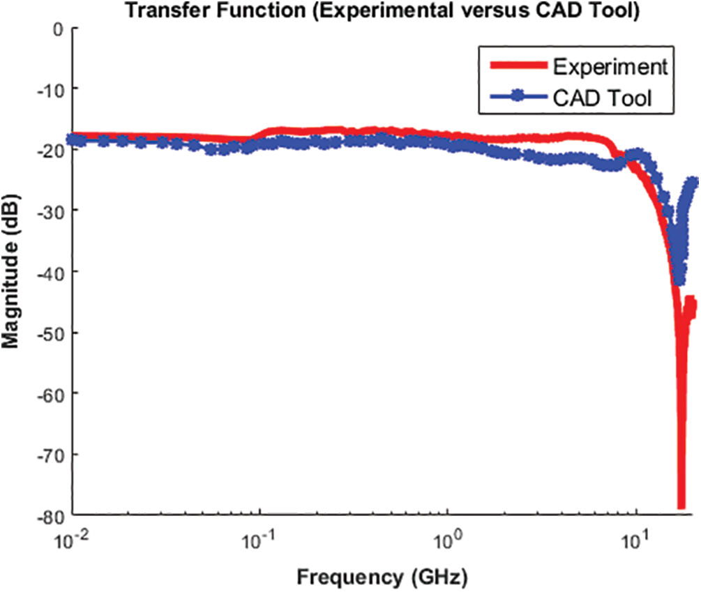
Figure 6: The magnitude of the link transfer function at the output of photodetector vs. the frequency of RF signal
4.2 Bit Error Rate vs. Input Power
The variation in the input power of a laser source at 1550 nm, has been controlled by adding attenuators with different values at the input of an optical fiber,
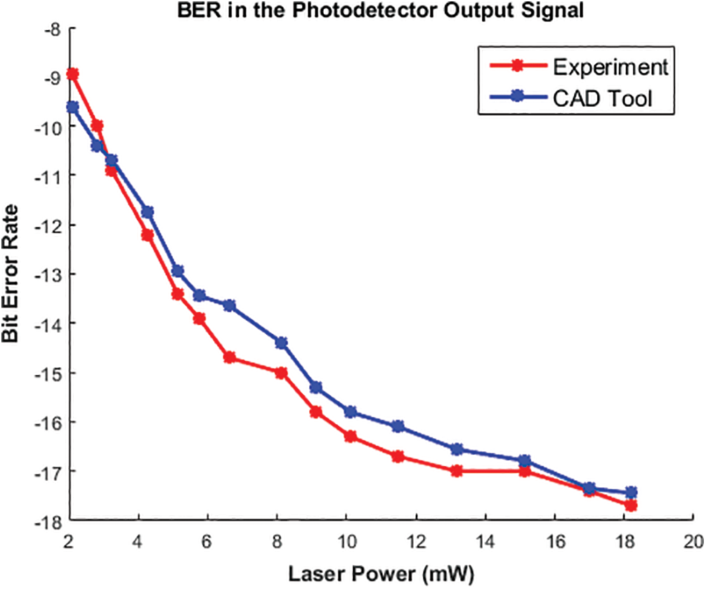
Figure 7: The BER at the photodetector output signal vs. the input power of a laser source
4.3 Bit Error Rate vs. Fiber Length
The effect of the optical fiber length over the BER measurements has been studied. The single-mode fiber length was changed for four distances,
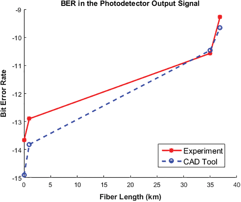
Figure 8: The bit error rate in the photodetector output signal vs. the optical fiber length
We have designed and implemented an efficient Tx and Rx antennas over three separation distances,
In addition, Fig. 11 shows the updated results for the BER vs. input power of the laser after considering the previous setup of antennas. It can be seen that RONST is able to depict the increase in the bit error rate arising from the increase in the channel length between the Tx and Rx antennas.
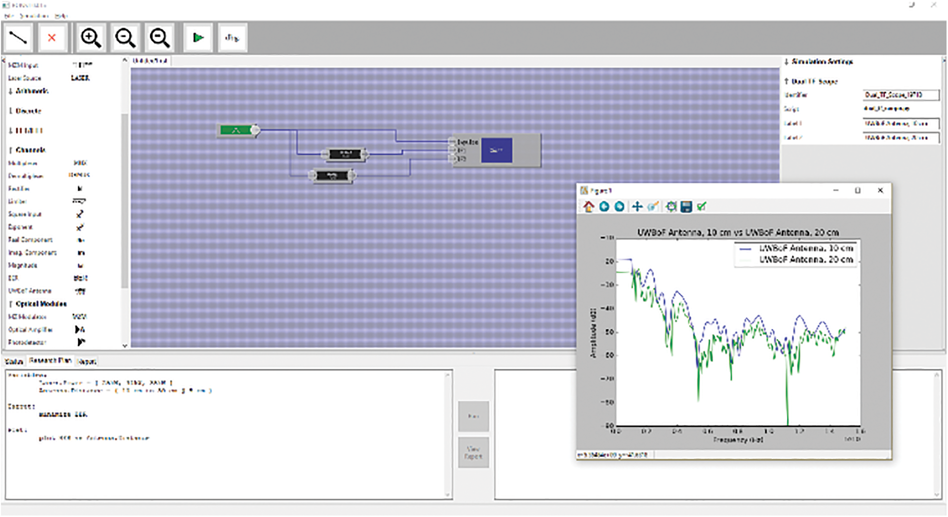
Figure 9: RONST interface shows the response of Tx and Rx antennas at separation distances of 10 cm and 20 cm
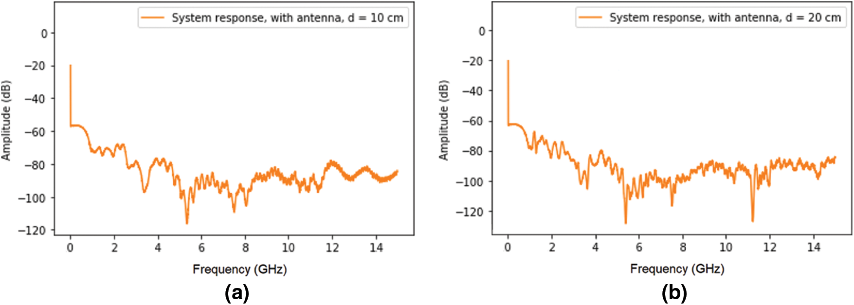
Figure 10: The simulation results for the system transfer function over the input frequency of RF signal after considering Tx-Rx antennas with a separation distance. (a) 10 cm and (b) 20 cm
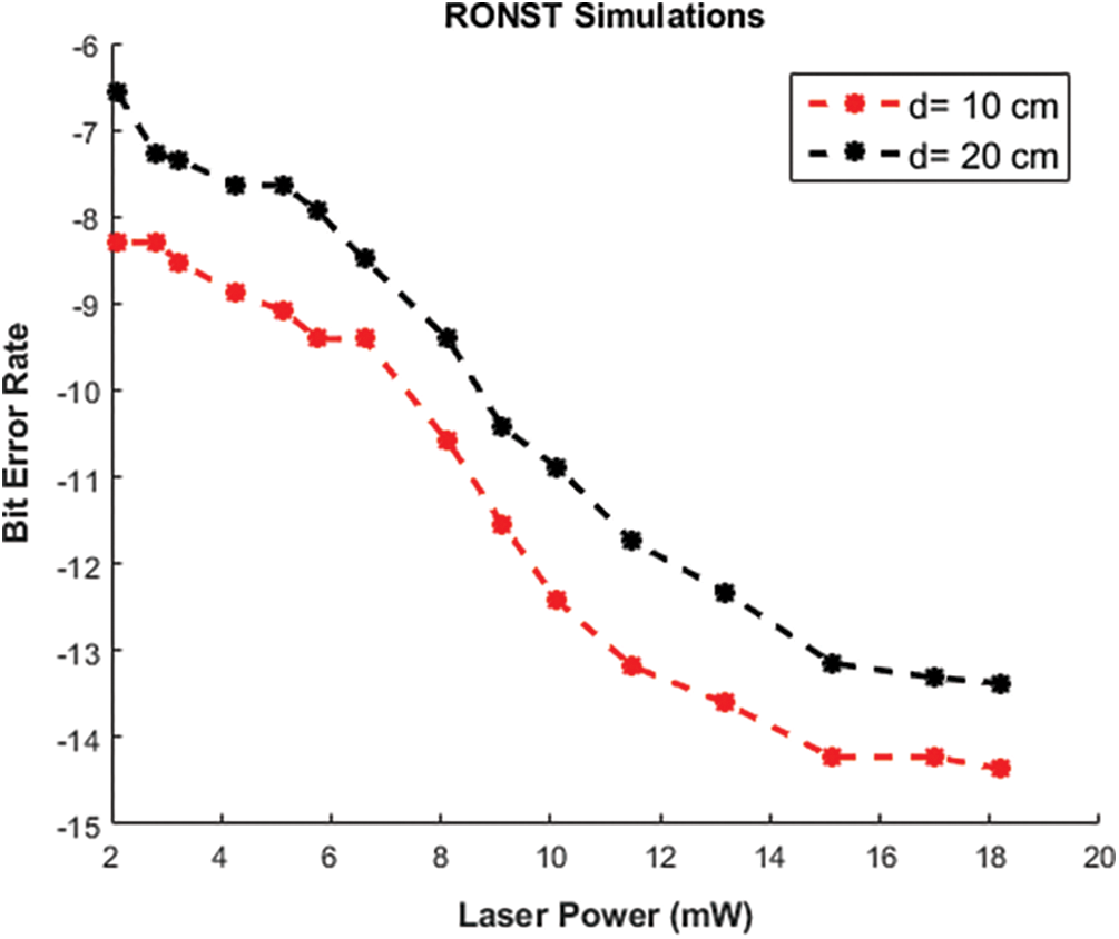
Figure 11: The bit error rate vs. the input power of a laser source after considering Tx-Rx antennas at distances, 10 cm and 20 cm
RONST is a proposed CAD tool that strongly influences various aspects of the public research community and the telecommunications sector. On the research community level, RONST will provide a low-cost alternative to the various and incompatible simulators in the fields of optical and RF engineering. Therefore, the unique features offered by RONST will encourage the research community to engage in the newly emerging field of microwave photonics. On the telecommunications service provider's level, RONST offers better services to millions of end-users through the optimal design of their last hop connections using the developed software package and its associated modules. This leads to consumers’ satisfaction and thus; increases revenues and reduces users’ complaints. This paper introduces a brief description of RONST numerical techniques, besides the background mathematical analysis. Several approaches have been integrated to cover the physical phenomena of such optical-wireless systems. For the first time, the FEM-based NI-BiBPM approach is developed to reduce the dimensionality of the solution and hence, the computational resources. Mathematical techniques, such as BSA and the lumping method have been adopted to speed up the computation process. The RONST simulations have been validated by the experimental results of an UWBoF system achieving a very good agreement and reliable expectations of the behavior of such systems.
Acknowledgement: The authors would like to thank the Opto-Nano-Electronics laboratory (ONE Lab), Cairo University, and National Telecom Regulatory Authority (NTRA), Egypt.
Funding Statement: The authors received a funding for this study by National Telecom Regulatory Authority (NTRA), Egypt “https://www.tra.gov.e.g.,/en/”
Conflicts of Interest: The authors whose names are listed immediately below certify that they have not affiliations with or involvement in any organization or entity with any financial interest (such as honor-aria; educational grants; participation in speakers’ bureaus; membership, employment, consultancies, stock ownership, or other equity interest; and expert testimony or patent-licensing arrangements), or non-financial interest (such as personal or professional relationships, affiliations, knowledge or beliefs) in the subject matter or materials discussed in this manuscript.
1. B. E. A. Saleh and M. C. Teich, Fundamentals of Photonics, 3rd ed., Hoboken, New Jersey, USA: John Wiley and Sons Inc., 2019. [Google Scholar]
2. S. N. Mahmood, A. J. Ishak, A. Ismail, A. C. Soh, Z. Zakaria et al., “ON-Off body ultra-wideband (UWB) antenna for wireless body area networks (WBANA review,” IEEE Access, vol. 8, pp. 150844–150863, Aug. 2020. [Google Scholar]
3. X. Chen and S. Kiaei, “Monocycle shapes for ultra wideband system,” IEEE International Symposium on Circuits and Systems, vol. 1, pp. 26–29, May 2002. [Google Scholar]
4. M. Renzo, D. Leonardis, F. Graziosi and F. Santucci, “Performance analysis and optimization of Tc-DTR IR-UWB receivers over multipath fading channels with tone interference,” IEEE Transactions on Vehicular Technology, vol. 60, no. 7, pp. 3076–3095, Sep. 2011. [Google Scholar]
5. M. Ilyas, O. N. Ucan, O. Bayat, X. Yang and Q. H. Abbasi, “Mathematical modeling of ultra wideband in vivo radio channel,” IEEE Access, vol. 6, pp. 20848–20854, Apr. 2018. [Google Scholar]
6. M. Ghavami, L. B. Michael and R. Kohno, Ultra Wideband Signals and Systems in Communication Engineering, 2nd ed., West Sussex, Southern Gate, Chichester, UK: Wiley, 2007. [Google Scholar]
7. U.S. Federal Communications Commission, “Revision of part 15 of the commission's rules regarding ultra-wideband transmission systems,” U.S. Federal Commun. Commission, Washington, DC, USA, Tech. Rep. FCC 02–48, Apr. 2002. [Google Scholar]
8. C. Saha, J. Y. Siddiqui, A. P. Freundorfer, L. A. Shaik and Y. M. M. Antar, “Active reconfigurable ultra-wideband antenna with complementary frequency notched and narrowband response,” IEEE Access, vol. 8, pp. 100802–100809, May 2020. [Google Scholar]
9. X. T. Yuan, W. He, K. D. Hong, C. Z. Han, Z. Chen et al., “Ultra-wideband MIMO antenna system with high element-isolation for 5G smartphone application,” IEEE Access, vol. 8, pp. 56281–56289, Mar. 2020. [Google Scholar]
10. F. Zeng and J. Yao, “An approach to ultra wideband pulse generation and distribution over optical fiber,” IEEE Photonics Technology Letters, vol. 18, no. 7, pp. 823–825, Apr. 2006. [Google Scholar]
11. R. R. Lopez, J. B. Jensen, A. C. Jambrina, X. Yu, S. Pivnenko et al., “Enhanced bit rate-distance product impulse radio ultra-wideband over fiber link,” Microwave and Optical Technology Letters, vol. 52, no. 7, pp. 1697–1680, Jul. 2010. [Google Scholar]
12. S. T. Abraha, C. Okonkwo, H. Yang, D. Visani, Y. Shi et al., “Performance evaluation of IR-UWB in short-range fiber communication using linear combination of monocycles,” Journal of Lightwave Technology, vol. 29, no. 8, pp. 1143–1151, Apr. 2011. [Google Scholar]
13. P. Cao, X. Hu, J. Wu, L. Zhang, X. Jiang et al., “Photonic generation of 3-D UWB signal using a dual-drive mach-zehnder modulator,” IEEE Photonics Technology Letters, vol. 26, no. 14, pp. 1434–1437, Jul. 2014. [Google Scholar]
14. T. B. Gibbon, X. Yu, R. Gamatham, N. G. Gonzalez, R. Rodes et al., “3.125 Gb/s impulse radio ultra-wideband photonic generation and distribution over a 50 km fiber with wireless transmission,” IEEE Microwave and Wireless Components Letters, vol. 20, no. 2, pp. 127–129, Feb. 2010. [Google Scholar]
15. J. Yao, F. Zeng and Q. Wang, “Photonic generation of ultra wideband signals,” Journal of Lightwave Technology, vol. 25, no. 11, pp. 3219–3235, ISSN 0733-8724, Nov. 2007. [Google Scholar]
16. M. Bolea, J. Mora, B. Ortega and J. Capmany, “Flexible monocycle UWB generation for reconfigurable access networks,” IEEE Photonics Technology Letters, vol. 22, no. 12, pp. 878–880, ISSN 1041-1135, May 2010. [Google Scholar]
17. H. Feng, M. P. Fok, S. Xiao, J. Ge, Q. Zhou et al., “A reconfigurable high-order UWB signal generation scheme using RSOA-MZI structure,” IEEE Photonics Journal, vol. 6, no. 2, pp. 1–7, Apr. 2014. [Google Scholar]
18. M. Abtahi, J. Magne, M. Mirshafiei, L. A. Rusch and S. LaRochelle, “Generation of power-efficient FCC-compliant UWB waveforms using FBGs: Analysis and experiment,” Journal of Lightwave Technology, vol. 26, no. 5, pp. 628–635, Mar. 2008. [Google Scholar]
19. J. Lee, Y. M. Chang and J. H. Lee, “UWB doublet pulse generation using the combination of parametric amplification and cross phase modulation,” in Int. Photonics Conf. (IPC) IEEE, San Francisco, CA, USA, Sept. 2012. [Google Scholar]
20. M. Mirshafiei, M. Abtahi, P. Larochelle and L. A. Rusch, “Pulse shapes that outperform traditional UWB antenna/waveform combinations,” in Global Telecommunications Conf. (GLOBECOM) IEEE, Miami, FL, USA, Dec. 2010. [Google Scholar]
21. H. Taki, S. Azou, A.Hamie, A. A. Al-Housseini, A. Alaeddine et al., “On optimizing the operating conditions of a mach-zehnder modulator for IR-UWB over fiber transmission,” in 5th Int. Conf. of Digital Information and Communication Technology and its Applications (DICTAPpp. 169–172, April 29-May 1, 2015. [Google Scholar]
22. M. Shehata, H. Mostafa and Y. Ismail, “Closed-form expressions and bounds for the signal to noise ratio in IR-UWBoF systems,” IEEE Photonics Technology Letters, vol. 29, no. 6, pp. 507–510, Mar. 2017. [Google Scholar]
23. M. Shehata, H. Mostafa and Y. Ismail, “Accurate closed-form expressions for the bit rate-wireless transmission distance relationship in IR-UWBoF systems,” IEEE Communications Letters, vol. 21, no. 10, pp. 2138–2141, Oct. 2017. [Google Scholar]
24. M. Shehata, H. Mostafa and Y. Ismail, “On the theoretical limits of the power efficiency of photonically generated IR-UWB waveforms,” Journal of Lightwave Technology, vol. 36, pp. 2017–2023, 2017. [Google Scholar]
25. M. Shehata, M. Sameh and H. Mostafa “Dual notched band quad-element MIMO antenna with multitone interference suppression for IR-UWB wireless applications,” IEEE Transactions on Antenna and Propagation, vol. 66, no. 11, pp. 5737–5746, Nov. 2018. [Google Scholar]
26. M. Shehata, M. Sameh and H. Mostafa “A generalized framework for the performance evaluation of microwave photonic assisted IR-UWB waveform generators,” IEEE Systems Journal, vol. 13, no. 4, pp. 3724–3734, Dec. 2019. [Google Scholar]
27. G. P. Agrawal, Nonlinear Fiber Optics, 4th ed., Burlington, MA, USA, Jul. 2006. [Google Scholar]
28. T. J. Smy, S. A. Stewart, J. G. N. Rahmeier and S. Gupta, “FDTD simulation of dispersive meta-surfaces with lorentzian surface susceptibilities,” IEEE Access, vol. 8, pp. 83027–83040, May 2020. [Google Scholar]
29. H. Choi, Y. H. Kim, J. W. Baek and K. Y. Jung, “Accurate and efficient finite-difference time-domain simulation compared with CCPR model for complex dispersive media,” IEEE Access, vol. 7, pp. 160498–160505, Nov. 2019. [Google Scholar]
30. S. D. Gedney, Introduction to the Finite-Difference Time-Domain Method for Electromagnetics (Synthesis Lectures on Computational Electromagnetics), 1st ed., San Rafael, CA, USA: Morgan & Claypool Publishers, Jan. 2011. [Google Scholar]
31. M. M. Tamasala, S. Shikhantsov, M. Deruyck, E. Tanghe, D. Plets et al., “Combined ray-tracing/FDTD and network planner methods for the design of massive MIMO networks,” IEEE Access, vol. 8, pp. 206371–206387, Nov. 2020. [Google Scholar]
32. J. Chen, J. Tan, X. Yu and H. Shi, “Using WCS-FDTD method to study the plasma frequency selective surface,” IEEE Access, vol. 7, pp. 152473–152477, Oct. 2019. [Google Scholar]
33. R. Chen, L. Kuang, Z. Zheng and Q. H. Liu, “A novel transformation optics-based FDTD algorithm for fast electromagnetic analysis of small structures in a large scope,” IEEE Access, vol. 7, pp. 124750–124758, Aug. 2019. [Google Scholar]
34. A. C. Polycarpou, in Introduction to the Finite Element Method in Electromagnetics, Computational Electromagnetics, San Rafael, CA, USA: Morgan and Claypool Publishers, 2006. [Google Scholar]
35. A. Anees and L. Angermann, “Time domain finite element method for Maxwell's equations,” IEEE Access, vol. 7, pp. 63852–63867, May 2019. [Google Scholar]
36. R. Hong, K. Chen, X. Hou, Q. Sun, N. Liu et al., “Mixed finite element method for full-wave simulation of bio-electromagnetism from DC to microwave frequencies,” IEEE Transactions on Biomedical Engineering, vol. 67, no. 10, pp. 2765–2772, Jan. 2020. [Google Scholar]
37. H. Xie, J. Song, Y. Zhong and C. Gu, “Kalman filter finite element method for real-time soft tissue modeling,” IEEE Access, vol. 8, pp. 53471–53483, Mar. 2020. [Google Scholar]
38. Y. I. Abdelhak, A. M. Said, N. F. Areed and S. S. Obayya, “Efficient scalar bidirectional beam propagation analysis for photonic devices with circular symmetry,” IEEE Photonics Technology Letters, vol. 33, no. 1, pp. 43–46, Jan. 2021. [Google Scholar]
39. P. L. Ho and Y. Y. Lu, “A stable bidirectional propagation method based on scattering operators,” IEEE Photonics Technology Letters, vol. 13, no. 12, pp. 1316–1318, Dec. 2001. [Google Scholar]
40. H. El-Refaei, D. Yevick and I. Betty, “Stable and non-iterative bidirectional beam propagation method,” IEEE Photonics Technology Letters, vol. 12, no. 4, pp. 389–391, Apr. 2000. [Google Scholar]
41. O. C. Zienkiewicz and R. L. Taylor, in The Finite Element Method, Oxford, UK: Butterworth-Heinemann, 2000. [Google Scholar]
42. E. Deadman, N. J. Higham and R. Ralha, “Blocked schur algorithms for computing the matrix square root,” in 11th Int. Conf. of Applied Parallel and Scientific Computing, Helsinki, Finland, vol. 7782, pp. 171–182, Jun. 2012. [Google Scholar]
43. N. J. Higham, in Functions of Matrices: Theory and Computation, Chapter 6: Matrix Square Root, Philadelphia, PA, USA: SIAM, 2008. [Google Scholar]
44. J. M. Jarem and P. P. Banerjee, “Scalar EM beam propagation in inhomogeneous media,” Electrical and Computer Engineering Faculty Publications, 244, Taylor and Francis, pp. 1–40, 2011. [Google Scholar]
45. H. E. Kotb, M. A. Abdelalim, K. J. Bock and H. Anis, “Peak power optimization of optical pulses using low-doped gain-medium in femtosecond fiber laser,” Journal of Lightwave Technology, vol. 31, no. 13, pp. 2230–2236, 2013. [Google Scholar]
46. H. E. Kotb, M. A. Abdelalim and H. Anis, “An efficient semi-vectorial model for all-fiber mode-locked femtosecond lasers based on nonlinear polarization rotation,” IEEE Journal of Selected Topics in Quantum Electronics, vol. 20, no. 5, pp. 1100809(1–92014. [Google Scholar]
47. H. E. Kotb, M. A. Abdelalim and H. Anis, “Effect of narrow spectral filter position on the characteristics of active similariton mode-locked femtosecond fiber laser,” Optics Express, vol. 23, no. 23, pp. 29660–29674, 2015. [Google Scholar]
48. H. E. Kotb, M. A. Abdelalim and H. Anis, “Generalized analytical model for dissipative soliton in all normal dispersion mode locked fiber laser,” IEEE Journal of Selected Topics in Quantum Electronics, vol. 22, no. 2, pp. 1100209(1–92016. [Google Scholar]
49. M. A. Abdelalim, H. E. Kotb, E. Joseph, A. M. Othman and H. Anis, “Experimental and numerical demonstration on the gain and power saturation of Yb-doped double-clad fiber amplifiers in multi-wavelength CW and ultrafast pulsed operation,” IEEE Photonics Journal, vol. 10, no. 1, pp. 7100212 (1–132018. [Google Scholar]
50. H. E. Kotb, M. A. Abdelalim and H. Anis, “Effect of mode locking technique on the filtering bandwidth limitation in all normal dispersion femtosecond fiber laser,” SPIE Proc., Fiber Lasers XI: Technology, Systems, and Applications, Vol. 8961, pp. 89613A(1–112014. [Google Scholar]
51. R. Hui, M. O'Sullivan, Fiber Optic Measurement Techniques, 1st ed., Burlington, MA, USA: Academic Press, Elsevier, 2009. [Google Scholar]
 | This work is licensed under a Creative Commons Attribution 4.0 International License, which permits unrestricted use, distribution, and reproduction in any medium, provided the original work is properly cited. |