DOI:10.32604/cmc.2022.023442
| Computers, Materials & Continua DOI:10.32604/cmc.2022.023442 | |
| Article |
Continuous Tracking of GPS Signals with Data Wipe-Off Method
Department of Communications, Navigation and Control Engineering, National Taiwan Ocean University, Keelung, 202301, Taiwan
*Corresponding Author: Dah-Jing Jwo. Email: djjwo@mail.ntou.edu.tw
Received: 08 September 2021; Accepted: 26 October 2021
Abstract: The decentralized pre-filter based vector tracking loop (VTL) configuration with data wipe-off (DWO) method of the Global Positioning System (GPS) receiver is proposed for performance enhancement. It is a challenging task to continuously track the satellites’ signals in weak signal environment for the GPS receiver. VTL is a very attractive technique as it can provide tracking capability in signal-challenged environments. In the VTL, each channel will not form a loop independently. On the contrary, the signals in the channels of VTL are shared with each other; the navigation processor in turn predicts the code phases. Thus, the receiver can successfully track signals even the signal strength from individual satellite is weak. The tracking loop based on the pre-filter provides more flexible adjustment to specific environments to reduce noise interference. Therefore, even if the signals from some satellites are very weak the receiver can track them from the navigation results based on the other satellites. The navigation data, which contains information necessary to perform navigation computations, are binary phase-shift keying (BPSK) modulated onto the GPS carrier phase with the bit duration of 20 ms (i.e., 50 bits per second) for the GPS L1 C/A signals. The coherent integration interval can be extended for improved tracking performance in signal-challenged environment. However, tracking accuracy is decreased by possible data bit sign reversal. The DWO algorithm can be employed to remove the data bit in I and Q correlation values so as to avoid energy loss due to bit transitions when the integration interval of the correlator is extended over 20 ms under the low carrier-to-noise ratio (C/No) environments. The proposed method has an advantage to provide continuous tracking of signals and obtain improved navigation performance. Performance evaluation of the tracking capability as well as positioning accuracy will be presented.
Keywords: Global positioning system (GPS); vector tracking loop; pre-filter; data wipe-off; weak signal
Traditional Global Positioning System (GPS) or other Global Navigation Satellite System (GNSS) [1–6] receivers track signals from different satellites independently. Each tracking channel measures the pseudorange and range rate, respectively, and then sends them to the navigation processor to solve for the user's position, velocity, clock bias and drift (PVT). The signal tracking modulo tries to adjust the local signal to synchronize the local phases with the received ones from satellites. As one of the most vulnerable parts of a receiver, the carrier and code tracking loops play a key role in a GPS receiver.
The traditional scalar tracking loop (STL) is composed of the correlator, discriminator, loop filter, and numerically control oscillator (NCO) in each channel. The intermediate frequency (IF) signal is correlated with internally generated replica signal, and the output of correlator consists of in-phase (I) and quadrature-phase (Q) components via integrate-and-dump operation. The traditional STL processes signals from each satellite separately and the discriminators are employed to measure the code phase error and carrier frequency error, which are passed to navigation filter and through loop filter to control NCO. The STL processes signals from each satellite separately. Specifically, a delay lock loop (DLL) is used to track the code phase of the incoming pseudorandom code and a carrier tracking loop, such as a frequency lock loop (FLL) or a phase lock loop (PLL), is used to track the carrier frequency or phase. The tracking results from different channels are then combined to estimate the navigation solutions. The drawback of STL is that it neglects the inherent relationship between the navigation solutions and the tracking loop status. In that sense, a STL is more like an open loop system and provides poor performance when scintillation, interference, or signal outages occur.
Several researchers have recently studied a vector tracking loop (VTL) [7–11], such as a vector delay lock loop (VDLL) and a vector frequency lock loop (VFLL), and the combination of both, called VDFLL, to obtain an improved tracking performance in GPS receiver. Vector tracking loops integrate the tracking loops and navigation processor, such that each tracking loop update is also based on information from other tracking loops. For the VTL architectures, the tasks of signal tracking and navigation state estimation are no longer separate processes. The VTL architectures provide several important advantages as compared to the STL ones. They differ from the traditional STL in that the task of navigation solutions, code tracking and carrier tracking loops for all satellites are combined into one loop. The VTL provides a deep level of integration between signal tracking and navigation solutions in a GPS receiver and results in several important improvements over the traditional STL such as increased interference immunity, robust dynamic performance, and the ability to operate at low signal power and bridge short signal outages [12–15]. In the VTL structure, all channels are processed together in one processor which is typically an estimator, such as extended Kalman filter (EKF) [16,17] or unscented Kalman filter (UKF) [18,19] to provide an estimation of signal parameters for all satellites in view and user PVT solutions based on both current and previous measurements from all satellites.
To achieve improved tracking performance in signal-challenged environment such as low C/No level, the coherent integration interval in a GPS receiver has to be increased. However, the tracking accuracy of a weak signal is decreased by the possible data bit sign reversal every 20 ms to the integration interval for the GPS L1 C/A signals. The data wipe-off (DWO)/data wiping techniques [20–22] can be incorporated into the VTL of a GPS receiver to improve the tracking threshold. The DWO algorithm enables longer coherent integration time by removing the 50 Hz navigation data from the received signal. The technique is employed on the basis of pre-detection method to detect data bit sign reversal to extend the coherent integration interval over 20 ms. Different levels of signal quality, e.g., carrier-to-noise (C/No), will influence I and Q values in the same coherent integration interval. Increase of integration interval will increase the anti-interference ability. In the case of signal-challenged environment, performance improvement can be made by extending coherent integration interval. The DWO algorithm can be employed to remove the data bit in I and Q correlation values and to avoid energy loss due to bit transitions when the integration interval of the correlator is extended over 20 ms in low C/No levels. The VTL based on the pre-filter offers better flexibly to adjust and better anti-jamming than that based on the discriminator. The measurement of the pre-filter is the I and Q components, which are highly nonlinear to the states of for pre-filter. The DWO algorithm based on the carrier phase discriminator is used to estimate the phase and to remove effect of navigation data to avoid the navigation data bit phase reversal that might lead to estimation divergence.
This paper presents the continuous tracking and accuracy improvement of a GPS receiver using the data wipe-off techniques. The remaining of this paper is organized as follows. In Section 2, preliminary background on the pre-filter based vector tracking loop is reviewed. The data wipe-off method using the carrier phase discriminator is discussed in Section 3. In Section 4, the navigation filter design is presented. In Section 5, simulation experiments are carried out to evaluate the performance and effectiveness. Conclusions are given in Section 6.
2 The Pre-Filter Based Vector Tracking Loop
In a conventional GPS receiver with VTL, each channel consists of a correlator, discriminator and numerically controlled oscillator (NCO), where the loop filter is removed. The code loop NCO in the STL is replaced by the estimated user positions to control the update of the local code. The VTL based on the discriminator utilizes the output of the nonlinear discriminator. The Doppler frequencies and the pseudoranges are calculated from the estimated user position and velocity from the output of navigation filter. The VTL outputs of each channel are used as the measurement of the navigation filter, which then provides feedback to NCO. The navigation filter can be an EKF or an UKF, employed to estimate the navigation state PVT of the receiver. The error signals arise from the estimated user positions and the satellite positions calculated by the ephemeris. When one channel experiences interference or signal outages in the VTL, the information from other satellites can be used estimate the status of this channel.
Some relations for the code phase
and the carrier Doppler frequency and the pseudorange rate are related by
where c is the speed of light;
where
The Doppler frequency error can be written as
where
The system configuration is this paper employed is the decentralized pre-filter based vector tracking loop, where each channel consists of a correlator, pre-filter and NCO, shown as in Fig. 1.
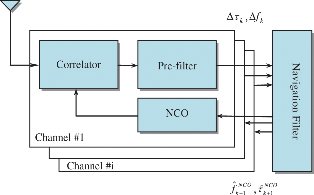
Figure 1: System configuration of the pre-filter based vector tracking loop
The front-end converts the RF GPS signals to intermediate frequency signal (
The local oscillator-generated signals in the in-phase and quadrature branches of correlator outputs are, respectively, given by
where P is the signal power; D is the navigation data bit; g is the PRN code;
and furtherly simplified to
Similarly, an approximation of the accumulated quadrature-phase signal component is
The correlation function of the PRN sequences between the local prompt code and received spreading code is
where the code phase error
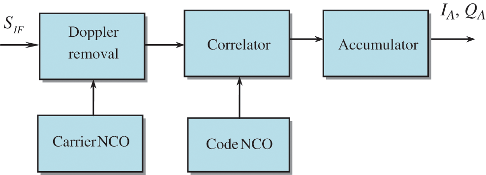
Figure 2: Flowchart for generation of in-phase (IA) and quadrature-phase (QA) correlator outputs
The I and Q correlator outputs for Channel i are utilized as the measurements for the pre-filter, represented as
where
The models involved include a linear system dynamic model and a nonlinear measurement model given as
There are four parameters (
the pre-filter dynamics takes the form
where
In this paper, an UKF is employed for each pre-filter in the VTL, where the measurement vector is composed of the early, prompt, and late components of in-phase and quadrature-phase correlator outputs:
The nonlinear relation of the measurements and state variables are related by
where
3 The Data Wipe-Off Method Based on Carrier Phase Discriminator
For performance improvement, a DWO algorithm is presented on the basis of pre-detection method to avoid the energy decrease by possible data bit sign reversal. Two common DWO algorithms are: (1) the energy-based bit estimation algorithm; (2) the carrier phase discriminator based algorithm. The DWO method based on the carrier phase discriminator is incorporated into the GPS VTL to remove the navigation data bit in I and Q correlation values. Fig. 3 shows the structure of DWO method employed in this paper. Since the measurements I and Q are high nonlinearly related to the system states, thus, the nonlinear filter algorithm possess advantages in such type of estimation problem.
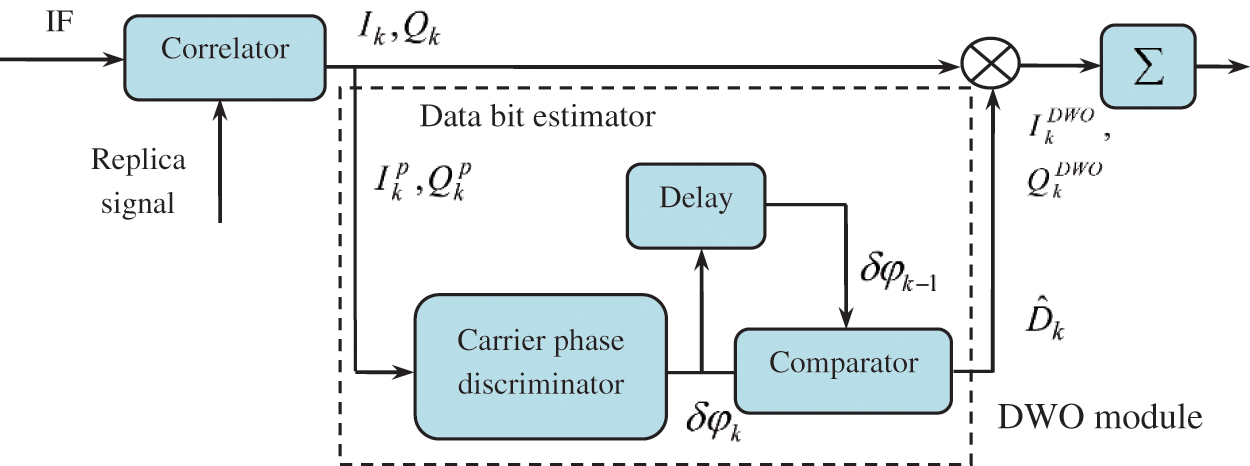
Figure 3: Block diagram for the data wipe-off (DWO) algorithm
The phase error of carrier phase discriminator is calculated by
where
where
Since the GPS possesses a 50 Hz navigation data message bit rate, the predetection integration time is usually the period of a navigation data bit, namely, 20 ms. The C/No level of the GPS with good signal power typically range from 35–55 dB-Hz, so tracking errors generally run on the lower end of the range.
Instead of decoding the navigation data, the purpose of DWO or data wiping method is employed to remove the data bit in I and Q correlation values so as to avoid energy loss due to bit transitions so as to maintain tracking under the low carrier-to-noise ratio (C/No) environments. The DWO algorithm can be employed to remove the data bit in I and Q correlation values and to avoid energy loss due to bit transitions when the integration interval of the correlator is extended over 20 ms in low C/No levels. When the integration interval ranges from 10–20 ms, the C/No of the signals that can be successfully tracked normally ranges from 32–50 dB-Hz. To further improve the sensitivity of the receiver for successful tracking at lower C/No signal levels, one important issue is to overcome the energy loss due to phase change when the integration interval is extended over 20 ms. In such case, the DWO algorithm is applicable.
To achieve higher tracking performance in weak signal environment, the coherent integration interval in a GPS receiver has to be increased. However, the tracking capability of the weak GPS signal is decreased by the possible data bit sign reversal every 20 ms to the integration interval. The DWO algorithm is presented on the basis of pre-detection method to detect data bit sign reversal to extend the coherent integration interval over 20 ms. The DWO techniques enable longer coherent integration times by removing the 50 Hz navigation data from the received signal.
When selecting extended Kalman filter as the navigation state estimator in the GPS receiver, using b and d to represent the GPS receiver clock bias and drift, the differential equation for the clock error is written as
where
The process model is assumed to be linear given by
where
Consider the user position in three dimensions, denoted by
and
respectively, where
where
where
The elements of the measurement model
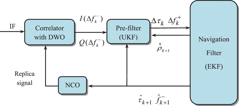
Figure 4: The pre-filter based vector tracking loop with DWO algorithm
and
Simulation experiments have been carried out to verify the effectiveness and justification of the performance. Simulation was conducted using the computer codes developed by the authors based on the Matlab® software. The commercial software Satellite Navigation Toolbox (SatNav) by GPSoft LLC [23] was utilized to generate the information used for navigation processing, such as the GPS satellite orbits/positions and thereafter, the satellite pseudoranges, carrier phase measurement for the STL receiver, required for simulation. For the VTL, the tasks of signal tracking and navigation state estimation are no longer separate processes. In such case, the pseudoranges will then be predicted based on the information from the navigation filter, which provides feedbacks for the NCO and then the correlator. The I and Q components can then be generated for the VTL simulation. It is assumed that there are 9 GPS satellites available during the simulation, with the skyplot shown as in Fig. 5.
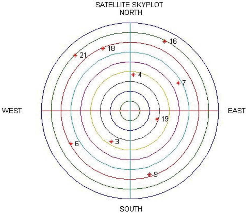
Figure 5: Configuration of the skyplot for the simulation
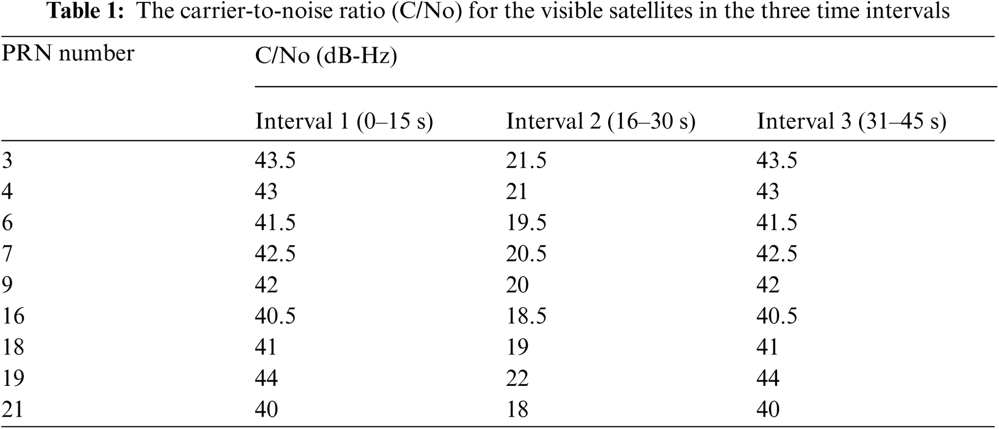
The GPS has a 50 Hz bit rate of navigation data message, thus the predetection integration time is usually the period of a navigation data bit, 20 ms. Performance comparison presented will cover three parts. The first part of investigation deals with performance comparison of VTL based on the discriminator and pre-filter with the data wipe-off algorithm. Fig. 6 shows the code phase and Doppler frequency errors based on the discriminator and pre-filter, for which the integration interval of 75 ms was utilized. In the test, the VTL based on pre-filter demonstrates improved tracking accuracy as compared to that based on discriminator. The second part deals with performance comparison for data wipe-off algorithm with two integration intervals: 1 ms and 25 ms. The GPS receiver with good signal power typically ranges from 35–55 dB-Hz, so the tracking errors generally run on the lower end of the range. The total time of simulation is 45 s, which are divided into three time intervals with 15 s for each. For testing the tracking performance in signal-challenged environment, the second time intervals are assumed to be at low C/No level.
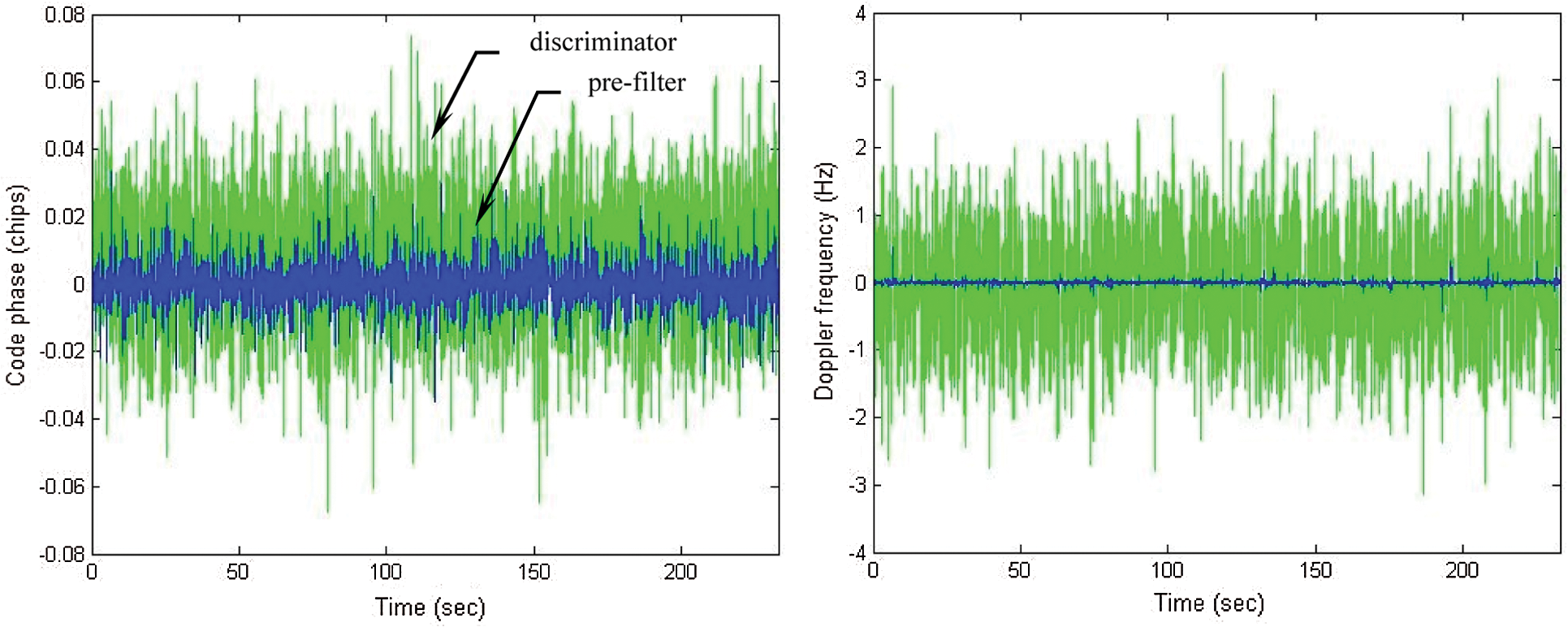
Figure 6: Code phase and Doppler frequency errors: discriminator vs. pre-filter
Tab. 1 provides the C/No values of the visible satellites in the three time intervals. The C/No levels in the first and third time intervals are set in the normal conditions for signal reception, ranging from 40–44 dB-Hz such that the tracking capability can be assured. However, in the second time interval, the C/No's are decreased to the range from 18–22 dB-Hz. Fig. 7 shows the code phase errors for four of the nine satellites selected for illustration. The receiver is not able to properly track the signals when the coherent integration interval is 1 ms. It can be seen that the blue dots represent the results based on 1 ms integration interval while the green lines denote the results when 25 ms integration interval with DWO algorithm is applied. It can be seen that application of the DWO enables the continuous tracking when longer integration interval is utilized. All the satellite signals appear to lose lock in the second time intervals without extending the time intervals. The continuous tracking of signals is assured with improved accuracy if the integration interval is extended to 25 ms under the low-quality signal environments.
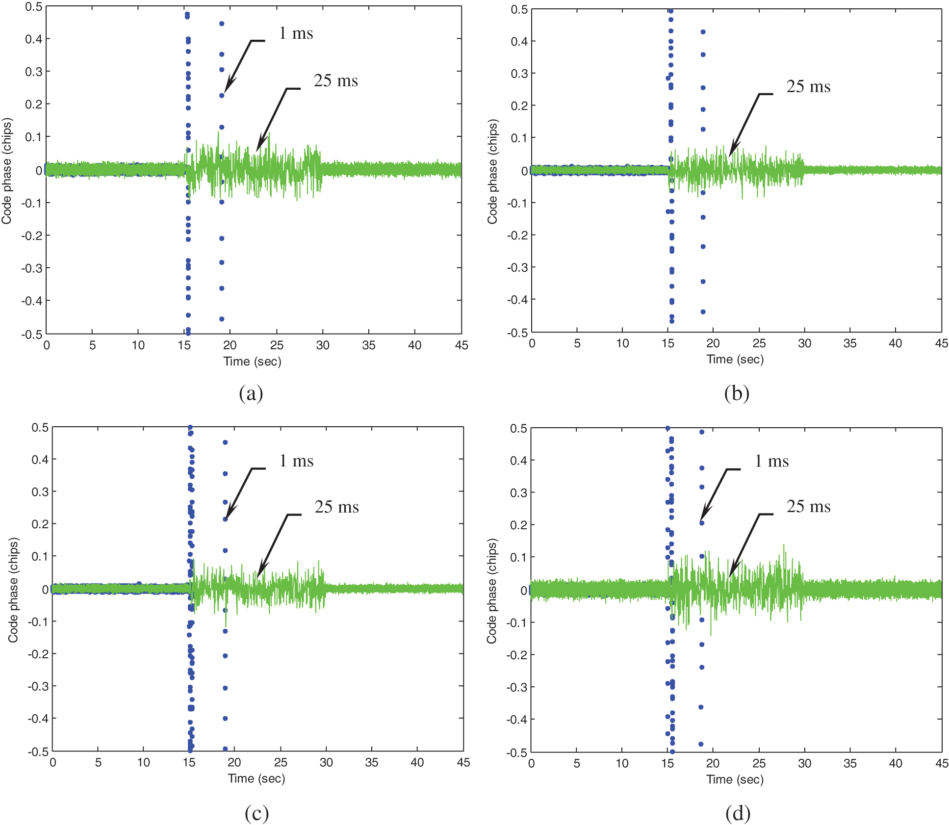
Figure 7: Code phase errors for four satellites selected for illustration (a) PRN 3 (b) PRN 6 (c) PRN 16 (d) PRN 21
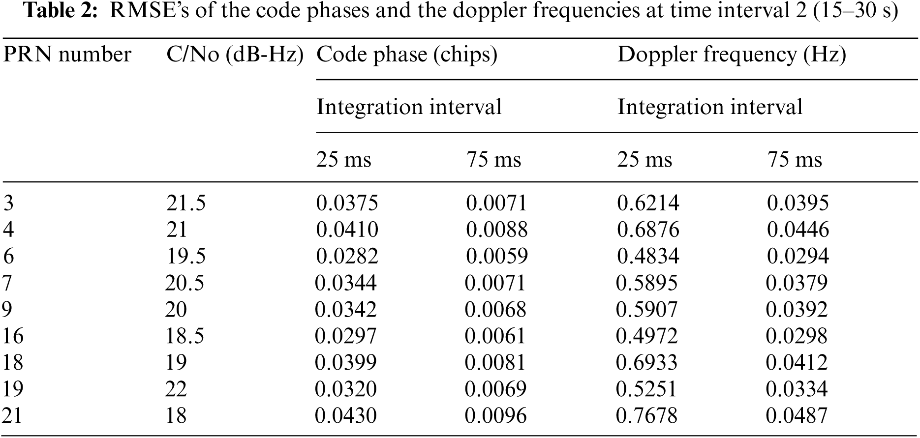
The third portion of illustration emphasizes on the performance enhancement, focusing on results at the second time interval (15–30 s), where low C/No levels are involved. Results involved include two integration intervals: 75 ms and 25 ms. Figs. 8 and 9 shows the errors of code phases and Doppler frequencies for PRN 3 and PRN 21, respectively. The results for 25 ms and 75 ms integration interval are represented by green and blue lines, respectively. Fig. 10 shows the VTL based position errors. The results based on longer integration interval leads to improved accuracy on code phase, Doppler frequency and thus the positioning accuracy. The RMSE's of the code phases and the Doppler frequencies at the second time interval are summarized in Tab. 2. It should be noticed that when all satellites are polluted, external aiding from other sensors will be helpful, such as the inertial aiding to the tracking loop. The design of ultra-tightly coupled GPS/INS integration also has good potential for overcoming this problem.
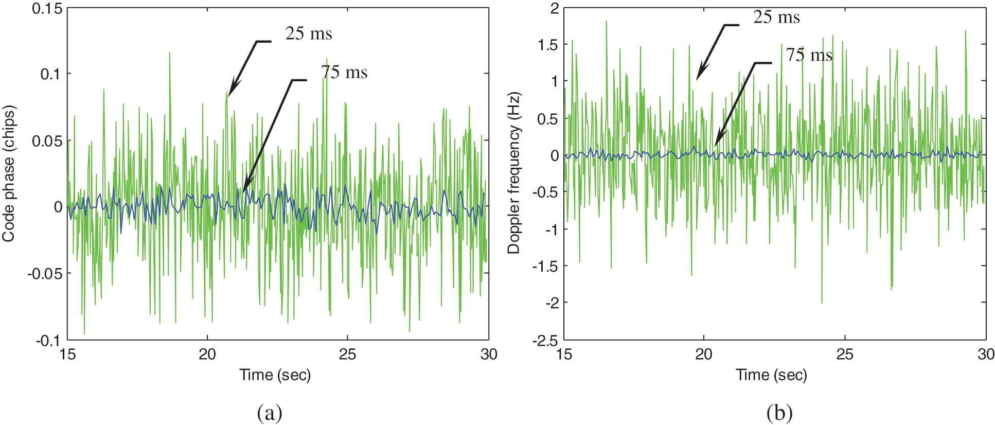
Figure 8: Code phase and Doppler frequency errors for PRN 3 (a) Code phase (b) Doppler frequency
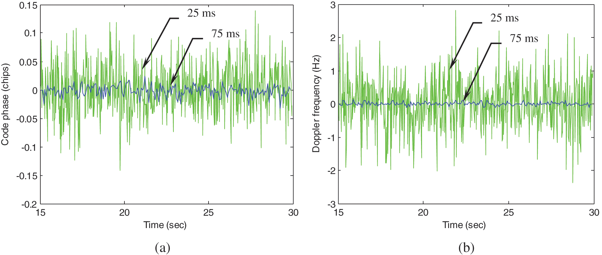
Figure 9: Code phase and Doppler frequency errors for PRN 21 (a) Code phase (b) Doppler frequency
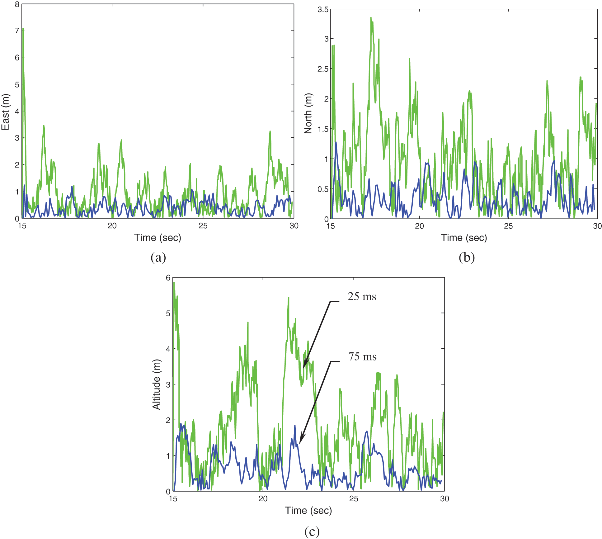
Figure 10: The VTL based position errors (a) East (b) North (c) Altitude
This paper presents the design on continuous tracking of GPS signals with data wipe-off method. The decentralized pre-filter based GPS vector tracking loop of a GPS receiver is involved to improve the tracking accuracy. The accumulated energy might be decreased by the possible data bit sign reversal every 20 ms to the integration interval for the GPS L1 C/A signals. To resolve the problem, a data wipe-off algorithm is presented on the basis of pre-detection method to detect data bit sign reversal every 20 ms. Furthermore, the tracking accuracy based on the pre-filter outperforms that based on the discriminator. Tracking accuracy of a weak GPS signal is increased by extending the coherent integration interval. Illustrated examples have been presented and results confirm that the proposed method possesses an advantage to continuously estimate the navigation states with improved tracking performance. Performance improvement can be achieved in the signal-challenged environment. It is especially useful for performance improvement under the low-quality signal environment, by extending the coherent integration interval over 20 ms. Tracking accuracies based on different integration intervals, including 1, 25, and 75 ms, are shown. Results show that the estimation accuracy increases when longer integration interval is employed. The pre-filter based VTL architecture with data wipe-off method demonstrates continuous tracking of GPS signals and shows good potential for the future designs.
Funding Statement: This work has been partially supported by the Ministry of Science and Technology, Taiwan [Grant Numbers MOST 101-2221-E-019-027-MY3 and MOST 109-2221-E-019-010].
Conflicts of Interest: The authors declare that they have no conflicts of interest to report regarding the present study.
1. E. D. Kaplan and C. J. Hegarty, Understanding GPS: Principles and Applications, Norwood, MA, USA: Artech House, Inc., 2006. [Google Scholar]
2. J. A. Farrell and M. Barth, The Global Positioning System and Inertial Navigation, New York, NY, USA: McGraw-Hill, 1999. [Google Scholar]
3. J. J. Spilker Jr., “Fundamentals of signal tracking theory,” B. W. Parkinson, J. J. Spilker Jr., P. Axelrad and P. Enge (Ed.in Global Positioning System: Theory and Applications, Washington, DC, USA: American Institute of Aeronautics and Astronautics, Inc., pp. 245–327, 1996. [Google Scholar]
4. B. Hofmann-Wellenhof, H. Lichtenegger and E. Wasle, GNSS–Global Navigation Satellite Systems, GPS, GLONASS, Galileo, and More, New York, NY, USA: Springer Wien, 2008. [Google Scholar]
5. K. Borre D. M. Akos, N. Bertelsen, P. Rinder and S. H. Jensen, A Software-Defined GPS and Galileo Receiver, Boston: Birkhauser, 2007. [Google Scholar]
6. T. Zhou, B. Lian, S. Yang, Y. Zhang and Y. Liu, “Improved GNSS cooperation positioning algorithm for indoor localization,” Computers, Materials & Continua, vol. 56, no. 2, pp. 225–245, 2018. [Google Scholar]
7. N. Linty and F. Dovis, “An open-loop receiver architecture for monitoring of ionospheric scintillations by means of GNSS signals,” Applied Sciences, vol. 9, no. 12, 2482, pp. 14, 2019. [Google Scholar]
8. H. Yang, B. Zhou, I. Wang, Q. Wei, F. Ji et al., “Performance and evaluation of GNSS receiver vector tracking loop based on adaptive cascade filter,” Remote Sensing, vol. 13, no. 8, pp. 1477, 2021. [Google Scholar]
9. K. -H. Kim, J. -H. Song and G. -I. Jee, “The vector tracking loop design based on the extended kalman filter,” in Proc. Int. Symp. on GPS/GNSS, Tokyo, Japan, pp. 773–780, 2008. [Google Scholar]
10. K. -H. Kim, G. -I. Jee and S. -H. Jee, “Adaptive vector-tracking loop for Low-quality GPS signals,” International Journal of Control, Automation, and Systems, vol. 9, no. 4, pp. 709–715, 2011. [Google Scholar]
11. D. W. Lim, H. W. Kang, S. L. Cho, S. J. Lee and M. B. Heo, “Performance evaluation of a GPS receiver with VDFLL in harsh environments,” in Proc. Int. Global Navigation Satellite System Symp. (ISGNSSOutrigger Gold Coast, Australia, 2013. [Google Scholar]
12. A. Jovancevic, A. Brwon, S. Ganguly, J. Noronha and B. Sirpatil, “Ultra tight coupling implementation using real time software receiver,” in Proc. 17th Int. Technical Meeting of the Satellite Division of the Institute of Navigation (ION GNSS 2004Long Beach, CA, USA, pp. 1575–1586, 2004. [Google Scholar]
13. T. Ren and M. G. Petovello, “A stand-alone approach for high-sensitivity GNSS receivers in signal-challenged environment,” IEEE Transactions on Aerospace and Electronic Systems, vol. 53, no. 5, pp. 2438–2448, 2017. [Google Scholar]
14. P. Luo, and M. G. Petovello, “Collaborative tracking of weak GPS signals using an open-loop structure,” in Proc. 2011 Int. Technical Meeting of the Institute of Navigation (ION ITM 2011San Diego, CA, USA, vol. 2, pp. 997–1006, 2011. [Google Scholar]
15. E. J. Ohlmeyer, “Analysis of an ultra-tightly coupled GPS/INS system in jamming,” in Proc. 2006 IEEE/ION Position, Location and Navigation Symp. (IEEE/ION PLANS 2006San Diego, CA, USA, pp. 44–53, 2006. [Google Scholar]
16. A. Gelb, Applied Optimal Estimation, Cambridge, MA, USA: MIT Press, 1974. [Google Scholar]
17. R. G. Brown and P. Y. C. Hwang, Introduction to Random Signals and Applied Kalman Filtering, New York, NY, USA: John Wiley & Sons, 1997. [Google Scholar]
18. D. Simon, Optimal State Estimation: Kalman, H∞, and Nonlinear Approaches, Hoboken, NJ, USA: John Wiley & Sons, Inc., 2006. [Google Scholar]
19. E. A. Wan and R. Van der Merwe, “The unscented kalman filter for nonlinear estimation,” in Proc. IEEE 2000 Adaptive Systems for Signal Processing, Communications, and Control Symp. (AS-SPCCLake Louise, AB, Canada, pp. 153–158, 2000. [Google Scholar]
20. M. M. Sayre, Development of a Block Processing Carrier to Noise Ratio Estimator for the Global Positioning System, MS thesis Ohio University, Athens, OH, USA, 2003. [Google Scholar]
21. A. Soloviev, F. van Graas and S. Gunawardena, “Decoding navigation data messages from weak GPS signals,” IEEE Transactions on Aerospace and Electronic Systems, vol. 45, no. 2, pp. 660–666, 2009. [Google Scholar]
22. H. C. Jeong, H. W. Kang, D. -H. Hwang, S. J. Lee, C. S. Park et al., “Data wipe off method using carrier phase discriminator for deeply coupled GPS/INS integration navigation systems,” in Proc. Int. Symp. on GPS/GNSS, Tokyo, Japan, pp. 134–138, 2008. [Google Scholar]
23. GPSoft LLC., Satellite Navigation Toolbox 3.0 User's Guide. Athens, OH, USA, 2003. [Google Scholar]
Appendix A. Implementation algorithm for the extended Kalman filter-error state formulation
Nonlinear model:
Linearized model:
-Measurement update
-Time update
where the linear approximation equations for system and measurement matrices are obtained through the relations
Appendix B. Implementation algorithm for the unscented Kalman filter
-Initialization: Initialize state vector
-Time update
(1) The transformed set is given by instantiating each point through the process model
(2) Predicted mean
(3) Predicted covariance
(4) Instantiate each of the prediction points through observation model
(5) Predicted observation
(6) Innovation covariance
(7) Cross covariance
(8) Performing update
 | This work is licensed under a Creative Commons Attribution 4.0 International License, which permits unrestricted use, distribution, and reproduction in any medium, provided the original work is properly cited. |