DOI:10.32604/cmc.2022.020768
| Computers, Materials & Continua DOI:10.32604/cmc.2022.020768 | |
| Article |
Hybrid Energy Storage to Control and Optimize Electric Propulsion Systems
1Department of Electrical and Instrumentation Engineering, Thapar Institute of Engineering & Technology, Patiala, India
2Optical Devices and Systems, CSIR-Central Scientific Instruments Organization, Chandigarh 160030, India
*Corresponding Author: Vinod Karar. Email: vkarar@rediffmail.com
Received: 07 June 2021; Accepted: 25 October 2021
Abstract: Today, ship development has concentrated on electrifying ships in commercial and military applications to improve efficiency, support high-power missile systems and reduce emissions. However, the electric propulsion of the shipboard system experiences torque fluctuation, thrust, and power due to the rotation of the propeller shaft and the motion of waves. In order to meet these challenges, a new solution is needed. This paper explores hybrid energy management systems using the battery and ultracapacitor to control and optimize the electric propulsion system. The battery type and ultracapacitor are ZEBRA and MAXWELL, respectively. The 3-, 4-and 5-blade propellers are considered to produce power and move rapidly. The loss factor has been reduced, and the sea states have been found through the Elephant Herding Optimization algorithm. The efficiency of the proposed system is greatly enhanced through torque, thrust and power. The model predictive controller control strategy is activated to reduce load torque and drive system Root Average Square (RMS) error. The implementations are conducted under the MATLAB platform. The values for torque, current, power, and error are measured and plotted. Finally, the performance of the proposed methodology is compared with other available algorithms such as BAT and Dragonfly (DF). The simulation results show that the results of the proposed method are superior to those of various techniques and algorithms such as BAT and Dragonfly.
Keywords: Dynamic model of the ship; elephant herding optimization; energy management schemes; propeller; ultra-capacitor; zebra batteries
Electric propulsion and power generation schemes can make the vulnerable solution for the environmental impacts and provides satisfactory results in terms of fuel economy, increased availability, better comfort on board, and high flexibility. This configuration makes fault tolerance, and packages of propulsion system are generators, speed drivers (Fixed or variable), prime movers, electrical distributors, and motors are required for thrusters, and electrical system is required at low and high voltages [1]. The main features of the propulsion system are presented below [2].
♦ Ship speed dynamics.
♦ Shaft dynamics.
♦ Propeller characteristics.
♦ Diesel dynamics.
♦ Pitch and speed control of propellers.
Major faults generally appear in the propulsion system due to its significant loss. The terms force, velocity, position, and current have to be controlled, among which the force is governed by the force distribution function (FDF). Energy management is the primary criterion in the propulsion system. This is why a specific type of energy storage system (ESS) is being developed. The ESS of the battery and the capacitors are also derived to solve the problem. The battery and the supercapacitor have various types to manage the power and make the long life possible [3,4]. When the Hybrid Energy Storage System (HESS) is introduced to the existing on-board electric propulsion system, it interacts with the generator control systems. Without proper coordination, the HESS system and the generator control system could interfere, thereby defeating the purpose of HESS. The batteries and Ultra Capacitor (UC) work with generators to follow the load profile and reduce fuel consumption. However, these control strategies are used to accommodate step or pulse changes in load power, which differ from the load fluctuations caused by the hydrodynamic interactions and wave excitations. To the authors’ best knowledge, the unique challenges associated with the multi-frequency characteristics of the propulsion load fluctuations and HESS control, as well as the interactions between the HESS control and primary power generation control systems in dealing with dynamic load fluctuations, have not been well addressed.
After using the only energy storage system, hybrid energy storage systems are developed to maintain power in the propulsion system. Although battery types such as nickel-zinc and cadmium allow for a high cost and discharge rate. Nickel batteries are used for developing a hybrid propulsion system [5]. Lead-acid, nickel-zinc and nickel-cadmium are used to design a hybrid propulsion system for crewless aircraft [6]. Electric vehicles were powered by hybrid nickel-zinc and nickel-metal batteries. Nickel-Zinc and cadmium were used in energy storage systems for electric vehicle application [7]. Control strategies focus on reducing fuel consumption and pollution [8].
An improved method of controlling average power has been proposed for power flow to supercapacitors to reduce disruptions and increase energy efficiency [9].
The battery is the major source of power for management systems. This makes the system much more efficient. Propulsion features include thrust, position, and torque. Various requirements are satisfied through the multiple loads and power sources. Speed and efficiency are significantly enhanced by the optimization approach in energy management systems [10].
The motors are operated from zero to maximum speed in an integrated power system at both conditions (forward and reverse). The dynamic ship with the propeller is designed, in which the energy is managed by the storage system of ultra-capacitors and Zebra batteries. The loss factors have been induced, and it is corrected using optimization algorithms [11].
Propulsion system energy management systems are derived from maintaining power and system efficiency through elements such as torque, speed, position and thrust. The layout of the paper is presented here. The literature survey is given in Section 2; the proposed methodology is given in Section 3, which includes mathematical modeling, algorithm; the results obtained from the MATLAB are added in Section 4; Section 5 makes the explanation about the results; and finally, the conclusion is presented in Section 6.
Some of this related work is covered below.
Torque and power fluctuations had been induced in the propulsion system as a result of their waves and rotational motions that had been integrated into the energy storage system. The physical behavior was designed to develop and optimize the controller. The power generation schemes enable the combination of the ultra-capacitor, and the battery was provided. The device coordination and effective power management were highly efficient due to the hybrid energy storage system developed by Hou et al. [12]. In a short time, the energy was stored, but losses and tracking errors were increased. Propulsion schematics were classified as electric, mechanical and hybrid. The power supply topologies were comprised of hybrid propulsion, mechanical, and electrical, and it had been developed by Geertsma et al. [13]. Advanced control strategies were used to reduce emissions and fuel consumption by between 10% and 35%. Finally, the performance of torque, control strategy, and power was highly improved. The main advantage of using their scheme was that it reduced the maintenance load. The diesel generator is still operating at a nominal speed.
Energy storage systems (ESS) could continuously penetrate the electric vehicle and power grid and were established by Lashway et al. [14]. The storage system had the corresponding power density, voltage stability, and response time. Two or more energy storage systems were coupled together to yield the power in the ship. The charging capability of ESS was charging and discharging, and it was achieved through the unique control strategy. The main advantage was that it could handle various load constraints, but it took a long time to calculate the power. Jeong et al. [15] had developed the excellent hybrid case of ships being maintained as part of an effective decision-making process. The primary objective of the work was to create a hybrid model of the ship and reduce the operation cost. The comparison was made with the diesel propulsion system. The analytical hierarch method was used to execute the decision-making analysis. Cost and environmental impact were reduced, but the loss of information was increased.
The efficiency of diesel generators was affected by heavy electrical loads and was established by Chen et al. [16]. Power and energy capacity were the central preoccupation of the propulsion systems, which were analyzed by the hybrid energy storage system. The optimal control schemes of the energy storage system had been developed with the genetic algorithm (GA). The mode of operations of the ESS was three. Lastly, the results showed an improvement in efficiency with the reduction in power variation. On that basis, the efficiency of the system was improved. The feasibility of the electric ship can be improved through the converter topology, and it was established by Spichartz et al. [17]. The diode converter, the H-bridge converter topologies existed before, but the multi-level modular converter was used to allow unlimited sub-modules and limit low-level voltages. It reduced the insulation stress of the engine, but a lot of additional equipment was added, which might affect the complexity.
An improved version of Ant Colony Optimization (ACO) with an optimized version of Proportional Integral and Derivative (PID) controller for load frequency control was developed by Chen et al. [18]. Here, the improved ant colony algorithm with a new objective function optimized the Fuzzy PID (FPID) controller had been proposed for the LFC of multi-area power systems. The FPID controller made up of FLC and PID had to manage uncertainty and non-linearity in LFC. That had reduced uncertainty and improved system performance. An Artificial Bee Colony (ABC) algorithm for temperature analysis in power transformer winding had been proposed by Mehmet Zile et al. [19]. That algorithm based on herd intelligence had been used to describe transformer temperatures based on the behaviors of bees moving in the herd to find food. The loading method of the transformers was based on the hotspot temperature calculation. Although the machine loading problem in the context of flexible manufacturing was a topic deeply investigated in the literature and already tackled by researchers with several approaches, the swarm-based process's potentiality made it exciting and challenging, as shown by Bottani et al. [20]. They had successfully developed an efficient heuristic based on the firefly algorithm to formulate an objective function considering both the throughput and system imbalance. Iterative experiments had been conducted to achieve optimal or semi-optimal solutions, and the findings had been analyzed and compared with the previous contributions on the topic. That increased the throughput and minimized the unbalance stage, but the computational time was increased.
The challenge in that work was to be a voltage rising and frequency. The 17-level modular multilevel converter with 3.9 MW, 4.16 kV machine had been used. The main aim of the electric propulsion system was to reduce fuel consumption, and it increased the system's reliability. The power plant could generate electrical power due to the prime movers. The converter topology had been developed, in which the AC drives preferred instead of DC drives. The efficiency had been improved by adding the shaft at 3600 that was laid down by Hansen et al. [21]. The electric propulsion system might occur the torque and power fluctuation due to their waves and rotational speed. Changes were prevented by modeling the Hybrid Energy Storage System (HESS). HESS could prevent the fluctuations caused by two types of low and high frequency. Predictive control strategies for the model were developed to track the maximum power determined by Hou et al. [22] that reduced the error, but it did not use a reliable power prediction model. The power loss was reduced by PV and wind generation using the harmony finding algorithm and fuzzy logic controller, designed by Mahmoudi et al. [23]. The convergence rate has been increased with the help of the fuzzy rules and their membership functions. A strategic approach to energy management was proposed by Chen et al. [24] based on frequency control and support vector machine (SVM). A state of charge feedback-based energy management method was presented by Gao et al. [25] to address the power allocation challenges for HESS. The optimized state of charge of HESS was implemented for considering the characteristic of pulse load in an integrated power system. The proposed document has been developed based on [12], and major improvements have also been made.
The following are the contributions:
• To design and develop a dynamic ship with either 3, 4, or 5 blade propellers.
• To design the configuration of the energy storage system with ultra-capacitors and Zebra batteries.
• To make use of the EHO algorithm for loss factor optimization during energy management.
• To track maximum power and reduce RMS power with the help of Model Predictive Control (MPC).
• To check the efficiency of the proposed concept using the MATLAB platform and compare the results with previously developed related works.
3 Electric Ship Propulsion System
Within the marine engineering community, the behavior of electrical propulsion systems makes the propulsion system reliable. Inherent elements such as torque, fluctuations, energy, and thrust are identified as the main issue with the large surface ship. These elements appear due to wave excitation and the hydrodynamic interaction. In an electrical system, reduced efficiency, degraded electricity quality, and energy use are caused by power fluctuations.
The schematic diagram of the electric propulsion system is shown in Fig. 1. The system carries some electrical parts to generate power (Prime mover), convert the DC power to AC power (Inverter), supply the power to remaining parts presented in the system (Motor), the transmission of power by conversion of rotational motion to thrust (Propeller). The propeller can have from three-to five-blades, and the shaft is fitted on it. The ship's movement depends on the rotation of the propeller. The proposed work is primarily related to propeller design and ship dynamics. The characteristics of the propeller depend on effects such as water inlet and outlet, Wakefield.
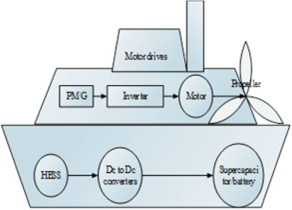
Figure 1: Schematic diagram of electric
3.1 Ship Dynamics and Propeller
The dynamics of the motor and propeller of the ship are mechanically coupled and influence each other, as shown in Fig. 2. The hydrodynamic force of the propeller and the moments are generated from the hull of the ship or the shaft. The ship dynamics are caused due to wave excitation. The error speeds are given to the input of the propeller, and it forms the thrust and torque, and it is fed back to the motor.
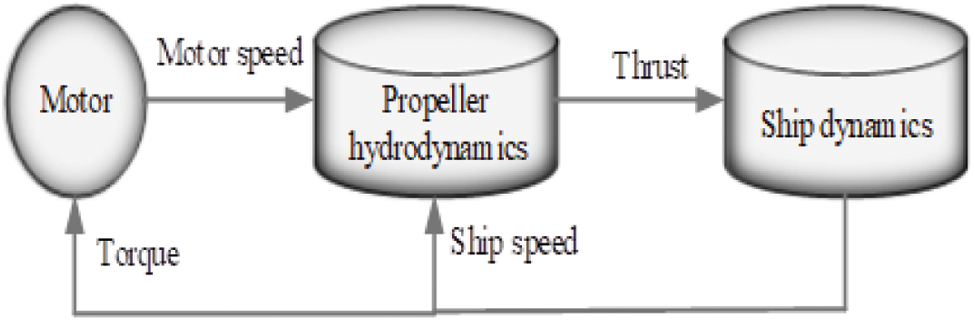
Figure 2: Ship dynamics and propeller model ship propulsion system
3.2 Mathematical Model of Propeller
The propeller is said to be a fan, and it is the ship's forward movement due to the wind speed. A variety of propeller types are available. Below are three blades, four blades, and five propellers depicted in Fig. 3 are considered in this work.
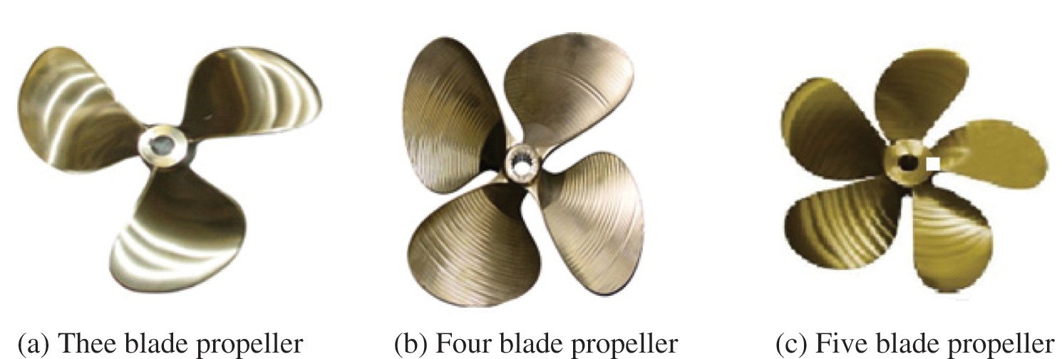
Figure 3: Kinds of propeller. (a) Thee blade propeller (b) Four blade propeller (c) Five blade propeller
The propeller characteristics are torque and thrust. The thrust coefficient (
TH and TO are computed by Eqs. (3) and (4), respectively.
The respective loss factor is added in Eq. (1) as well as in Eq. (2), and the modified equations are given in Eqs. (5) and (6), respectively.
The loss factor lies under some constraints as given in Eq. (7).
The shaft submergence is (
The mechanical power (ppro) is given by Eq. (8).
The propeller speed shall be constant when power and torque change linearly with a large amplitude. If the torque is constant, speed changes occur. The power fluctuation is attenuated by the relevant hybrid energy storage system (HESS) and develop the control strategy to manage the power.
The fluctuation component of the wakefield is represented by Eq. (9).
The angular position of the single blade is noted with (
The strength constraint (sc) is represented by Eq. (10).
The strength constraints are computed by using pitch ratio (
The thrust constraint is represented by Eq. (11).
where Rt is the total ship resistance is to be and
The ship dynamics are associated with some wave excitation, wind, forcing function, etc.
The total resistance of the ship is computed by Eq. (12).
where Rf is the frictional resistance, Rewind is the wind resistance, and Rwm is the wave-making resistance.
The frictional resistance is expressed by Eq. (13).
The wind resistance is expressed by Eq. (14).
The wave-making resistance is expressed by Eq. (15).
3.4 Modelling of Hybrid Energy Storage System (HESS)
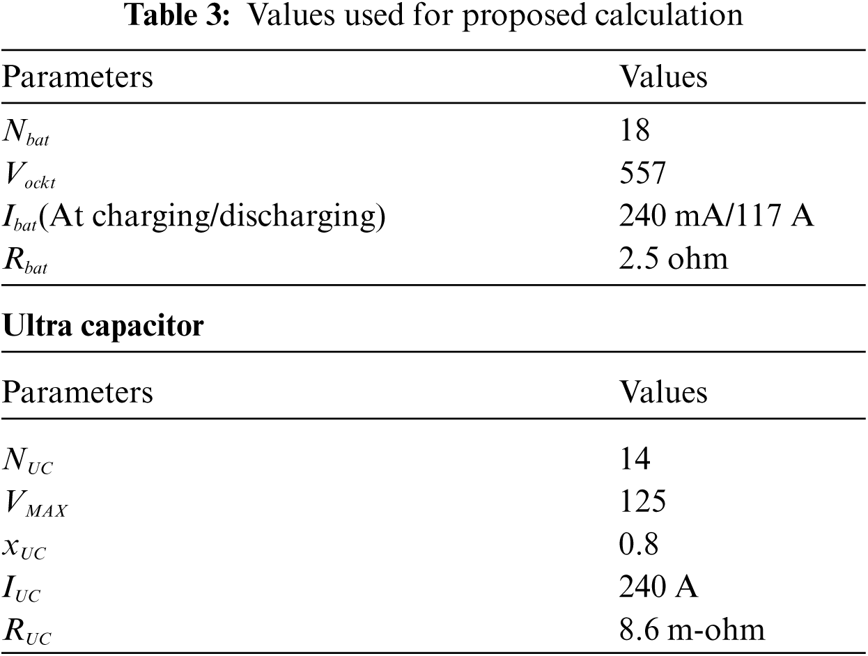
The ZEBRA battery and the Maxwell ultra-capacitor store the power from the generation side for ship propulsion. The benefit of using the ZEBRA battery is high energy density, and the Maxwell ultracapacitor absorbs high current. Thus, HESS is used in this work to absorb high current and high energy density for ship propulsion. Initially, the power of the generation side is stored in the Maxwell ultra-capacitor as it has a long service life and high reliability. Once the power is ultimately stored in the Maxwell ultra-capacitor, then the power is stored in the ZEBRA battery. Both can charge and discharge. Firstly, the battery discharges the HESS power supply.
Battery
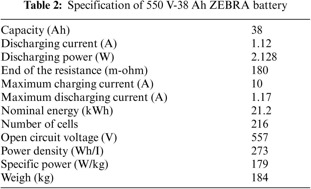
In this work, 550 V-38 Ah ZEBRA batteries are connected across the converters, and the specification of this battery is mentioned in Tab. 2.
State of Charge (SOC)
It is defined as the ratio of current capacity to the maximum capacity of the battery as given by Eq. (16).
Power
The power is expressed by Eq. (17).
where Nbat is battery power states that the number of batteries, Vockt is the open-circuit voltage of the battery, It is the current of the battery, Rabat internal resistance of the battery.
Ultracapacitor
The Maxwell ultra-capacitor with 125 V and 63 F capacitor is considered here, and the related mathematical expression is given by Eq. (18).
The ultra-capacitor is defined with the terms of Number of ultra-capacitor (NUC), Maximum voltage (VMAX), Current (IUC), the state value of ultra-capacitor (xUC), power (PUC), and internal resistance (RUC).
3.5 Model Predictive Control Strategy
The model predictive adaptive control strategy is used here to track the maximum power and reduce the error value presented in the system. Here the load torque is the plant model, and it is given by Eq. (19).
where
Tracking error
The tracking error is said to be the RMS error, and it is computed by Eq. (21).
where j is expressed by Eq. (22).
The above procedures are followed in modeling the dynamic model of the ship with the propeller, thrust, and torque. This can be achieved through mathematical representation. Fuel consumption is reduced by a ship's electrical propulsion system. A predictive controller (MPC) controller is developed to track power and reduce the RMS error rate. The loss factor under the three states is estimated by the Elephant Herding Optimization algorithm (EHO), and the flow chart of the proposed modeling is shown in Fig. 4.
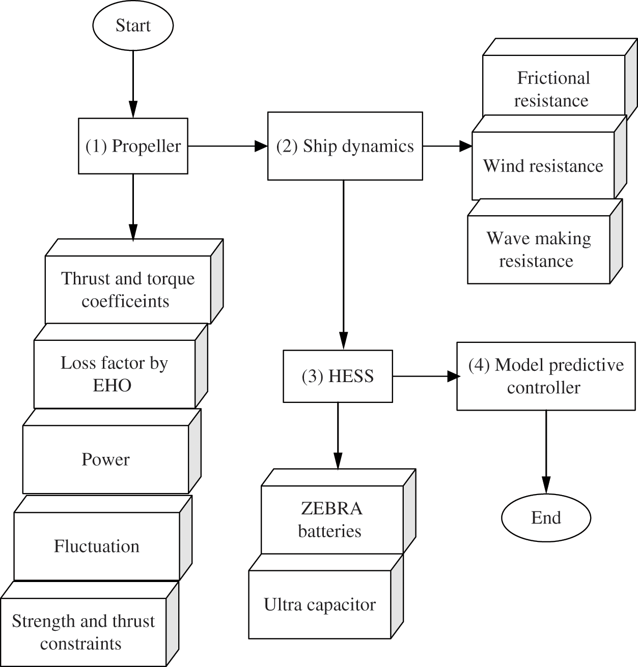
Figure 4: Flowchart of the proposed methodology
A system model is developed and presented herein as a suitable numerical platform to support the analytical work and numerical investigation on the control and optimization of electric ship propulsion systems. This model includes diesel-generator sets and the associated diode rectifier as the primary power source, the hybrid energy storage system (HESS) with batteries, and ultra-capacitors (UC) as the energy storage. A detailed induction motor model and a propeller-ship dynamic model capture the fluctuations in the ship electric drive system induced by the rotating motions of the shaft and the waves and the DC bus dynamic model. Power electronic converters of the energy storage systems and the propulsion motor are used for the power flow control.
4 Elephant Herding Optimization Algorithm [26–29]
One kind of largest animal in the world is to be an elephant. It takes in two recognized species. The primary identification of the animal is a long trunk, which is for grasping, breathing, and lifting water. Several clans are oriented toward the leadership of the matriarch. Under the family, there is one female, calves. The female groups are recognized to live together even though the male elephants will live away from their family.
The EHO algorithm has three idealized functions which are,
(i) The population of the elephant is composed of a kind of clan. The clans contain the fixed integer of elephants.
(ii) At each iteration, the male elephants will be separated from their family and stay solitary away with their groups.
(iii) Eventually, all the clans live together, which is called a matriarch.
This algorithm has the following two operators.
• Separating operator
• Clan operator
Clan updating operator
In each clan, all the elephants live together under the leadership. The clan of each elephant is said to be
The newly updated and the old positions are
The dimension of the clan is expressed by Eq. (25).
Separating operator
The worst fitness is carried out with the separate operator, and it is processed for each iteration, which has been obtained by (26).
Initially, the generation counter is set to 1. The loss factor, radius, and propeller shaft submergence are initialized to the maximum number of iterations. Mention the objective functions as given in Eqs. (3) and (4). For four methods, both the population size and maximum generations are set to fifty. The parameters in EHO are set as the scale factor α = 0.5, β = 0.1, and the number of clans is nClan = 5. In general, all the metaheuristic methods are depended on certain stochastic distributions. Therefore, different runs will generate different results.
The results obtained from the implementation environment for different states of sea level are shown in Figs. 5 and 6 for torque and power, respectively. Fig. 7 shows the wakefield propeller. Fig. 8 shows the load torque of MPC. Fig. 9 shows the convergence of EHO.
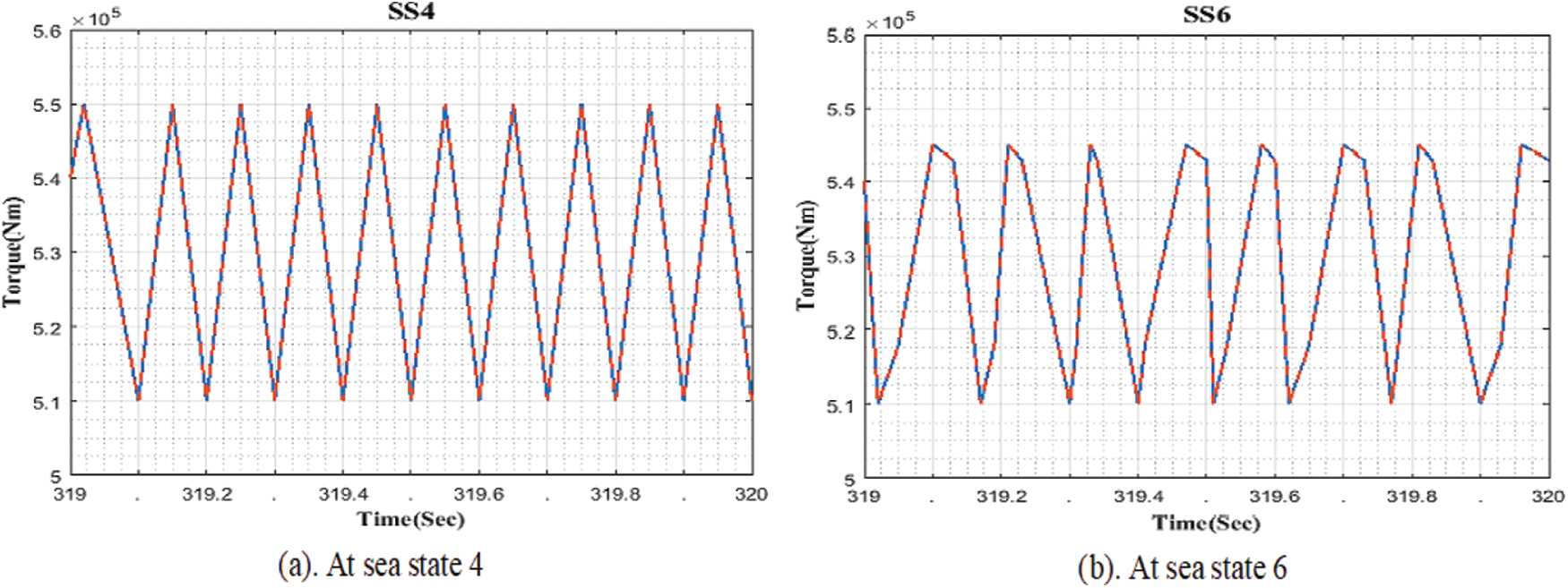
Figure 5: Torque. (a) At sea state 4 (b) At sea state 6

Figure 6: Power. (a) At sea state 4 (b) At sea state 6
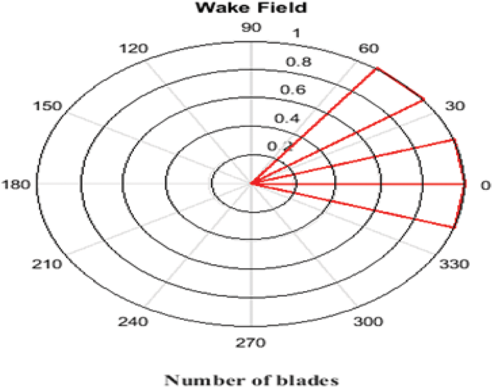
Figure 7: Wakefield of propeller

Figure 8: Load torque of MPC

Figure 9: Convergence of EHO
The energy management problem and control strategy are solved through the proposed approach, and the modeling is done in the working environment of MATLAB R2016a. The electric propulsion system of the dynamic model is presented in the above section to avoid the fuel consumption of the system and the cost reduction.
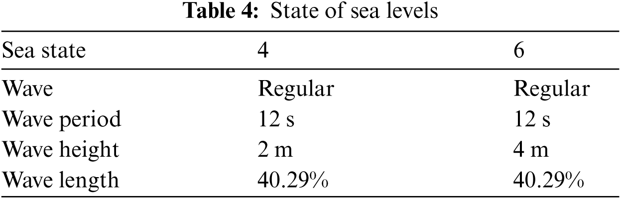
The torque, thrust, and power values are analyzed in the results section through the modeling of the propeller and the ship dynamics. The sea states are represented in Tab. 4, and the torque values of states 4 and 6 are shown in Figs. 5a and 5b, respectively. Both the states have a similar wave period (12 s) and wavelength (40.29%), but the wave height is varied in state 4 (2 m) and that in state 6 (4 m), respectively. The power values for state 4 and state 6 are shown in Figs. 6a and 6b, respectively.
The wakefield of the propeller is shown in Fig. 7, in which three blades are mentioned (3, 4, & 5). The load torque obtained from the predictive model controller is given in Fig. 8. The angular position of the blades is varied, and the limits refer to Eq. (20). Randomly generate the values between the certain intervals have been generated.
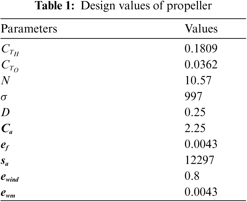
It is quickly converged with up to 3000 iterations. The design values of the propeller used in work are mentioned in Tab. 1, and the specification of the battery is represented in Tab. 2. The corresponding factors used for the design of hybrid energy storage systems are mentioned in Tab. 3. Tab. 4 shows the related data of the state of sea level.
The comparison results of the proposed method with the existing method [22] and the results obtained by BAT [30] and DF [31] algorithms with the same objective functions used by the proposed method have been given in Tab. 5. Tab. 5 shows the RMS error, Maximum error, and loss values, which are reduced than the existing one. The results from [22] have been taken for comparison purposes. The BAT and DF algorithms have been developed to get the results using the same objective function to the effectiveness of the proposed method.
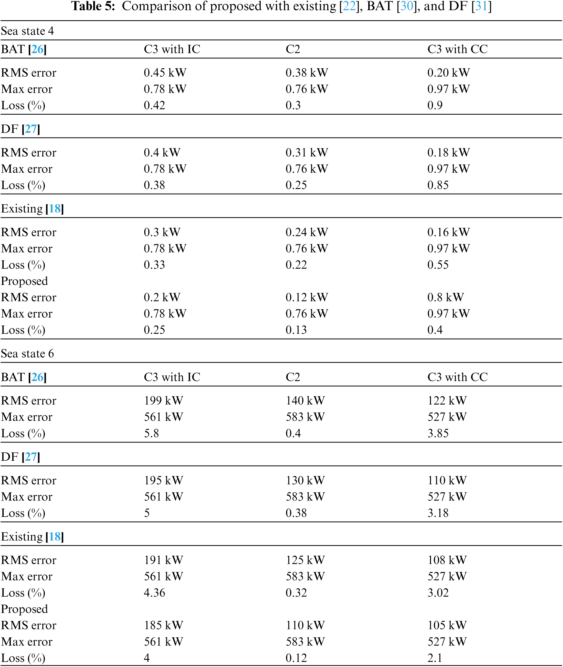
Fig. 10 shows the convergence comparison of the proposed with the existing algorithms like BAT and DF. Those algorithms can yield a higher loss factor. From the comparison, the proposed system achieves better efficiency in terms of loss and error.
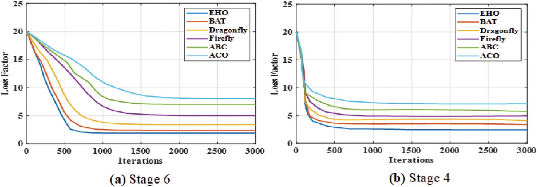
Figure 10: Convergence of various algorithms. (a) Stage 6 (b) Stage 4
An enhanced solution for power fluctuations has been developed in this work with an optimized energy management strategy utilizing EHO. In general, the mechanical ship can use fuel, and in the case of the electric ship, energy storage systems are introduced to make the way hybrid. The ZEBRA battery and MAXWELL capacitor are provided for energy management purposes. The loss factor has been reduced, and the states of the sea have been found through the EHO algorithm. As a result, the effectiveness of the proposed regime has been greatly enhanced. The results are taken out for showing better performance, in which thrust, power, and torque have been computed. The results obtained by the proposed method have been compared with the existing methods. At stages 6 and 4, the loss factor was calculated by varying the iteration from 0 to 3000. The loss factor was calculated by existing and proposed techniques, the existing techniques like BAT, dragonfly, firefly, ABC, ACO. The ACO and ABC existing techniques got higher losses when compared to the proposed EHO. Finally, the performance of RMS error has been minimized, and the loss has been reduced. In the future, the HESS can be developed with an artificial intelligence-based metaheuristic optimization approach.
Acknowledgement: No grant has been received from anywhere.
Funding Statement: The authors received no specific funding for this study.
Conflicts of Interest: The authors declare that they have no conflicts of interest to report regarding the present study.
1. B. Zahedi and L. E. Norum, “Modeling and simulation of all-electric ships with low-voltage DC hybrid power systems,” IEEE Transactions on Power Electronics, vol. 28, no. 10, pp. 4525–4537, 2012. [Google Scholar]
2. C. C. Chan, A. Bouscayrol and K. Chen, “Electric, hybrid, and fuel-cell vehicles: Architectures and modelling,” IEEE Transactions on Vehicular Technology, vol. 59, no. 2, pp. 589–598, 2009. [Google Scholar]
3. Z. Zhou, M. Benbouzid, J. F. Charpentier, F. Schiller and T. Tang, “A review of energy storage technologies for marine current energy systems,” Renewable and Sustainable Energy Reviews, vol. 18, pp. 390–400, 2013. [Google Scholar]
4. S. G. Li, S. M. Sharkh, F. C. Walsh and C. N. Zhang, “Energy and battery management of a plug-in series hybrid electric vehicle using fuzzy logic,” IEEE Transactions on Vehicular Technology, vol. 60, no. 8, pp. 3571–3585, 2011. [Google Scholar]
5. K. Reza, and M. Karimpour, “Development of hybrid propulsion system for energy management and emission reduction in maritime transport system,” Open Journal of Marine Science, vol. 6, no. 4, pp. 482–497, 2016. [Google Scholar]
6. J. Lieh, E. Spahr, A. Behbahani and J. Hoying, “Design of hybrid propulsion systems for unmanned aerial vehicles,” in 47th AIAA/ASME/SAE/ASEE Joint Propulsion Conf. & Exhibit, San Diego, California, pp. 6146, 2011. [Google Scholar]
7. M. Fetcenko, J. Koch and M. Zelinsky, “Nickel-metal hydride and nickel-zinc batteries for hybrid electric vehicles and battery electric vehicles,” in Advances in Battery Technologies for Electric Vehicles, Swanston, UK: Woodhead Publishing, pp. 103–126, 2015. [Google Scholar]
8. S. S. Katoch and M. Eswarmoorthy, “A detailed review on electric vehicles battery thermal management systems,” in IOP Conference Series: Material Science and Engineering, vol. 912, pp. 042005, 2020. [Google Scholar]
9. W. Chen, A. K. Adnanses, J. F. Hansen, J. O. Lindtjorn and T. Tang, “Super-capacitors based hybrid converter in marine electric propulsion system,” in Int. Conf. on Electrical Machines, Rome, Italy, pp. 1–6, 2010. [Google Scholar]
10. Z. Jin, G. Sulligoi, R. Cuzner, L. Meng, J. C. Vasquez et al., “Next-generation shipboard dc power system: Introduction smart grid and dc microgrid technologies into maritime electrical networks,” IEEE Electrification Magazine, vol. 4, no. 2, pp. 45–57, 2016. [Google Scholar]
11. A. D. Pizzo, R. M. Polito, R. Rizzo and P. Tricoli, “Design criteria of on-board propulsion for hybrid electric boats,” in Int. Conf. on Electrical Machines, Rome, Italy, pp. 1–6, 2010. [Google Scholar]
12. J. Hou, J. Sun and H. Hofmann, “Mitigating power fluctuations in electrical ship propulsion using model predictive control with hybrid energy storage system,” in American Control Conf., Portland, OR, USA, pp. 4366–4371, 2014. [Google Scholar]
13. R. D. Geertsma, R. R. Negenborn, K. Visser and J. J. Hopman, “Design and control of hybrid power and propulsion systems for smart ships: A review of developments,” Applied Energy, vol. 194, pp. 30–54, 2017. [Google Scholar]
14. C. R. Lashway, A. T. Elsayed and O. A. Mohammed, “Hybrid energy storage management in ship power systems with multiple pulsed loads,” Electric Power Systems Research, vol. 141, pp. 50–62, 2016. [Google Scholar]
15. B. Jeong, E. Oguz, H. Wang and P. Zhou, “Multi-criteria decision-making for marine propulsion: Hybrid, diesel-electric and diesel mechanical systems from cost-environment-risk perspectives,” Applied Energy, vol. 230, pp. 1065–1081, 2018. [Google Scholar]
16. C. Chen, X. Wang and J. Xiao, “An energy allocation strategy for hybrid ship DC power system based on genetic algorithm,” IETE Journal Research, vol. 62, no. 3, pp. 301–306, 2016. [Google Scholar]
17. M. Spichartz, V. Staudt and A. Steimel, “Modular multilevel converter for propulsion system of electric ships,” in Electric Ship Technologies Symp., Arlington, VA, USA, pp. 237–242, 2013. [Google Scholar]
18. G. Chen, Z. Li, Z. Zhang and S. Li, “An improved ACO algorithm optimized fuzzy PID controller for load frequency control in multi-area interconnected power systems,” IEEE Access, vol. 8, pp. 1–19, 2019. [Google Scholar]
19. M. Zile, “Temperature analysis in power transformer windings using created artificial Bee algorithm and computer program,” IEEE Access, vol. 7, pp. 60513–60521, 2009. [Google Scholar]
20. E. Bottani, P. Centobelli, R. Cerchione, L. D. Gaudio and T. Murino, “Solving machine loading problem of flexible manufacturing systems using a modified discrete firefly algorithm,” International Journal of Industrial Engineering Computations, vol. 8, no. 3, pp. 363–372, 2016. [Google Scholar]
21. J. F. Hansen and F. Wendt, “History and state of the art in commercial electric ship propulsion, integrated power systems and future trends,” Proc. of the IEEE, vol. 103, no. 12, pp. 2229–2242, 2015. [Google Scholar]
22. J. Hou, J. Sun and H. F. Hofmann, “Mitigating power fluctuations in electric ship propulsion with hybrid energy storage system: Design and analysis,” IEEE Journal Oceanic Engineering, vol. 43, no. 1, pp. 93–107, 2017. [Google Scholar]
23. S. M. Mahmoudi, A. Maleki and D. R. Ochbelagh, “Optimization of a hybrid energy system with/without considering back-up system by a new technique based on fuzzy logic controller,” Energy Conversion and Management, vol. 229, pp. 113723, 2021. [Google Scholar]
24. H. Chen, Z. Zhang, C. Guan and H. Gao, “Optimization of sizing and frequency control in battery/supercapacitor hybrid energy storage system for fuel cell ship,” Energy, vol. 197, pp. 117285, 2020. [Google Scholar]
25. X. Gao and L. Fu, “SOC Optimization-based energy management strategy for hybrid energy storage system in vessel integrated power system,” IEEE Access, vol. 8, pp. 54611–54619, 2020. [Google Scholar]
26. G. G. Wang, S. Deb and L. D. Coelho, “Elephant herding optimization,” in 3rd Int. Symp. on Computational and Business Intelligence, Bali, Indonesia, pp. 1–5, 2015. [Google Scholar]
27. E. Tuba and Z. Stanimirovic, “Elephant herding optimization algorithm for support vector machine parameters tuning,” in Int. Conf. of Electronics, Computers and Artificial Intelligence, Targoviste, Romania, pp. 1–4, 2017. [Google Scholar]
28. E. Tuba, A. Alihodzic and M. Tuba, “Multilevel image thresholding using elephant herding optimization algorithm,” in Int. Conf. on Engineering of Modern Electric Systems, Oradea, Romania, pp. 240–243, 2017. [Google Scholar]
29. G. G. Wang, S. Deb, X. Z. Gao and L. D. S. Coelho, “A new metaheuristic optimization algorithm motivated by elephant herding behaviour,” International Journal of Bio-Inspired Computation, vol. 8, no. 6, pp. 394–409, 2016. [Google Scholar]
30. X. S. Yang, “Bat algorithm for multi-objective optimization,” International Journal of Bio-Inspired Computation, vol. 3, no. 5, pp. 267–274, 2011. [Google Scholar]
31. S. Mirjalili, “Dragonfly algorithm: A new meta-heuristic optimization technique for solving single-objective, discrete, and multi-objective problems,” Neural Computing & Applications, vol. 27, no. 4, pp. 1053–1073, 2016. [Google Scholar]
 | This work is licensed under a Creative Commons Attribution 4.0 International License, which permits unrestricted use, distribution, and reproduction in any medium, provided the original work is properly cited. |