DOI:10.32604/cmc.2022.021349
| Computers, Materials & Continua DOI:10.32604/cmc.2022.021349 | |
| Article |
New Hybrid IoT LoRaWAN/IRC Sensors: SMART Water Metering System
1Mendel University in Brno, Faculty of Agrisciences, Department of Agricultural, Food and Environmental Engineering, 613 00, Brno, Czechia
2Slovak University of Agriculture in Nitra, Faculty of Engineering, Department of Machines and Production Biosystems, 94976, Nitra, Slovakia
3VSB–Technical University of Ostrava, Faculty of Electrical Engineering and Computer Science, Department of Cybernetics and Biomedical Engineering, 708 00, Ostrava-Poruba, Czechia
*Corresponding Author: Petr Koudelka. Email: petr.koudelka@mendelu.cz
Received: 30 June 2021; Accepted: 18 August 2021
Abstract: The massive development of internet of things (IoT) technologies is gaining momentum across all areas of their possible deployment—spanning from Industry 4.0 to eHealth, smart city, agriculture or waste management. This ongoing development is further pushed forward by the gradual deployment of 5G networks. With 5G capable smart devices, it will be possible to transfer more data with shorter latency thereby resulting in exciting new use cases such as Massive IoT. Massive-IoT (low-power wide area network-LPWAN) enables improved network coverage, long device operational lifetime and a high density of connections. Despite all the advantages of massive-IoT technology, there are certain cases where the original concept cannot be used. Among them are dangerous explosive environments or issues caused by subsurface deployment (operation during winter months or dense greenery). This article presents the concept of a hybrid solution of IoT LoRaWAN (long range wide area network)/IRC-VLC (infrared communication, visible light communication) technology, which combines advantages of both technologies according to the deployment scenario.
Keywords: IRC/VLC; LoRaWAN; LPWAN; massive IoT; smart metering
The team at VSB–Technical University of Ostrava has been conducting research in the field of visible light communication (VLC) for approximately ten years. The original system was based on the IEEE 802.15.7 standard: Short-Range Optical Wireless Communications. This standardization is closely related to networks based on the Ethernet frames and often employs relatively simple digital modulation such as on-off keying (OOK) or variable pulse position modulation (VPPM). The latest research trend is the combination of adaptive mapping through multistate quadrature amplitude modulation (M-QAM) with various orthogonal frequency division multiplexing (OFDM) implementations. OFDM is the common denominator of several modern digital radio frequency technologies (WiFi, GiFi, LTE, LTE-A, 5G) or broadband over powerlines (BPL) solutions, including modern communication systems that employ coaxial cables (DOCCIS 3.1). In other words, if there is a problem with signal interference or occurrence of inter-symbol interference due to multipath propagation, the OFDM is often employed as a solution. This trend was also reflected in the standardization of VLC communication, as the IEEE 802.15.7a work group is currently dealing with the issue of combining higher speed (
Internet of things (IoT) LoRaWAN technology was used in the concept, while for the final deployment a massive-IoT technology solution is expected [1,2]. Therefore, the development of the concept was built on the basis of a highly modular platform that will allow the future deployment of massive-IoT without any unnecessary modifications. The resulting concept platform was deployed in the real world scenario—it was used for smart reading of water consumption on the backbone network of a water company. As the final hybrid solution was supplemented by other smart functions (among them temperature and humidity sensing, backbone collector flood warning or emergency flow identification, which reports damaged piping), the concept was expanded with fog computing mechanisms based on the principles of Petri nets. The concept is fully prepared for future deployment of energy harvesting solutions, which are especially promising for systems with subsurface applications (water turbine generator, Peltier device).
The first chapter briefly summarizes the current state of the art of both basic technologies used in the presented hybrid concept—the IoT technology based on LoRaWAN (with future deployment of NB-IoT, which is part of 5G) and wireless data transmissions in the visible and IR spectrum. The concept of the hybrid SMART Water Metering System is then presented in the third chapter, which describes not only the block diagram of the concept itself, but also summarizes the results of measurements of individual technologies and even the joint hybrid solution. Since the wireless monitoring must meet the legal criteria given by both national and European law, the key requirements for the technical side of the concept are presented in Chapter 4. Chapter 5 is focusing on the data gathered in real measurements, where the data is transferred from the sensory part (consumption reading) to the central part via the VLC/IR spectrum and then gathered by a centralized LoRaWAN gateway. The presented results show the coverage of the monitored area of the municipality of Žd'árná during different seasons, while also discussing the influence of various phenomena on the experiment itself.
The increasing support of the smart city concept is leading to ongoing development and deployment of smart energy reading technologies [3,4]. Multiple different approaches are proposed in the field of remote reading of water meters. The pulse output of the water meter is the most commonly used solution [5,6]. There are also certain approaches that leverage the image recognition technology, but they often require more energy [7,8]. Li and Chong in 2019 [9] designed and implemented a self-powered smart water meter, which used a dedicated water turbine generator that recharged the battery that was driving the entire device. This approach significantly extended the service life of the device. There are even other solutions that can be used to recharge the onboard battery [10–12].
The most widely used technologies for long-distance data transmission in the smart city concept include low-power wide area network (LPWAN) technologies, such as long range wide area network (LoRaWAN), SigFox, narrowband IoT (NB-IoT) and their combinations [13–16]. Mekki et al. in 2019 [17] described individual technologies and compared them in terms of usability in the field of IoT. A comparison of individual factors can be seen in Fig. 1a.
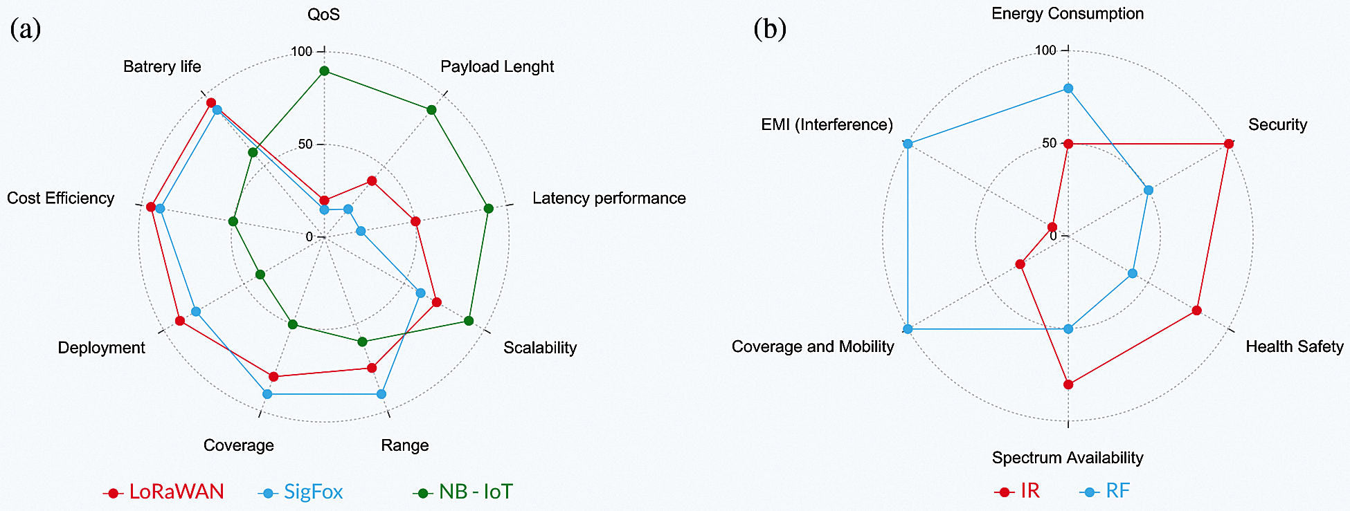
Figure 1: (a) Comparison of individual factors in terms of usability in the IoT field [17]. (b) Comparison of RF and VLC in terms of selected parameters [18]
As described by some authors, the deployment of these technologies can be in some specific cases very problematic [19,20]. In the case of LPWAN technologies, the problem lies in deployment of active solutions in so-called deep indoor environments. Among them are water supply shafts or basements of houses [21,22].
A combination of individual technologies can be used as a solution to these problems. Delgado-Rajo et al. in 2020 [23] described a monitoring device based on a hybrid RF/VLC technology, where VLC (or Zigbee) technology is used to transfer data from the accelerometer, while the LoRaWAN is used to transfer the data further to local gateway. This approach has numerous advantages, including lower energy consumption, wider usable spectrum, higher security and low susceptibility to interference. However, it also has several disadvantages. Among them are the low range and limited mobility of the end point [18–24]. The comparison of radio frequency (RF) and VLC technology based on selected parameters can be seen in Fig. 1b.
Due to the extensive experience and the mentioned requirements for high degree of modularity, a platform from National Instruments was chosen for the prototyping and construction of the alpha model [25]. The combination of virtual instrumentation (LabVIEW) and a software-defined radio (SDR) hardware platform offers a number of benefits. Mainly the speed of compiling and adjustments of the source code is crucial. Any changes can be tested straight away and the results can be observed immediately. The SDR is also independent on the connected modules. The team can freely change amplifiers or transmitting (luminaires) as well as receiving (photodetector) elements. The NI SDR itself (universal software radio peripheral-USRP) can also be modified to some extent. In each SDR there is either one two slot or a pair of one slot RF cards. These cards determine in which band the SDR will operate. Due to the characteristics of VLC communication, it is necessary to use a set of Ettus LFRX/LFTX daughterboards that operate from DC to 30 Mhz.
The second version of our prototyping platform represented a substantial leap from QAM to OFDM with QAM mapping [26]. The whole system retained the HW elements from the QAM system and was controlled by software written in LabVIEW 2018 32-bit. The transmitted symbol had to be continuously amplified—an amplifier operating from 1 to 200 MHz was introduced. The luminaire itself (white LED/IR LED) was modulated by a commercial ZX85-12G+ Bias-T. The team used a commercial Thorlabs PDA36A-EC PIN photodetector as a receiving element. While this system represented a generational leap, it had its own problems. A significant limitation was the implementation itself, since the LabVIEW was a 32-bit environment. The backbone software was therefore limited by usable RAM and the evaluation part suffered significant instability and crashed periodically. The system has reached an effective communication distance of up to eight meters.
The third, and so far the latest, version of our platform was designed to solve the previously encountered problems. The entire software was completely reprogrammed and ported to the modern 64-bit LabVIEW NXG [26]. Instead of the old USRP 2921, the system now runs exclusively on one modern USRP 2954R, which is connected to the computer via a proprietary PCIe link. The control PC has also been updated and runs on the much more powerful Core i9 Extreme platform. Thanks to all these changes, the communication distance has risen from eight meters to fifty, which is a significant improvement. At the same time, it is not necessary to solve the synchronization—the transmitter and receiver are precisely synchronized via the SDR bus. The system was designed with future deployment in service shafts in mind. The basic scheme of the hybrid system can be seen in Fig. 2.
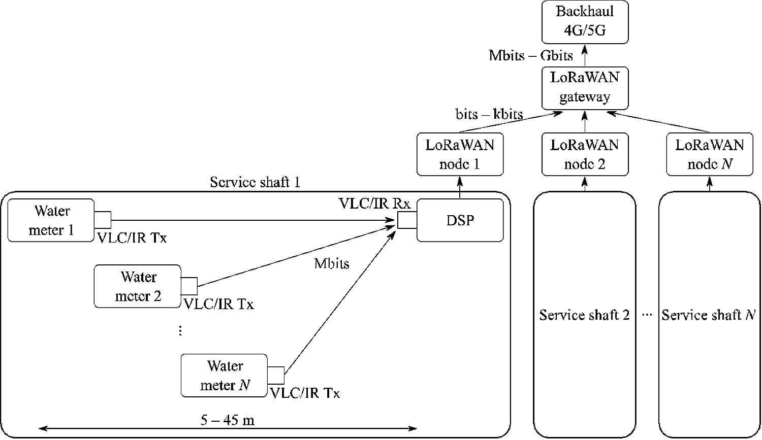
Figure 2: Hybrid system-LoRaWAN + IR/OFDM for M-QAM subcarrier for deployment in service shafts
The third version was first tested in an environment similar to future deployment scenarios. The receiver had a fixed position at the one end of the dark corridor, while the receiver was moved at prespecified steps. Based on the preliminary results, the system is capable of communicating up to 46.2 m at 4-QAM mapping. This configuration used narrower channels (1 MHz bandwidth) with lower carrier frequencies (1.5 MHz carrier). The “high-speed” mode (128-QAM mapping) is only capable of communicating up to 11.7 m, which is still more than enough for underground water shafts. The system development is slowly steering towards cognitive radio, so the platform should be capable of adjusting the parameters (bandwidth, M-QAM mapping) dynamically according to measured parameters. The constellations with effective limits for individual M-QAM mapping configurations can be seen in Fig. 3.
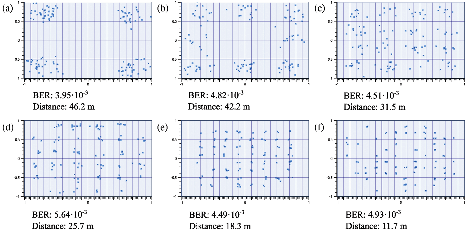
Figure 3: The maximal reachable distance at different M-QAM mapping configurations, according to the BER limits. (a) 4-QAM; (b) 8-QAM; (c) 16-QAM; (d) 32-QAM; (e) 64-QAM; (f) 128-QAM
The latest version of OFDM system was designed to employ 256 subcarriers, but due to the requirements for certain degree of robustness, only the central 150 were used. Over the course of measurements, the spectra of the received symbols degraded significantly. Fig. 4 shows the spectrum of OFDM symbols measured at different distances. While the symbols were influenced significantly, the system maintained communication up to the limiting values mentioned earlier.
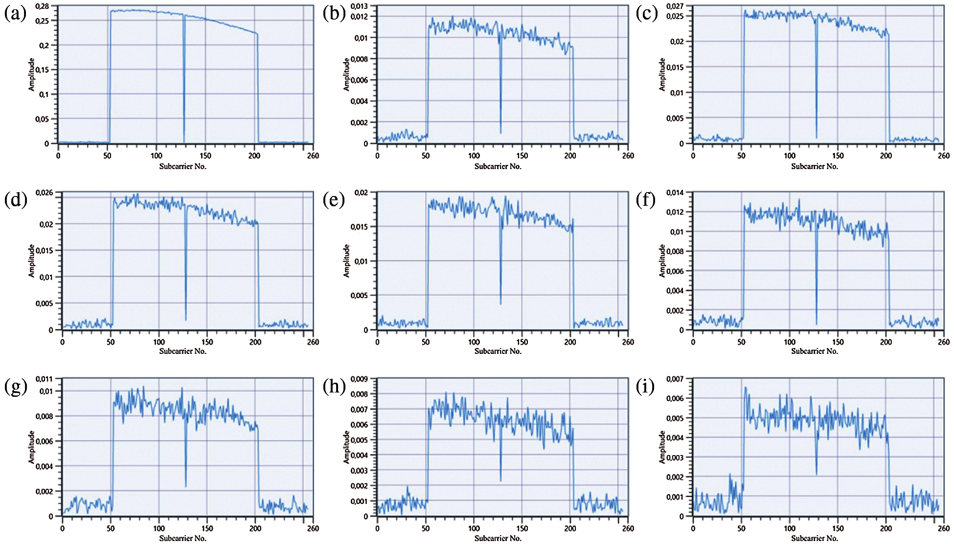
Figure 4: The degradation of OFDM symbols at different distances. (a) 5 m; (b) 10 m; (c) 15 m; (d) 20 m; (e) 25 m; (f) 30 m; (g) 35 m; (h) 40 m; (i) 45 m
Before the final deployment, it is crucial to determine the appropriate ratio of range and uplink/downlink rate. Although the system is able to operate on the mentioned 50 meters, the transmission speeds are severely limited. As the distance between the receiver and the transmitter increases, the effective transmission speed of the platform decreases. The channel quality requirements can vary according to the target deployment of the entire system. In case of smart homes, it is much more likely that the communication will be carried out on shorter distances at higher speeds, while in case of communication between vehicles, the distance changes dynamically, which also leads to dynamic changes in the transmission channel. Another, still very important scenario, includes reading data from static points. In this scenario, the different consumption meters (electricity meters, gas meters, water meters) are located at fixed coordinates. The maximal effective communication distance of the whole system is much more important, since the meters are often in limited spaces and the service shafts are not very spacious. If each individual meter contained an LED matrix that starts to light up/transmit automatically when the service shaft is opened, it would be possible to insert only the receiver and read the current consumption. Therefore, the service technician would not have to enter confined spaces at all.
The system was therefore tested in longer service shafts to verify the earlier measurements. The tests were very brief, but the results correspond to the earlier measurements described by Figs. 4–6 shows the preliminary results from measurements carried out in shafts. A directional light source was used to focus the light beam into the shaft. Therefore it was possible to reach up to 50 m of illuminated area. However the system at its most robust configuration only managed to maintain reliable connection to up to approx. 47 meters. Further testing is necessary to verify the whole system under different conditions and to analyze other important parameters (error vector magnitude-EVM, modulation error ratio-MER etc.).
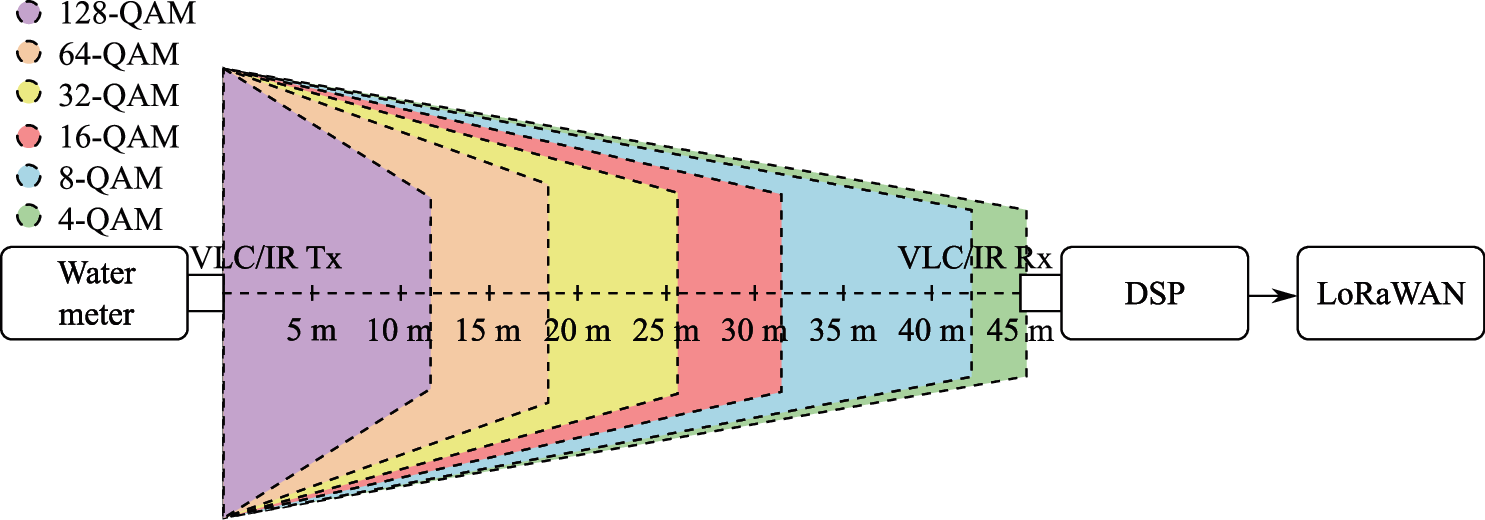
Figure 5: Preliminary results of testing in service shafts. The effective communication distance of different M-QAM mapping configurations. Forward error correction (FEC) limit bit-error ratio (BER) = 3.8⋅10−3
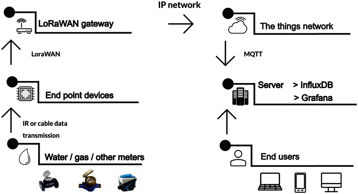
Figure 6: Basic (or default) forms of the presented modular system
4 Legal Conditions in Czech Republic/EU
The Directive 2018/2002 of the European Parliament and of the Council, which amends the Directive 2012/27/EU on energy efficiency, was issued for the area of metering and subsequent billing of heat and water in apartment buildings. This Directive states that energy efficiency should be considered as a key element and a priority when considering a future investments in the Union's energy infrastructure. Among other things, the paragraph 22 states the following: The effective management of water can make a significant contribution to energy savings. The water and wastewater sectors account for 3.5% of electricity use in the Union and that share is expected to rise. At the same time, water leaks account for 24% of total water consumed in the Union. The energy sector is the largest consumer of water, accounting for 44% of consumption. Therefore the potential for energy savings through the use of smart technologies and processes should be fully explored.
With regard to the requirements of this directive, and thus the subsequent introduction of the obligation of initially quarterly, later from the beginning of 2022 monthly billing of services, it will be possible to install heat meters, heating costs indicators and hot water meters only with remote reading capabilities. Furthermore starting from 25.10.2022, only the remotely readable devices can be installed and any devices installed before this date must be retrofitted with a remote reading device or replaced completely by 1.1.2027.
Specific requirements for water meters are set out in Government Regulation No 120/2016 Coll. on the assessment of the conformity of measuring instruments when the products are released to the market. Annex no. 3 states that the quality requirements of the measuring device must be taken into account when designing the concept of a smart water metering system. In case of the water flow range, the defined conditions are following:
Furthermore, the water temperature range is also specified and it must meet the following conditions:
● from 0.1°C to at least 30°C, or
● from 30°C to at least 90°C.
The water meter can be designed to operate in both ranges. The range of relative water pressure at Q3 is from 0.3 bar to at least 10 bar.
The maximum permissible error (MPE), whether positive or negative, is in case of water flows at a flow rate ranging from a transient flow rate (Q2) (including) to an overload flow rate (Q4) 2% for water with temperature ≤30°C and 3% for water with a temperature >30°C. In case of MPE for flow rates at flows ranging from minimum flow (Q1) to transient flow (Q2) (excluding), the value is 5% for water of any temperature. There must be no abuse of the MPE or systematic favoritism of one of the parties, whether it is supplier customer.
Stability test—after the appropriate tests have been carried out (including parameters given by the manufacturers), the following criteria must be met:
The variation of measurement result after the stability test was carried out with respect to the initial measurements must not be greater than:
a) 3% of the volume measured in the range from Q1 included to Q2 excluded,
b) 1.5% of the volume measured in the range from Q2 included to Q4 included.
The error in indicating the volume measured after completion of the stability test must not be greater than:
a) ±6% of the volume measured in the range from Q1 included to Q2 excluded,
b) ±2.5% of the volume measured in the range from Q2 included to Q4 included for water meters that are designed to measure water with a temperature range from 0.1°C to 30°C,
c) ±3.5% of the volume measured in the range from Q2 included to Q4 included for water meters that are designed to measure water with a temperature range from 30°C to 90°C.
Every mentioned legislative aspect had to be taken into account when designing the concept. The resulting solution was tested and it met the required aspects.
The earlier version of the smart water metering system was already presented by the authors in their previous publication [6]. The earlier version was using a MicroBUS to transfer data between water meters and individual endpoints or other peripherals. Fig. 6 shows the basic scheme of the tested highly modular system.
The firmware of the integrated STM32 microcontroller on the designed IoT platform uses the Ivory and Ivory-Tower ecosystem, which was created by Galois. It is written in the functional programming language Haskell [27,28]. The main advantage of this solution is its high degree of adaptability—it is possible to quickly change functionality based on current requirements. The main concept of this framework (called The Tower) is to describe the behavior of monitors (so-called Hoare) with synchronously specified channels that resemble a Petri net. This description of behavior is then transformed into C language, along with the helper code.
The smart water metering system is designed for continuous data collection (pulse counter, humidity, temperature and other peripheral sensors). As shown in Fig. 5, the data is then sent in a specified time interval (15–60 min.) by a LoRaWAN gateway directly to the server, where they can be inspected by authorized users. During the testing phase, the device itself was powered by a wall outlet adapter. When the device is used in areas without dedicated power (i.e., in water supply shafts), it is powered by batteries (3x AA LR6 battery). The device can be operated in power efficient mode (sending data every 1 h)—the battery life is preliminary calculated to last at least 2 years (according to the STM32CubeMX). The frequency of LoRaWAN data transmissions (which are the most energy demanding process) can heavily influence the battery life of the deployed device. To prolong the lifespan of batteries, the system is also capable of automatic charging either via direct power supply or by a connected water turbine generator F50–5 V (200 mA). The batteries are then used as an auxiliary power source.
As was mentioned in the introduction, a LoRaWAN technology was used during the experiments, since the 5G is in Czech Republic still not yet fully deployed. However, the modularity of the system offers seamless transition to future NB-IoT solutions. The LoRa modulation is based on Chirp-Spread-Spectrum, which retains the same low power properties as FSK modulation, while also significantly increasing the effective communication range. Chirp-Spread-Spectrum is used mainly in military and space communications due to the longer reachable communication distances. It is also very resistant to interference. LoRa is the first low-cost implementation of this technology for commercial deployment [29].
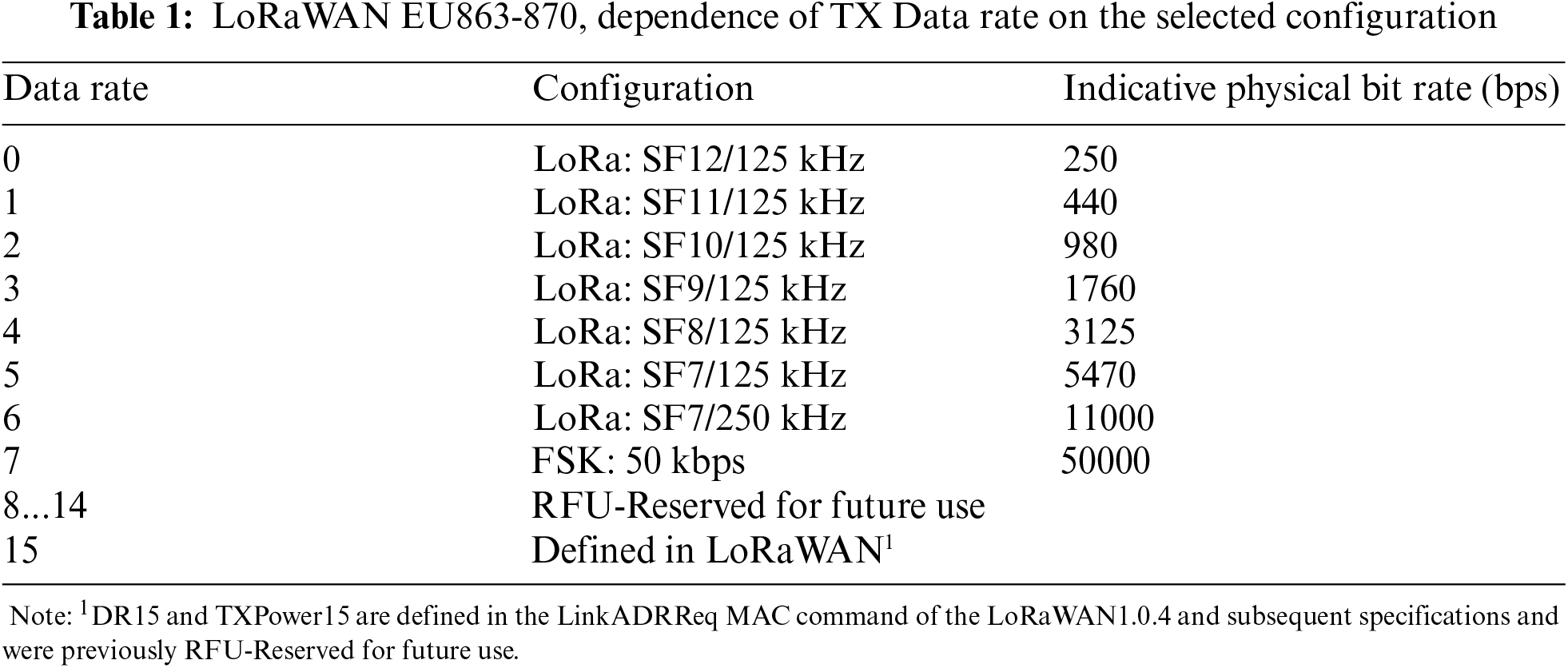
Another advantage of LoRa lies in its flexible configuration, which allows the operator to change the signal range. Multiple parameters can be adjusted, among them are bandwidth (BW), spreading factor (SF) or coding rate (CR). According to the EU863-870 specification for industrial, scientific and medical (ISM) band, the usable bandwidth can be either 125, 250 or 500 kHz. The SF can be configured in the range of 7–12. The lower the spreading factor is, the shorter the effective communication distance. CR improves reception robustness by encoding 4-bit data with error-correction redundancies in 4/5, 4/6, 4/7 or 4/8 variants. As can be seen in Tab. 1, the error correction is introduced for CR 4/7 and higher configurations. CR 4/8 variant does not improve the error correction capabilities, but it can be used to detect errors much easier. CR 4/5 therefore does not have any significant advantage over other solutions and CR 4/6 only increases the number of detected bits with errors, without correcting them. Therefore, if the error detection and correction are necessary, at least CR 4/7 coding must be used. However there is a significant disadvantage to higher coding rate configurations—CR 4/7 increases the size of the data content by 75% in comparison to system that does not use encoding at all [30].
The bit rate of LoRa can be calculated by the following formula [30]:
where the SF is the spreading factor, BW is bandwidth and CR is coding rate.
As indicated by Eq. (4), the SF is one of the dominant factors for calculating the bit rate, which then defines the physical data rate (referred to as DR—data rate), which can be also seen in Tab. 1. This table does not include DR in the 8–14 range, since it is not implemented in ISM EU863-870.
6 Practical Deployment of Hybrid IoT LoRaWAN/IRC Sensors
To verify the year-round functionality of the system in the selected locality, two complex measurements were carried out. The first measurement took place in May 2020. This specific period was chosen due to the growth of a massive amount of vegetation, which may have a negative impact on the propagation of the signal in the locality. This experiment included over 450 measurements, with results visible in Fig. 7a. One of the goals was to measure not only the currently urbanized areas but also the places that were approved for future development.
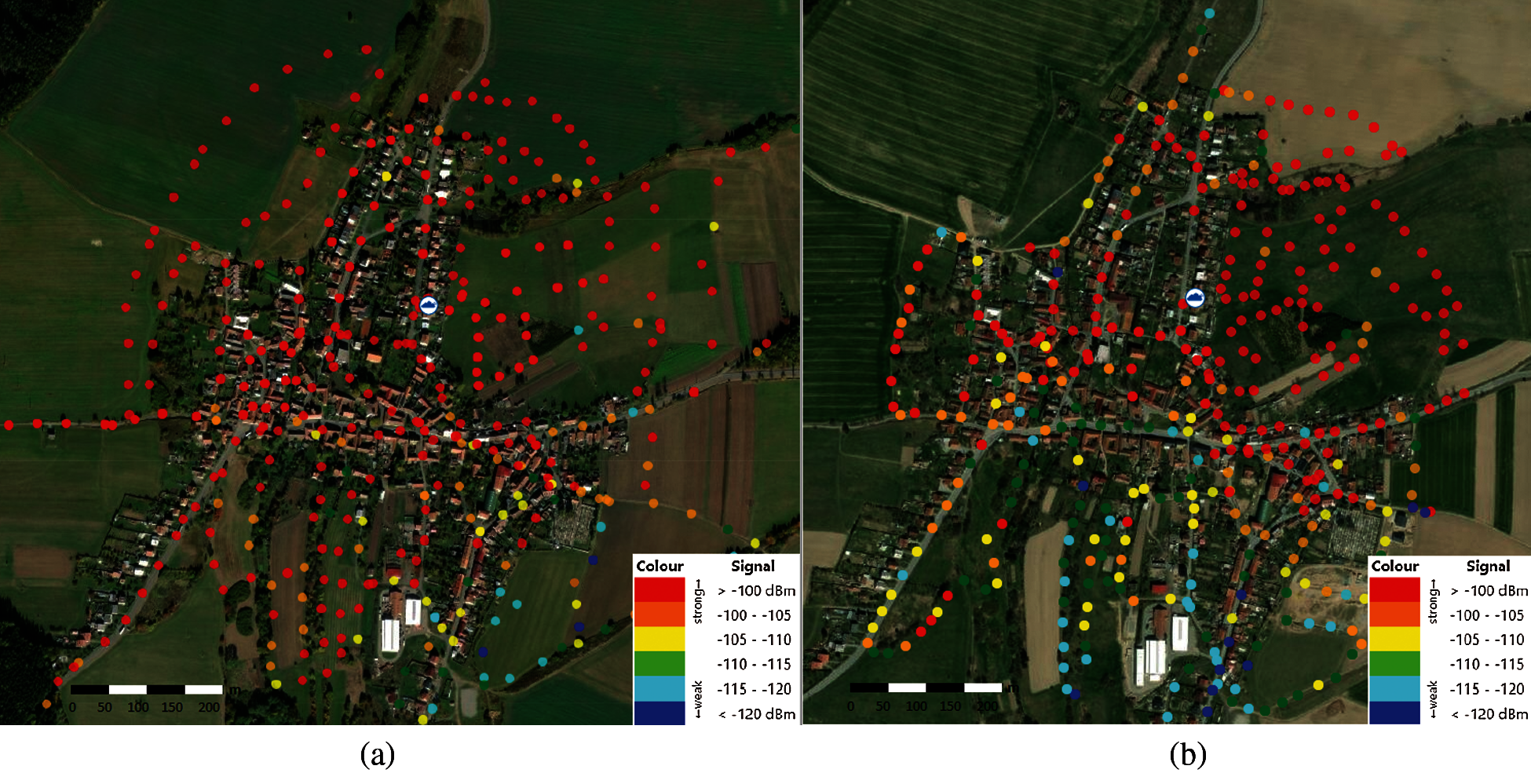
Figure 7: (a) Measurements in May 2020, (b) Measurements in January 2021-map scale 1:6000
The second measurement was carried out in the winter of 2020. This period is also specific, since the whole village (including service shafts) is covered by approx. 10–15 cm of snow. In total, over 500 control measurements were performed. The measurement results are shown in Fig. 7b.
The location of LoRaWAN is in Fig. 7 symbolized by the Cloud symbol. Based on the gathered data a preliminary report on the received signal strength (in dBm) was created.
The gathered data were then used to create HEAT MAPS, which compare the signal strength in the selected locality under different meteorological conditions (Fig. 8).
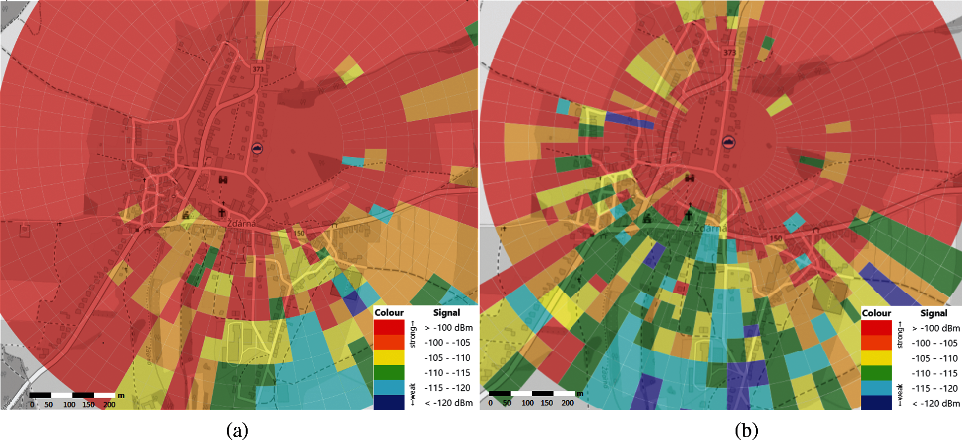
Figure 8: (a) HEAT MAP from May 2020 (b) HEAT MAP from January 2021-map scale 1:6000
Based on Fig. 8a, it can be noticed that the problem with signal propagation is mainly in the southern and southeastern directions. This is caused mainly by a relatively dense development in this area and a significant elevation of village profile. However, the signal strength in this area is still sufficient for data transmission, as it ranged from 110 to 120 dBm. The packet loss was also avoided.
The situation in Fig. 8b is different. It is quite obvious that there was a fairly significant deterioration in the signal transmission parameters. This is again most evident in the southern and southeastern part. It is important to mention that all measurements were carried out on the surface. Placing the end device in the water supply shafts could lead to significant signal attenuation. It is therefore advisable to place the transmitting part of the proposed device to the surface as closely as possible. It is also important to mention that even during winter months, there was no complete loss of signal at any monitored points in the village. The device was therefore able to communicate even under such borderline conditions. Signal coverage in blind spots (inaccessible—i.e., due to private ownership) was calculated by interpolation.
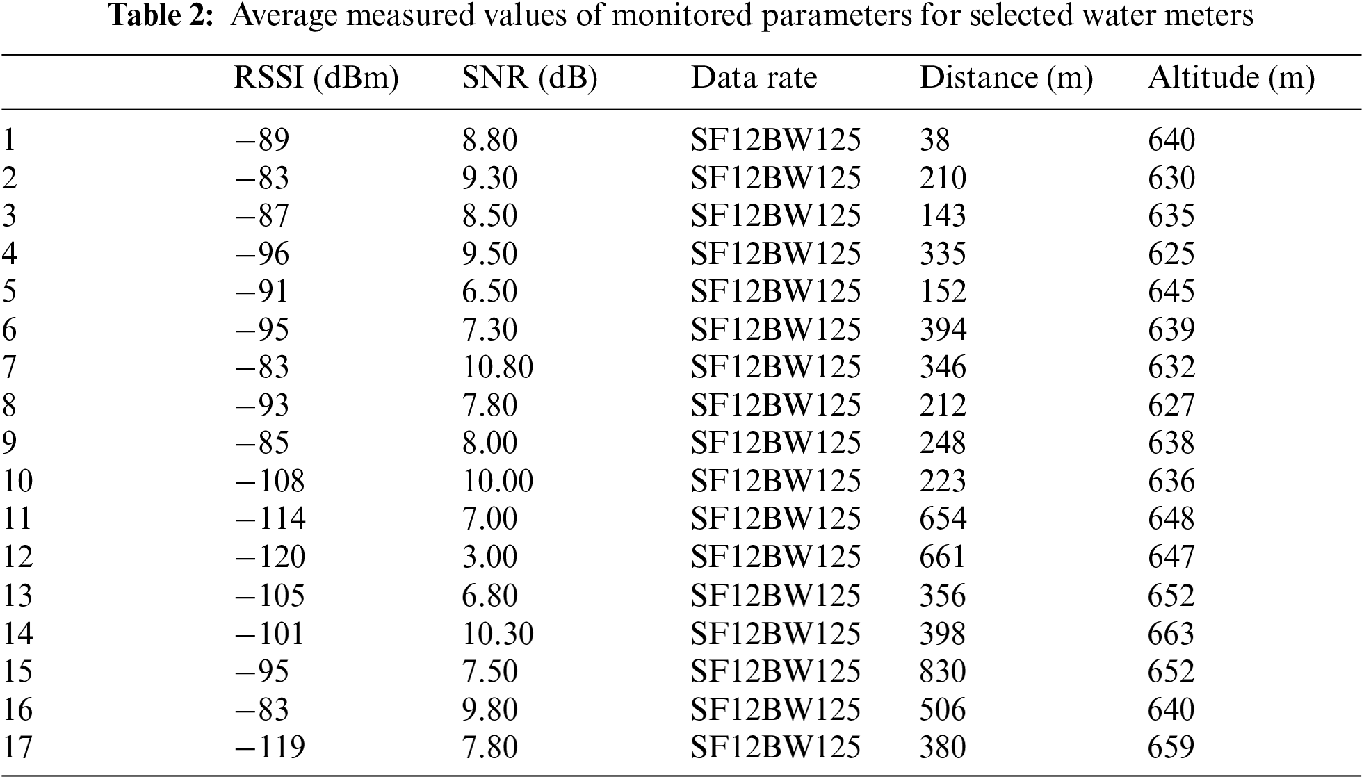
In the last phase, the Hybrid IoT LoRaWAN/IRC Sensors were experimentally deployed in subsurface applications. In this scenario, 9 cellars of selected family houses (red numbers on Fig. 9) and 8 water meter shafts (green numbers on Fig. 9) containing main supply control valves were used. The functionality of the entire system was monitored, along with the received signal strengths and current values of monitored water meters—presented in Tab. 2. According to the measured values in Tab. 2, all devices in the village were able to reliably communicate or receive and transmit data. Fig. 9 shows the specific locations where the Hybrid IoT LoRaWAN/IRC Sensors were deployed, while Fig. 10 shows photographs taken during measurements in both field conditions and laboratory conditions.
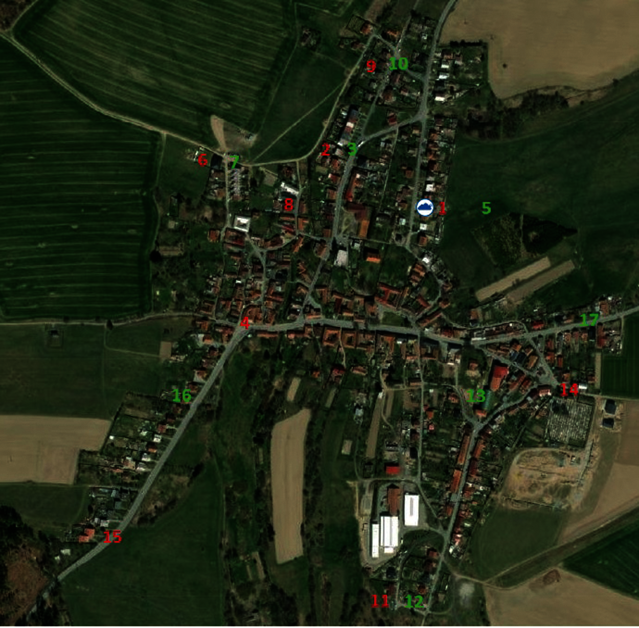
Figure 9: Locations where the Hybrid IoT LoRaWAN/IRC Sensors were deployed—map scale 1:6000
As can be seen in Fig. 10, the deployment in real conditions is not possible without adequate protection of the device itself against the water or dust. The earlier covers were printed by a 3D printer. This approach initially proved inefficient, since the material rapidly degraded under stressful conditions. This was mainly caused by an unsuitable type of filament. Most problems with degradation were solved by a new type of PET filament. The newest cover is build around standardized wiring boxes with guaranteed IP54 rating.
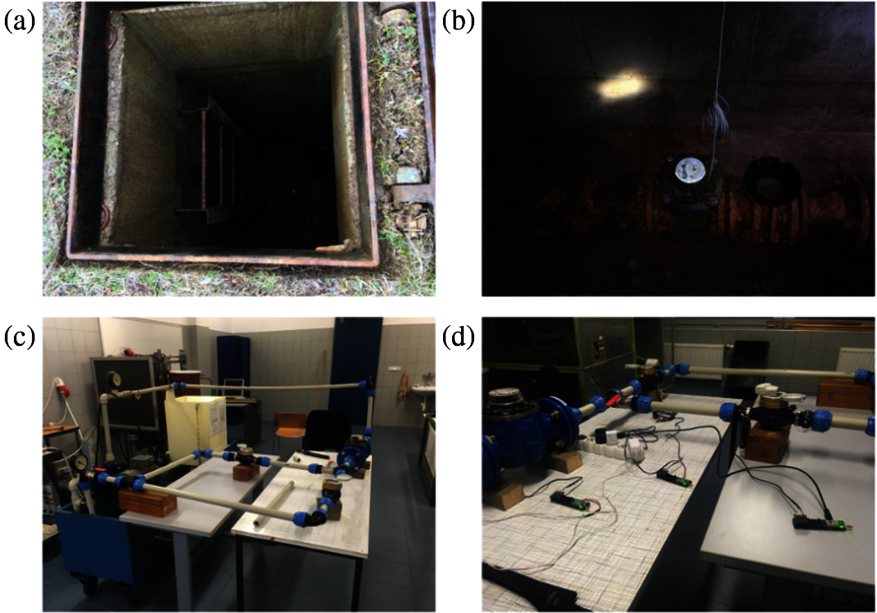
Figure 10: Photographs taken during measurements. (a) watter supply shaft, (b) shaft entrance, (c) laboratory circuit, and (d) connected peripheral devices
Due to the ever-increasing support of the smart city concept and the ongoing emphasis on monitoring of energy consumption, the number of available solutions and technologies is currently on the rise. However, as some authors clearly showed, these technologies have different limitations that must be considered before their deployment [22,31–34]. Some solutions cannot be deployed in their own subnets, which can be undesirable, mainly due to partially compromised security. For this reason, various hybrid solutions are currently being developed. These solutions combine different technical advantages of different technologies to create an optimal ecosystem for different environments. An example was presented by Delgado-Rajo et al. [23]. Their hybrid solution combines ZigBee and VLC technology for continuous data collection, while the LoRaWAN is used to gather this data to a centralized node. Similar solutions that combine multiple data transfer technologies were presented by other authors [18,35,36]. These hybrid solutions are especially tailored for deployment in areas with higher security (direct LoS–VLC) or dangerous environment (risk of explosion).
The VLC/IR combination is currently explored by multiple teams. While the technology can operate in standalone mode it is more suitable for hybrid deployment. Direct Line of Sight operation can be both advantageous and disadvantageous. While it offers a certain degree of security, the communication is limited by the illuminated area. VLC/IR should be only deployed in areas, where the receiving element is either moving constantly in illuminated areas (vehicle-to-vehicle communication etc.) or has a fixed position (service shafts). The deployment in fixed scenarios is also much cheaper, since the system does not require a specialized receiver (image sensor) that would track the position of a moving transmitter (or light source).
These technologies can be only deployed in areas with built-in infrastructure that are covered by relevant technologies. This can be very limiting in certain situations (communication at sea, remote areas, developing countries). The solution can be the deployment of LPWAN technology, which will offer a worldwide coverage by satellites [37,38]. LPWAN also has its limits, among them is a larger time-delay for data transmissions (up to seconds). The monitored area also has to be covered by an appropriate satellite that can be used for data transmissions [39]. For example, Kineis presented their own solution of satellite LPWAN technology, which currently allows limited data transmissions every 2 h. They plan to launch additional 25 nanosatellites, that will shorten the transmission period to 15 min.
LoRaWAN/Satellite hybrid solution can be proposed as an ideal solution to cover larger flat areas without any unnecessary infrastructure. While the LoRaWAN can be used to periodically gather data, the satellite connection can be leveraged to transfer the data to a centralized node or server.
Forward error correction is currently not implemented in the VLC part. The team is currently looking into a seamless implementation procedure that would not impair the performance of the testing platform. The future implementation will be probably ported from the LTE/5G standardization to at least partially ensure the compatibility with mobile network technologies. The fully functional FEC will significantly improve monitored parameters (and also reliability) during operation in congested environments.
1 MHz channel width in combination with 4-QAM mapping was used during the measurement phase. This combination offers up to 800 kbps, which is more than sufficient for reliable communication between the water meter and DSP part. As mentioned before, the system can also operate in high-speed mode with wider channels and higher M-QAM mapping order (up to 128-QAM), but since the experiments were mainly focusing on reliability, a previously mentioned configuration was chosen. The system can be further optimized based on the current status of the distribution network (spacing between DSP and water meters, transmission interval, etc.) and if needed, a different setting can be used.
The system is currently relying on a simplex link between the DSP and water meter. To recalibrate the platform periodically, an implementation of future duplex connectivity is necessary. The duplex system can be realized either by: a) IR transmission with spectral separation of individual paths (850/950 nm); or b) downlink will be based on VLC while the uplink will employ IR (950 nm). Furthermore, it is also possible to use a hybrid luminaire, which can operate in two modes—a) VLC, when it is necessary to illuminate the room; or b) IR, when the transmission in “night” mode is required (e.g., 850 nm, due to the proximity of the visible spectrum and due to the setting of optical filters in the uplink direction).
The proposed solution can be also used in combination with other LPWAN technologies, such as SigFox or NB-IoT [40]. However, the LoRaWAN solution was chosen mainly due to the open standardization—it is possible to design and implement a standalone subnet, which significantly reduces the cost of operating the devices.
The presented article deals with the development and deployment of a hybrid IoT platform for measuring consumption and data transmission in the field of water management. A combination of LoRaWAN and VLC/IR technology was chosen—the hybrid system offers some significant advantages. The system is capable of covering areas with a high degree of interference or operating in the so-called DEEP INDOOR environment. The first part of the article describes the design of a hybrid platform and proposed design of future hybrid platform, while comparing both to currently available solutions. The second part describes the actual measurement of signal transmission by LoRaWAN technology during different seasons throughout the year. The deterioration of the measured parameters is mentioned, briefly analyzed and commented on. The discussion outlines other options and future trends in the development of hybrid data transmission systems. The VLC/IR is surfacing as an alternative or complementary technology to multiple solutions, such as 5G/WiFi or even IoT technologies. Based on our presented results, it can be used to transmit data over longer distances and operate even in harsh conditions. The testing system described in this article was able to communicate up to approximately 47 meters under BER FEC limit, which is enough for deployment in service shafts. Further and more advanced testing is planned.
Funding Statement: This work was supported by the European Regional Development Fund in the Research Centre of Advanced Mechatronic Systems project, Project Number CZ.02.1.01/0.0/0.0/16_- 019/0000867 within the Operational Programme Research, Development and Education, and in part by the Ministry of Education of the Czech Republic under Project SP2021/32.
Conflicts of Interest: The authors declare that they have no conflicts of interest to report regarding the present study.
1. Z. A. Almusaylim and N. Zaman, “A review on smart home present state and challenges: Linked to context-awareness internet of things (IoT),” Wireless Networks, vol. 25, no. 6, pp. 3193–3204, 2019. [Google Scholar]
2. A. Pekar, J. Mocnej, W. K. G. Seah and I. Zolotova, “Application domain-based overview of IoT network traffic characteristics,” ACM Computing Surveys, vol. 53, no. 4, pp. 1–33, 2020. [Google Scholar]
3. D. Minoli, K. Sohraby and B. Occhiogrosso, “Iot considerations, requirements, and architectures for smart buildings—energy optimization and next-generation building management systems,” IEEE Internet of Things Journal, vol. 4, no. 1, pp. 269–283, 2017. [Google Scholar]
4. M. Saravanan, A. Das and V. Iyer, “Smart water grid management using LPWAN IoT technology,” in 2017 Global Internet of Things Summit (GIoTS), Geneva, pp. 1–6, 2017. [Google Scholar]
5. A. Ray and S. Goswami, “Iot and cloud computing based smart water metering system,” in 2020 Int. Conf. on Power Electronics & IoT Applications in Renewable Energy and its Control (PARC), Mathura, pp. 308–313, 2020. [Google Scholar]
6. V. Slany, A. Lucansky, P. Koudelka, J. Marecek, E. Krcalova et al., “An integrated IoT architecture for smart metering using next generation sensor for water management based on LoRaWAN technology: A pilot study,” Sensors, vol. 20, no. 17, pp. 1–23, 2020. [Google Scholar]
7. C. Li, Y. Su, R. Yuan, D. Chu and J. Zhu, “Light-weight spliced convolution network-based automatic water meter reading in smart city,” IEEE Access, vol. 7, no. 1, pp. 174359–174367, 2019. [Google Scholar]
8. G. Jin, K. Bai, Y. Zhang and H. He, “A smart water metering system based on image recognition and narrowband internet of things,” Revue D'Intelligence Artificielle, vol. 33, no. 4, pp. 293–298, 2019. [Google Scholar]
9. X. J. Li and P. H. J. Chong, “Design and implementation of a self-powered smart water meter,” Sensors, vol. 19, no. 19, pp. 1–17, 2019. [Google Scholar]
10. W. Wang, Y. Wu, Z. Chang, F. Chen, H. Wang et al., “Self-powered intelligent water meter for electrostatic scale preventing, rust protection, and flow sensor in a solar heater system,” ACS Applied Materials & Interfaces, vol. 11, no. 6, pp. 6396–6403, 2019. [Google Scholar]
11. J. S. Alrowaijeh and M. R. Hajj, “Autonomous self-powered water meter,” Applied Physics Letters, vol. 113, no. 3, pp. 033902, 2018. [Google Scholar]
12. J. Y. Cho, J. Y. Choi, S. W. Jeong, J. H. Ahn, W. S. Hwang et al., “Design of hydro electromagnetic and piezoelectric energy harvesters for a smart water meter system,” Sensors and Actuators A: Physical, vol. 261, no. 1, pp. 261–267, 2017. [Google Scholar]
13. G. Premsankar, B. Ghaddar, M. Slabicki and M. D. Francesco, “Optimal configuration of loRa networks in smart cities,” IEEE Transactions on Industrial Informatics, vol. 16, no. 12, pp. 7243–7254, 2020. [Google Scholar]
14. M. Pointl and D. Fuchs-Hanusch, “Assessing the potential of LPWAN communication technologies for near real-time leak detection in water distribution systems,” Sensors, vol. 21, no. 1, pp. 1–22, 2021. [Google Scholar]
15. J. Rubio-Aparicio, F. Cerdan-Cartagena, J. Suardiaz-Muro and J. Ybarra-Moreno, “Design and implementation of a mixed IoT LPWAN network architecture,” Sensors, vol. 19, no. 3, pp. 1–28, 2019. [Google Scholar]
16. X. Zhang, M. Zhang, F. Meng, Y. Qiao, S. Xu et al., “A low-power wide-area network information monitoring system by combining NB-ioT and loRa,” IEEE Internet of Things Journal, vol. 6, no. 1, pp. 590–598, 2019. [Google Scholar]
17. K. Mekki, E. Bajic, F. Chaxel and F. Meyer, “A comparative study of LPWAN technologies for large-scale IoT deployment,” ICT Express, vol. 5, no. 1, pp. 1–7, 2019. [Google Scholar]
18. H. Abuella, M. Elamassie, M. Uysal, Z. Xu, E. Serpedin et al., “Hybrid RF/VLC systems: A comprehensive survey on network topologies, performance analyses, applications, and future directions,” ArXiv, vol. 2020, no. 1, pp. 1–27, 2020. [Google Scholar]
19. F. Adelantado, X. Vilajosana, P. Tuset-Peiro, B. Martinez, J. Melia-Segui et al., “Understanding the limits of LoRaWAN,” IEEE Communications Magazine, vol. 55, no. 9, pp. 34–40, 2017. [Google Scholar]
20. L. Krupka, L. Vojtech and M. Neruda, “The issue of LPWAN technology coexistence in IoT environment,” in 2016 17th Int. Conf. on Mechatronics-Mechatronika (ME), Prague, pp. 1–8, 2016. [Google Scholar]
21. S. Ruepp, A. C. Mateo, K. Mateusz Malarski, J. Thrane and M. N. Petersen, “Internet of things connectivity in deep-indoor environments,” in 2018 9th Int. Conf. on the Network of the Future (NOF), Poznan, pp. 96–100, 2018. [Google Scholar]
22. N. Varsier and J. Schwoerer, “Capacity limits of LoRaWAN technology for smart metering applications,” in 2017 IEEE Int. Conf. on Communications (ICC), Paris, pp. 1–6, 2017. [Google Scholar]
23. F. Delgado-Rajo, A. Melian-Segura, V. Guerra, R. Perez-Jimenez and D. Sanchez-Rodriguez, “Hybrid RF/VLC network architecture for the internet of things,” Sensors, vol. 20, no. 2, pp. 1–22, 2020. [Google Scholar]
24. A. Khreishah, S. Shao, A. Gharaibeh, M. Ayyash, H. Elgala et al., “A hybrid RF-vLC system for energy efficient wireless access,” IEEE Transactions on Green Communications and Networking, vol. 2, no. 4, pp. 932–944, 2018. [Google Scholar]
25. R. Martinek, L. Danys and R. Jaros, “Visible light communication system based on software defined radio: Performance study of intelligent transportation and indoor applications,” Electronics, vol. 8, no. 4, pp. 433–469, 2019. [Google Scholar]
26. L. Danys, R. Martinek, R. Jaros, J. Baros and P. Bilik, “Visible light communication system based on virtual instrumentation,” IFAC-PapersOnLine, vol. 52, no. 27, pp. 311–316, 2019. [Google Scholar]
27. T. Elliott, L. Pike, S. Winwood, P. Hickey, J. Bielman et al., “Guilt free ivory,” in Proc. of the 2015 ACM SIGPLAN Symposium on Haskell, Vancouver, pp. 189–200, 2015. [Google Scholar]
28. G. -A. Jaloyan and L. Pike, “Lock optimization for hoare monitors in real-time systems,” in 2017 17th Int. Conf. on Application of Concurrency to System Design (ACSD), Zaragoza, pp. 126–135, 2017. [Google Scholar]
29. LoRa Alliance, “LoRaWANTM What is it? A technical overview of Lora and LoraWAN,” 2015. https://lora-alliance.org/wp-content/uploads/2020/11/what-is-lorawan.pdf (accessed Jun. 28, 2021). [Google Scholar]
30. H. Mroue, A. Nasser, B. Parrein, S. Hamrioui, E. Mona-Cruz et al., “Analytical and simulation study for loRa modulation,” in 2018 25th Int. Conf. on Telecommunications (ICT), St. Malo, pp. 655–659, 2018. [Google Scholar]
31. U. Raza, P. Kulkarni and M. Sooriyabandara, “Low power wide area networks: An overview,” IEEE Communications Surveys & Tutorials, vol. 19, no. 2, pp. 855–873, 2017. [Google Scholar]
32. D. Ismail, M. Rahman and A. Saifullah, “Low-power wide-area networks: Opportunities, challenges, and directions,” in Proc. of the Workshop Program of the 19th Int. Conf. on Distributed Computing and Networking, Varanasi, pp. 1–6, 2018. [Google Scholar]
33. M. B. Laghari, H. Shahwani, S. A. Shah, R. A. Wagan, Z. Rauf et al., “Towards enabling multihop wireless local area networks for disaster communications,” Wireless Communications and Mobile Computing, vol. 2021, no. 1, pp. 1–14, 2021. [Google Scholar]
34. M. A. Jamshed, M. Ur-Rehman, J. Frnda, A. A. Althuwayb, A. Nauman et al., “Dual band and dual diversity four-element MIMO dipole for 5G handsets,” Sensors, vol. 21, no. 3, pp. 1–13, 2021. [Google Scholar]
35. M. Chen, Y. Miao, X. Jian, X. Wang and I. Humar, “Cognitive-lPWAN: Towards intelligent wireless services in hybrid low power wide area networks,” IEEE Transactions on Green Communications and Networking, vol. 3, no. 2, pp. 409–417, 2019. [Google Scholar]
36. A. K. Podder, A. A. Bukhari, S. Islam, S. Mia, M. A. Mohammed et al., “Iot based smart agrotech system for verification of urban farming parameters,” Microprocessors and Microsystems, vol. 82, no. 1, pp. 1–10, 2021. [Google Scholar]
37. Z. Qu, G. Zhang, H. Cao and J. Xie, “LEO satellite constellation for internet of things,” IEEE Access, vol. 5, no. 1, pp. 18391–18401, 2017. [Google Scholar]
38. H. Huang, S. Guo, W. Liang and K. Wang, “Online green data gathering from geo-distributed IoT networks via LEO satellites,” in 2018 IEEE Int. Conf. on Communications (ICC), Kansas City, pp. 1–6, 2018. [Google Scholar]
39. I. Lysogor, L. Voskov, A. Rolich and S. Efremov, “Study of data transfer in a heterogeneous loRa-satellite network for the internet of remote things,” Sensors, vol. 19, no. 15, pp. 1–17, 2019. [Google Scholar]
40. J. Mocnej, A. Pekar, W. K. G. Seah, P. Papcun, E. Kajati et al., “Quality-enabled decentralized IoT architecture with efficient resources utilization,” Robotics and Computer-Integrated Manufacturing, vol. 67, no. 1, pp. 1–17, 2021. [Google Scholar]
 | This work is licensed under a Creative Commons Attribution 4.0 International License, which permits unrestricted use, distribution, and reproduction in any medium, provided the original work is properly cited. |