DOI:10.32604/cmc.2022.022042
| Computers, Materials & Continua DOI:10.32604/cmc.2022.022042 | |
| Article |
Double-E-Triple-H-Shaped NRI-Metamaterial for Dual-Band Microwave Sensing Applications
1Department of Electrical & Electronics Engineering, International Islamic University Chittagong, 4318, Chittagong, Bangladesh
2Department of Electrical, Electronic and Systems Engineering, Faculty of Engineering and Built Environment, Universiti Kebangsaan Malaysia, Bangi, Selangor, 43600, Malaysia
3Electrical Engineering Department, Kuwait University, Kuwait City, 13060, Kuwait
*Corresponding Author: Mohammad Tariqul Islam. Email: tariqul@ukm.edu.my
Received: 26 July 2021; Accepted: 20 October 2021
Abstract: This paper presents a new Double-E-Triple-H-Shaped NRI (negative refractive index) metamaterial (MM) for dual-band microwave sensing applications. Here, a horizontal H-shaped metal structure is enclosed by two face-to-face E-shaped metal structures. This double-E-H-shaped design is also encased by two vertical H-shaped structures along with some copper links. Thus, the Double-E-Triple-H-Shaped configuration is developed. Two popular substrate materials of Rogers RO 3010 and FR-4 were adopted for analyzing the characteristics of the unit cell. The proposed structure exhibits transmission resonance inside the S-band with NRI and ENG (Epsilon Negative) metamaterial properties, and inside the C-band with ENG and MNG (Mu Negative) metamaterial properties. A good effective medium ratio (EMR) of 8.06 indicates the compactness and effectiveness of the proposed design. Further analysis has been done by changing the thickness of the substrate material as well and a significant change in the effective medium ratio is found. The validity of the proposed structure is confirmed by an equivalent circuit model. The simulated result agrees well with the calculated result. For exploring microwave sensing applications of the proposed unit cell, permittivity and pressure sensitivity performance were investigated in different simulation arrangements. The compact size, effective parameters, high sensitivity and a good EMR represent the proposed metamaterial as a promising solution for S-band and C-band microwave sensing applications.
Keywords: Metamaterial; NRI; MNG; ENG; dual-band; sensing; S-band; C-band
At the starting of the 21st century, the well-established field and classical academic subject with a 150-year history named electromagnetism was shaken to its foundation and rebuilt in years to come. This manifestation is called Metamaterials. We can define metamaterials as an engineered material developed artificially that does not exist in nature and can demonstrate superb electromagnetic properties [1,2]. Their appropriate orientation, volume, shape, and geometry grant them to manipulate electromagnetic waves that are not possible in conventional materials. It can manipulate the electromagnetic wave in a remarkable way such as negative refraction [3,4], reverse Doppler effect, diffraction-limit breaking imaging [5–8], reverse Vavilov-Cerenkov effect [9] etc. For different frequency ranges, (i.e., GHz, THz and optical) metamaterials have been examined and exhibit advanced applications such as invisibility cloaking [10], sensing [11], satellite communication [12,13], solar energy harvesting [14], microwave-imaging [15,16], optical switching [17], super-lenses [7], data storage [18], slow light [19], antenna systems [20,21] and so on. Metamaterials can be classified by two material parameters named electric permittivity and magnetic permeability. The NRI property is formed by permittivity and permeability. It does not exist in any conventional materials and has attracted the researchers’ massive attention because of its potential application. There are different types of metamaterial constructions that have been proposed according to the purposes like U-shape, V-shape, S-shape, Triangular, etc. and very few of them are relevant for C-band microwave spectra [22–25]. A WU-shaped metamaterial proposed by Sinha et al. [26] for dual-band microwave application. For the sensitivity study, they adopted three separate substrate materials named FR-4, Rogers RT6006, and Rogers RT6010. The metamaterial unit cell displays a negative refractive index (NRI) within the C-band and X-band for each of these substrate materials. Another group of researchers [27] has designed a novel single negative metamaterial (MTM) with crossed lines based on concentric rings. They designed their unit cell using an HFSS-based 3D full-wave simulator and further tested it with the ‘Advanced Design System (ADS)’ formulation using the transmission line matrix (TLM). Islam et al. [28] designed an SNG metamaterial using FR-4 substrate material where they acquired one resonance for their design with a 1.9 Effective Medium Ratio. They obtained resonance frequency at 5.133 GHz and present the metamaterials for the C-Band application used for remote communication such as satellite communication. A new tunable microstrip leaky-wave antennas (LWA) investigated by Sarkar et al. [29] operates in the microstrip's second higher-order mode from 50–65 GHz. They designed the antenna for V-band, which is a potential candidate for multiple millimeter-wave applications, such as automotive radar systems, wireless applications. A new metamaterial leaky-wave array antenna for millimeter-wave beam-forming applications has been studied by Mohammad et al. [30] that operates from the frequency range of 55 to 65 GHz. Here, E-shaped transverse slot metamaterial unit cells are used to enhance the performance of the array antenna. H-shaped resonator on FR-4 substrate material [31] was introduced by another group of researchers for dual-band application with negative refractive index (NRI) properties. Double U-H shaped design proposed in [32] with DNG Properties. The EMR value was 0.8 for their proposed metamaterial. A new ultra-broadband perfect absorber with a simple nanostructure that concentrated a significant volume of sunlight energy with near-perfect absorption covering a wavelength range from 400 to 1500 nm [33]. The wavelength range of absorption is up to 1.1 μm, which is far higher than most other electromagnetic wave absorbers active in the solar spectrum. A polarization-independent, broadband metamaterial absorber has been developed in [34] for future applications such as sensing, optical networking, and thermal imaging.
In developing new generation sensing technology, metamaterials have been showing novel opportunities in recent years. Goran et al. [35] offered metamaterial-based sensor for measuring soil moisture. This sensor operates on the resonant frequency shifting principle. The output of that proposed sensors ranges from 2 to 20 percent for soil moisture, corresponding to the real-life values. This proposed sensor's main downside is that it has a relatively small loss of insertion at the resonant frequency, particularly in high soil humidity. Mehmet Bakır et al. [36] designed a metamaterial sensor for detecting the quality of water. The sensor was developed by collecting water samples and electrical properties were measured in the microwave range. The frequency change between the water samples was observed at about 130 MHz. However, like any flourishing technology, metamaterials-based study faces many challenges. Usually, a good metamaterial must assure a good EMR to ensure proper metamaterial operation in bulk context. So, a metamaterial design with good EMR in a different band is needed. Besides, the performance of sensors based on metamaterials is limited by fluctuation phenomena. Due to small feature sizes on substrates and difficulty obtaining high sensitivity, metamaterials-based sensors still need improvements in their accuracy and sensing ability. So, metamaterials with good EMR and shifting ability are required for multi-band sensing applications.
A new metamaterial has been proposed in this article that exhibits transmission resonance within S-band with NRI and ENG properties for X-axis wave propagation. It also shows ENG metamaterial properties within the C band for X-axis wave propagation. For the Z-axis wave propagation, it exhibits ENG properties within S-band and MNG (Mu-negative) metamaterial properties within the C band in further analysis. The effective medium ratio (EMR) of 8.06 has been achieved for the proposed structure which is good for metamaterials design. An equivalent circuit model has been extracted and calculated to prove the validity of the proposed unit cell structure. Various analysis has been done using two different substrate material, Rogers RO 3010 and FR-4 to investigate the potentials and economical use of the proposed metamaterial. The finite-integration technique (FIT)-based simulation tool (CST microwave studio simulation software) has been used to acquire the results and for analyzing different parameters of the unit cell. Finally, the sensitivity of the unit cell in microwave sensing applications considering permittivity and pressure sensitivity has been analyzed with different simulation arrangements.
The proposed unit cell structure is a mutually connected double-H shape metal having an inter-connected double-E shape in the middle of the structure with a centered horizontal H shape. The designed structure and design parameters are shown in Fig. 1 and Tab. 1.
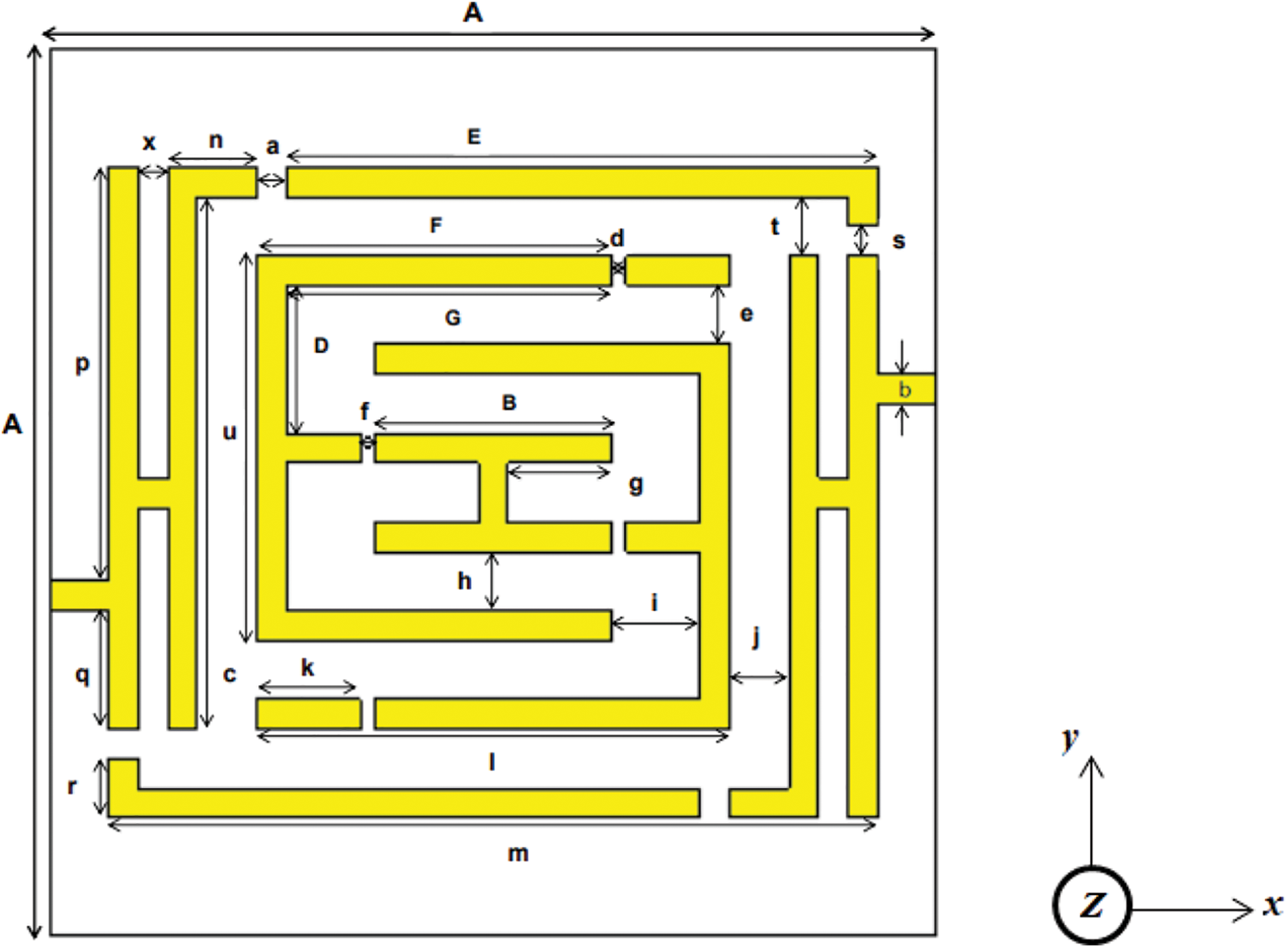
Figure 1: The proposed unit cell structure
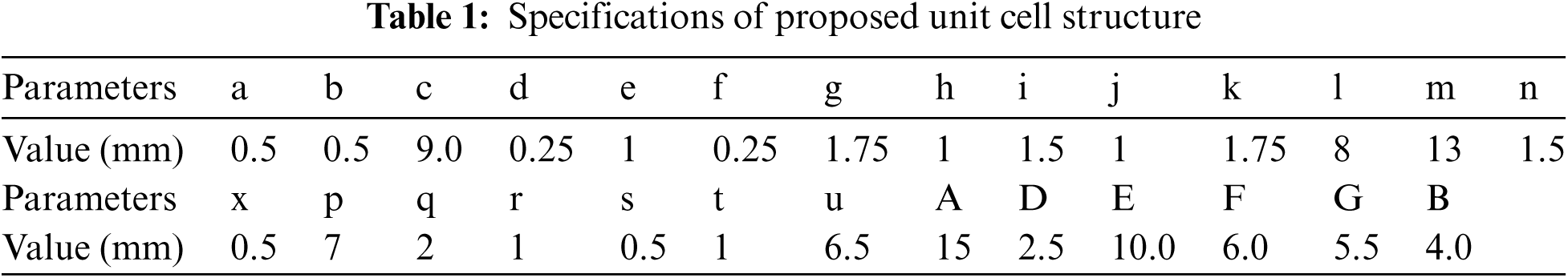
The copper resonators are composed on a dielectric substrate material. The substrate material's length and width are kept A= 15 mm and the width of all copper strips is kept at 0.5 mm. Initially, the structure has been designed on an FR-4 substrate (dielectric constant is 4.3 and loss tangent is 0.025) material of thickness 1.6 mm, then the FR-4 has been replaced by the Rogers RO 3010 substrate (dielectric constant is 10.2 and loss tangent is 0.002) material and analyzed for better results. For FR-4, the effective medium ratio (EMR) is obtained at 5.53, whereas for the Rogers RO 3010 material, it is 8.06. The EMR for the proposed unit cell has been calculated by using the equation: EMR= λ/L, where λ represents the wavelength and L represents the length of the proposed unit cell. For perfect metamaterial operation, the EMR should be kept more than 4 [37] to ensure proper metamaterial operation in bulk context Figs. 2a–2e demonstrates the stepwise design procedure of the unit cell structure and Fig. 2f shows the back view of the design structure. First, in step-1 mutually connected double H shape 10 mm apart from each other has been applied shows in Fig. 2a. Then an interconnected double E shape has been applied in the middle of the structure in step 2. The inner shape is 1 mm apart from the outer shape on every side shown in Fig. 2b. In step 3, the split gaps of 0.25 mm have been created on the double E shape shown in Fig. 2c. In Fig. 2d, the split gaps of 0.5 mm have been created on the double H shape. The design procedure has been reached to the final proposed design by adding copper strips of length 1 mm with the two-outer side of the outer H-shaped ring along with the X-axis.
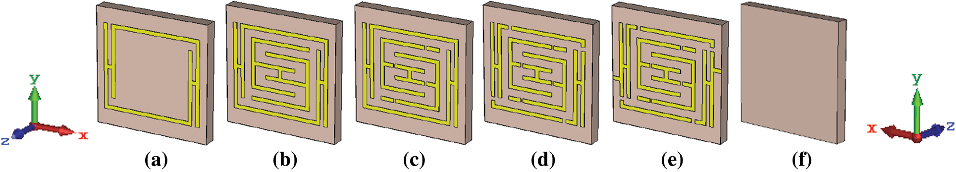
Figure 2: Stepwise design procedure of unit cell in 3D view, (a) step-1 (b) step-2 (c) step-3 (d) step-4 (e) final design of the proposed structure (f) back view of the unit cell
An equivalent circuit model is formulated to verify the design structure and estimate the operating frequency of the proposed metamaterial unit cell as shown in Fig. 3a. Such metamaterial structure includes passive LC circuits with a resonant frequency:
Figure 3: (a) Equivalent circuit model of the proposed unit cell and (b) Simulation geometry of the proposed structure in Z-axis field excitation
where L and C stand at generally structural inductance and capacitance. The current induced in the metal strip creates inductance and the split gap between two metal strips causes capacitance in the metamaterial design [38]. In the structure, copper strips of the unit cell are thus considered as inductance (L) and split gaps on the metal strips are considered as capacitance (C). Following a Quasi-Static theory, the total capacitance between the gaps is frequently stated as:
where
So, for the proposed Double-E-Triple-H-Shaped resonator, the resonant frequency is:
where the inductance for the proposed structure can be calculated as:
And the equivalent capacitance can be demonstrated as:
where,
T=thickness of substrate material = 1.6 mm. A summary of the above equations is available in [3,39]. By using Eqs. (4) and (5), the calculated value of inductance would be,
2.3 Simulation Setup and Methodology
The commercially available CST Microwave Studio simulation software works on the principle of finite integration technique (FIT) is utilized to investigate the performance and calculate the proposed unit cell's S-parameters. Simulation and analysis approaches are adopted from reference [40]. The simulation geometry for the unit cell structure in Z-axis wave propagation is depicted in Fig. 3b. To ensure the proper simulation setup with perfect boundary conditions, the structure was excited by transverse electromagnetic (TEM) wave taking perfect electric-magnetic (PEM) boundary conditions perpendicular to the excitation field. The perfect electric conductor (PEC.) and perfect magnetic conductor (PMC) boundary were taken through X-axis and Y-axis respectively for Z-axis field excitation, and for X-axis field excitation, PEC and PMC boundary were taken through Y-axis and Z-axis respectively. The frequency range was chosen 1-6 GHz to acquire the best result from the designed structure and the frequency domain analysis was considered. Among the several existing methods, the Nicolson-Ross-Weir methodology referenced in [41,42] was adopted to extract the effective medium parameters of the designed structure from the S-parameter simulation results. The simplified formulas for effective parameters extraction are,
where,
d = Substrate thickness.
k0 = Wave number.
η = Refractive index.
3 Results Analysis and Discussion
3.1 Stepwise Evaluation of the Proposed Structure
The designed structure has been evaluated step by step up to the final design of the unit cell. Tab. 2 demonstrates the effective parameters for the different design steps of the proposed structure. To make the proper evaluation of the structure the Rogers RO 3010 substrate has been considered.
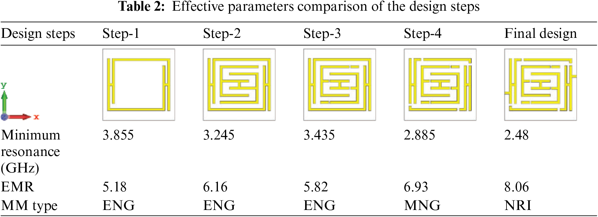
Fig. 4 demonstrates the unit cell structure's performance compared to the previous design steps made on the transmission resonance curve S21 and reflection coefficient curve S11. The transmission resonance curve shows more sharpness with minimum resonance, high magnitude, and maximum EMR compare to the step-1 to step-4. In the table, we can see that the minimum resonance for the design step-1 is 3.855 GHz with a maximum EMR 5.18, and the type of the metamaterial is epsilon negative (ENG). The design has been modified to get a better result and gradually the better performances have been acquired. The final proposed design shows the best performance with negative refractive index (NRI) metamaterial properties at the minimum resonance of 2.48 GHz and the maximum EMR 8.06 is achieved at this frequency. It also shows the ENG metamaterial properties at the resonance frequency of 3.805 GHz. The magnitude of the resonance curve S21 for the proposed design is −53.94 dB at 2.48 GHz and −50.03 dB at 3.805 GHz, which is far greater than that are for design step-1 to 4.
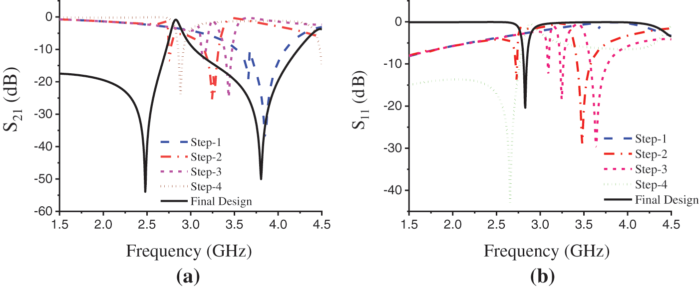
Figure 4: (a) The transmission coefficient (S21) and (b) reflection coefficient (S11) view for the design steps
3.2 Simulated Results Using FR-4 and RO 3010 Substrate
The simulated results for the proposed structure for two different substrates considering a thickness of 1.6 mm are discussed here based on Z-axis and X-axis field excitation.
In the Z-axis wave propagation, the structure exhibits Epsilon-Negative (ENG) metamaterial properties within S-band and Mue-Negative (MNG) metamaterial properties within C-band with EMR 6.45 for RO 3010 substrate and EMR 4.33 for FR-4 substrate.
Fig. 5 shows the simulation results for FR-4 substrate in the Z-axis field excitation. The transmission coefficient (S21) in Fig. 5a shows the transmission resonance at the frequency of 4.615 GHz with a magnitude of −24.15 dB. The EMR has been found 4.33 for FR-4 substrate in the Z-axis wave propagation. The frequency vs. permittivity curve in Fig. 5b depicts a positive real value of 18.12 for permittivity at the resonance frequency of 4.615 GHz. The effective permeability curve in Fig. 5c and refractive index curve in Fig. 5d demonstrate negativity and positivity for permeability and refractive index with the real values of −24.78 and 28.94 at this frequency. Thus, in Z-axis field excitation the designed structure shows MNG metamaterial properties within the C-band of microwave spectra.
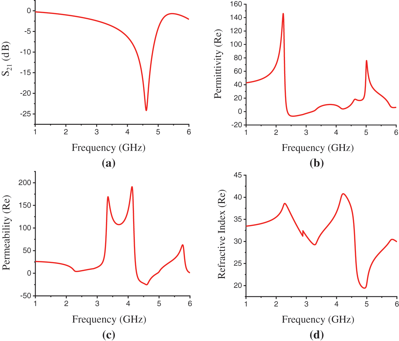
Figure 5: FR-4 Substrate results. (a) Transmission Resonance (S21), (b) Permittivity(ε) (Real) curve, (c) Permeability(μ) (Real) curve, (d) Refractive index (η) (Real) curve in Z-axis propagation
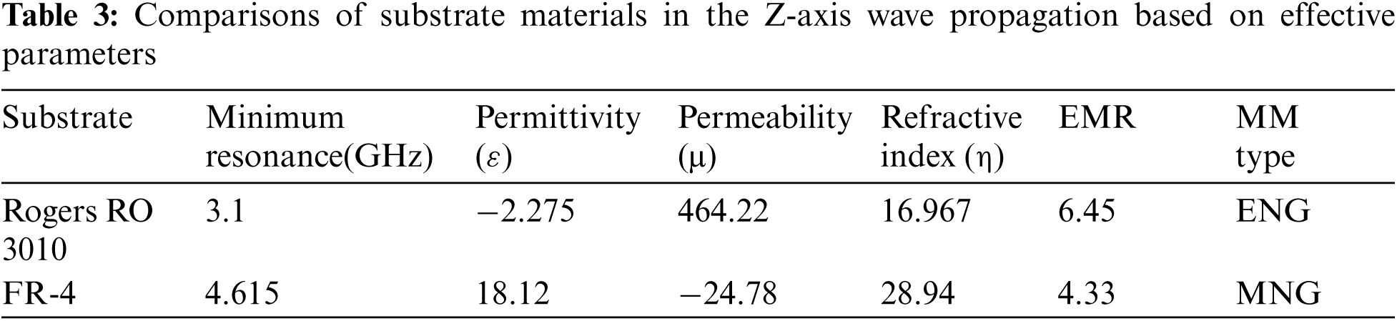
Fig. 6 shows the simulation results for RO 3010 substrate in the Z-axis field excitation. The transmission coefficient (S21) in Fig. 6a shows the transmission resonance at the frequency of 3.1, 4.305 and 5.055 GHz with the magnitude of −40.97, −25.19, and −21.43 dB. The EMR has been found 6.45 for RO 3010 substrate in the Z-axis wave propagation. The frequency vs. permittivity curve in Fig. 6b depicts a negative real value of −2.275 for permittivity at the resonance frequency of 3.1 GHz. The effective permeability curve in Fig. 6c and refractive index curve in Fig. 6d demonstrate positivity for permeability and refractive index with the real values of 464.22 and 16.967 at this frequency. Thus, the structure shows ENG metamaterial properties at the resonance frequency of 3.1 GHz for the Z-axis wave Propagation. At the resonance frequency of 4.305 GHz that is within the C-band, the frequency vs. permeability curve shown in Fig. 6c exhibits the negative real value of −36.61 for permeability. And, the positive real values of effective permittivity and refractive index at this frequency have shown in Figs. 6b and 6d are, 14.03 and 32.99 respectively. At the resonance of 5.055 GHz the permittivity, permeability, and refractive index values are found 24.27, −12.21, and 28.05.
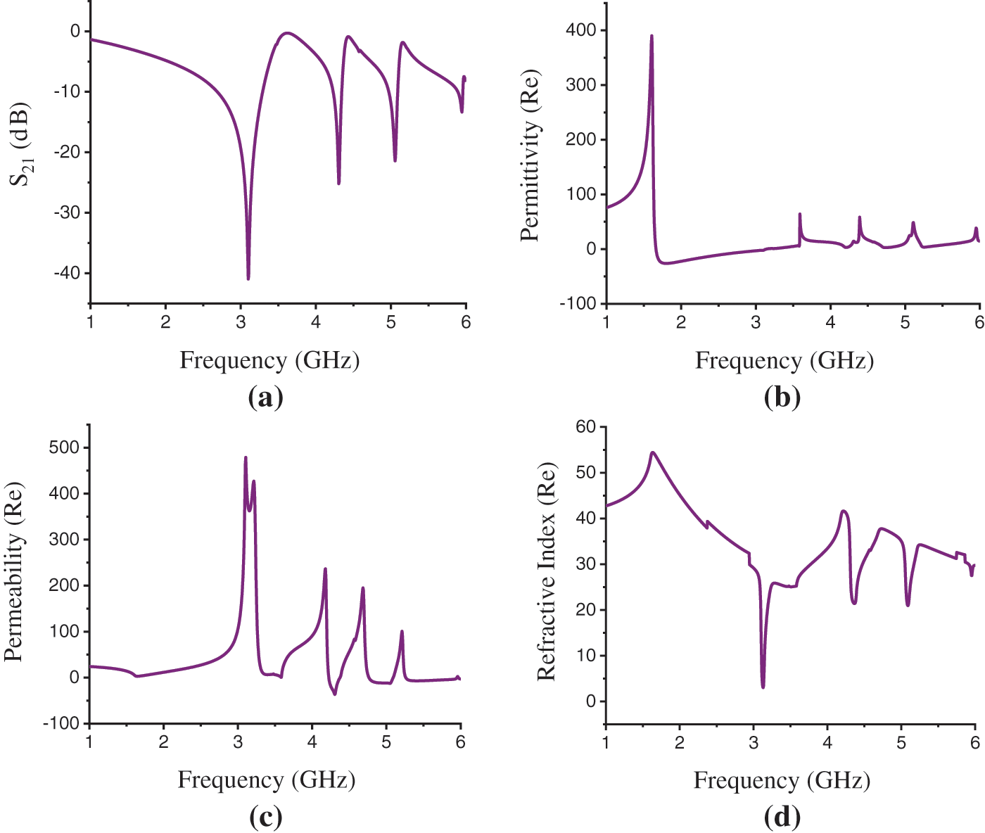
Figure 6: Rogers RO 3010 Substrate results. (a) Transmission resonance (S21), (b) Permittivity(ε) (Real) curve, (c) Permeability(μ) (Real) curve, (d) Refractive index (η) (Real) curve in Z-axis propagation
As the proposed structure exhibits the MNG metamaterial properties at the resonance of 4.305 and 5.055 GHz, the material thus is characterized as Mue-Negative (MNG) or Single-Negative (SNG) metamaterial within the C-band of microwave spectra. The overall comparisons of substrate materials based on different effective parameters for Z-axis field excitation are shown in Tab. 3.
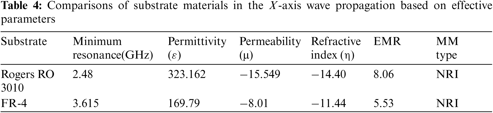
The proposed structure shows the Negative Refractive Index (NRI) and Epsilon-Negative (ENG) metamaterial properties within S-band and Epsilon-Negative (ENG) metamaterial properties within C-band in the X-axis wave propagation. The maximum EMR 8.06 is achieved in this wave propagation for Rogers RO 3010 substrate and EMR 5.53 is found for FR-4 substrate. The simulation results for FR-4 substrate in the X-axis field excitation are presented in Fig. 7. The transmission coefficient (S21) in Fig. 7a shows the transmission resonance at the frequency of 3.615 and 5.595 GHz with the magnitude of −41.75 and −35.599 dB. The EMR has been found 5.53 for FR-4 substrate in the X-axis wave propagation. The frequency vs. permittivity curve in Fig. 7b depicts a positive real value of 169.79 for permittivity at the resonance frequency of 3.615 GHz. The effective permeability curve in Fig. 7c and refractive index curve in Fig. 7d demonstrate negativity for permeability and refractive index with the real values of −8.01 and −11.44 at this frequency. Thus, the structure shows NRI metamaterial properties at the resonance frequency of 3.615 GHz for the X-axis wave propagation. At the resonance frequency of 5.595 GHz that is within the C-band, the frequency vs. permittivity curve shown in Fig. 7b exhibits the negative real value of −79.43 for permittivity. And, the positive real values of effective permeability and refractive index at this frequency have shown in Figs. 7c and 7d are, 5.44 and 8.00 respectively.
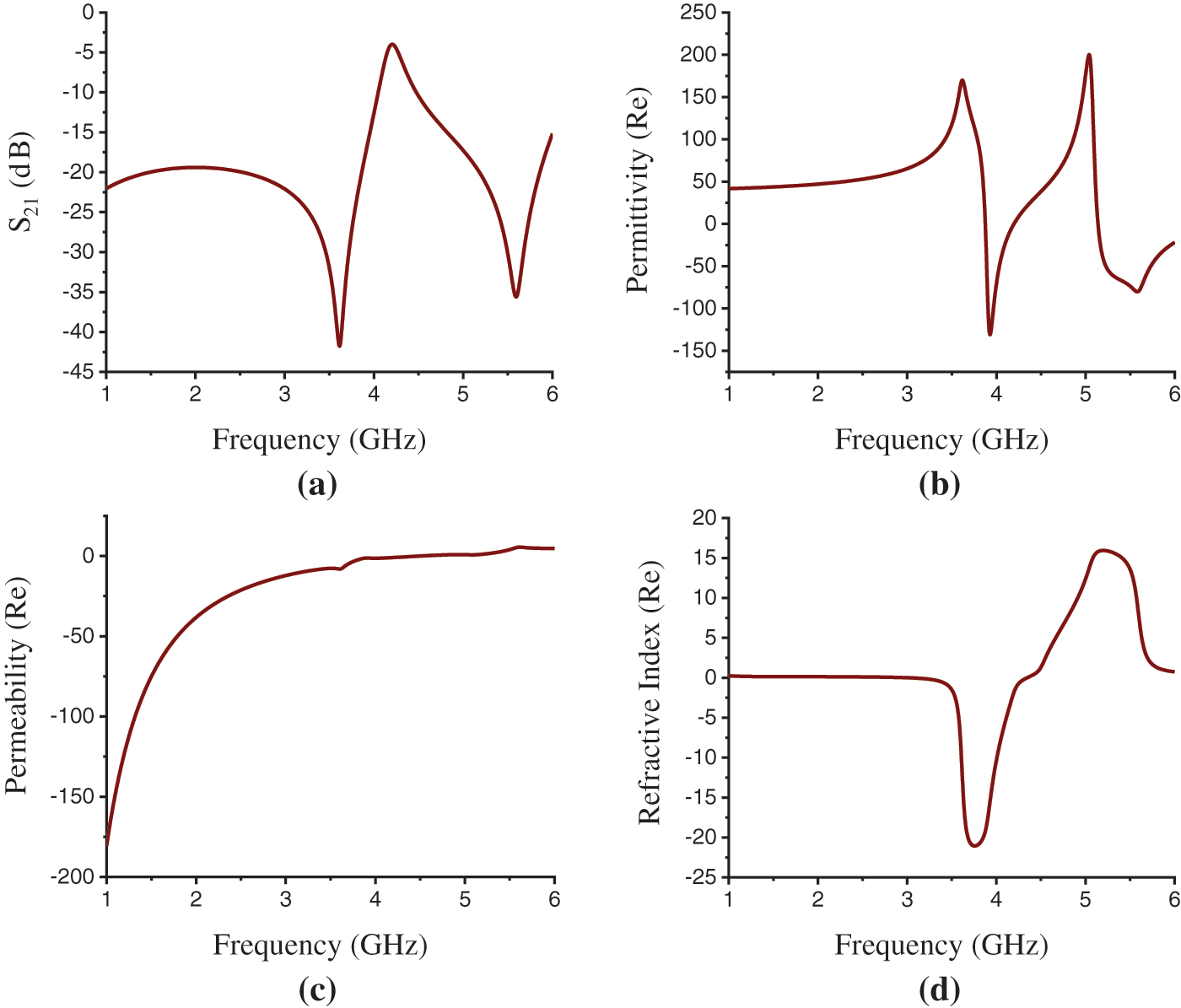
Figure 7: FR-4 Substrate results. (a) Transmission resonance (S21), (b) Permittivity(ε) (Real) curve, (c) Permeability(μ) (Real) curve, (d) Refractive index (η) (Real) curve in X-axis propagation
The simulation results for Rogers RO 3010 in the X-axis field excitation are shown in Fig. 8. The transmission coefficient (S21) in Fig. 8a shows the transmission resonance at the frequency of 2.48 and 3.805 GHz with the magnitude of −53.94 and −50.03 dB. The maximum EMR 8.06 is found here for RO 3010 in the X-axis wave propagation. Fig. 8b shows that the effective permittivity curve at the resonance frequency of 2.48 GHz does not show negativity and the real value for effective permittivity is 323.162. The effective permeability curve in Fig. 8c and the refractive index curve in Fig. 8d demonstrate negativity at this frequency. The real values for permeability and refractive index at the resonance frequency of 2.48 GHz are −15.549 and −14.40. Now, it can be concluded that, at a resonance frequency of 2.48 GHz, the structure shows NRI metamaterial properties and the material thus can be identified as Negative Refractive Index (NRI) metamaterial. At the resonance frequency of 3.805 GHz, only the effective permittivity curve in Fig. 8b depicts that the permittivity is negative with the real value of −185.926. The other two-parameter curves, frequency vs. permeability in Fig. 8c and frequency vs. refractive index in Fig. 8d exhibit positive real values of 9.986 and 11.55 for permeability and refractive index at this frequency. So, at a resonance frequency of 3.805 GHz, the structure is characterized as a Single Negative (SNG) or ENG metamaterial. Tab. 4 presents the overall comparisons of substrate materials based on different effective parameters for X-axis field excitation.
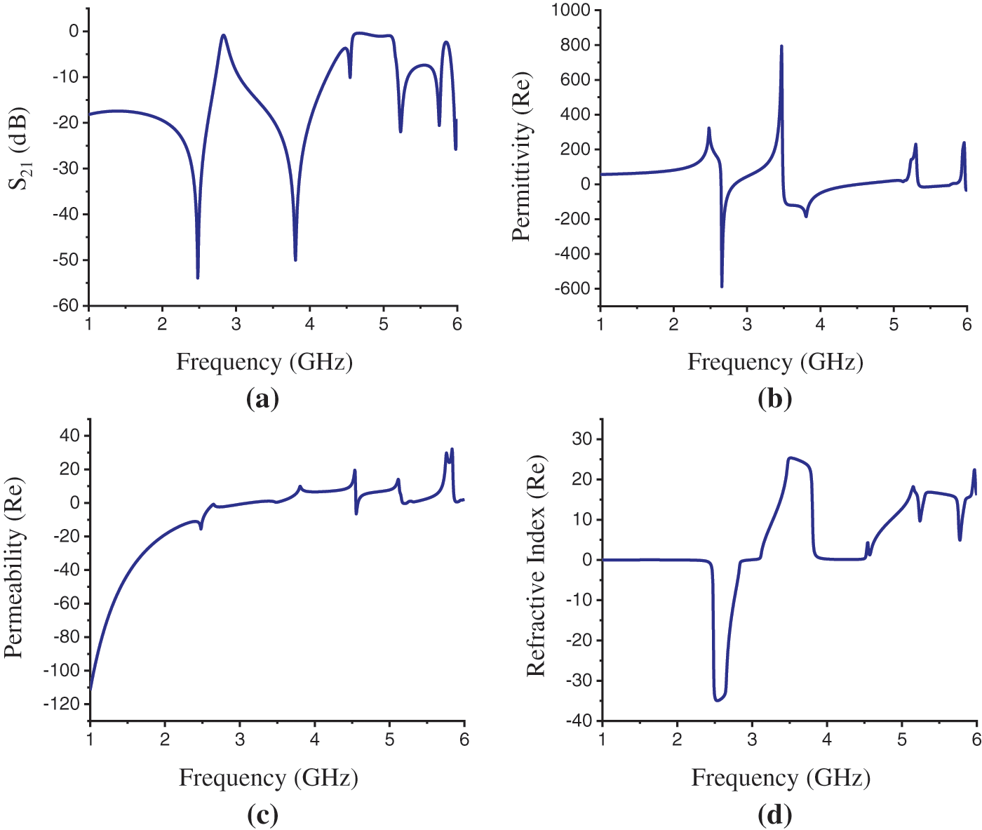
Figure 8: Rogers RO 3010 Substrate results. (a) Transmission resonance (S21), (b) Permittivity(ε) (Real) curve, (c) Permeability(μ) (Real) curve, (d) Refractive index (η) (Real) curve in X-axis propagation
3.3 Effect of Rogers RO 3010 Dielectric Substrate Thickness
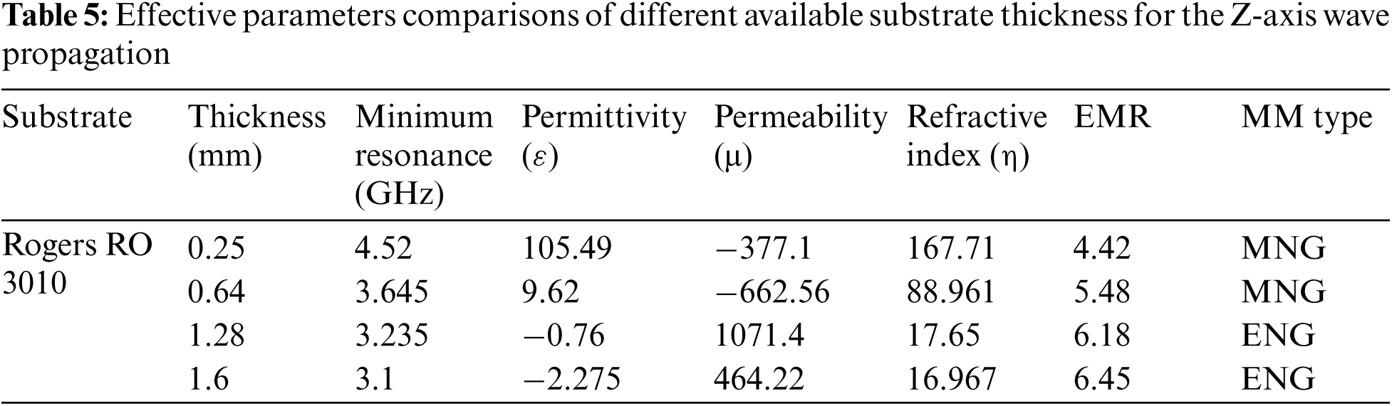
The proposed design structure has been analyzed for a different commercially available substrate thickness of Rogers RO 3010 substrate material. The effect of substrate thickness change on transmission resonance and different effective parameters of the structure has been considered. The available thickness of 0.25, 0.64, 1.28, and 1.6 mm has been taken for this performance analysis. Fig. 9a depicts the substrate thickness changing effect on transmission resonance and Tab. 5 shows the comparison of the effective parameters of different available Rogers RO 3010 substrate material thickness for the Z-axis wave propagation. In this propagation, the metamaterial properties change with the substrate thickness change, that is, for 0.25 and 0.64 mm thickness the design shows MNG metamaterial properties. But, for 1.28 and 1.6 mm thickness the structure shows ENG properties in minimum resonance.
There is a significant effect has been seen on transmission resonance, that is the effective medium ratio (EMR) increases for an increase in substrate thickness. The maximum EMR achieved for Z-axis wave propagation is 6.45 for the thickness of 1.6 mm. In the figure thus the transmission resonance is shifting downward with the increase in substrate thickness.
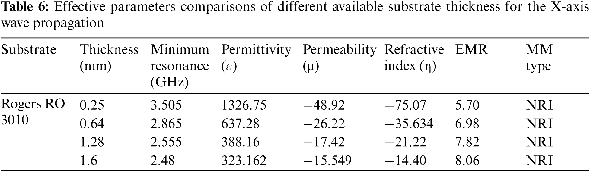
Fig. 9b depicts the thickness changing effect on transmission resonance for the X-axis wave propagation. Tab. 6 demonstrates the comparison of the effective parameters for different substrate thickness considering X-axis wave propagation. In this propagation, the metamaterial properties are not changing for different substrate thickness and being unchanged with NRI properties. But the transmission resonance shifts downward with the increase in substrate thickness shown in Fig. 9b. The effective medium ratio (EMR) increases for an increase in substrate thickness, and a maximum EMR 8.06 is achieved for a substrate thickness of 1.6 mm in the X-axis wave propagation.
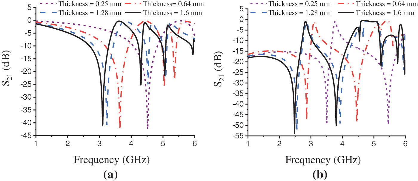
Figure 9: Effect on transmission resonance (S21) for different available Rogers RO 3010 substrate material thickness. (a) Z-axis wave propagation and (b) X-axis wave propagation
3.4 Permittivity Sensor on Simulation Environment
The proposed unit cell is optimized for the permittivity sensing applications of solid or liquid materials in the simulation environment. A simulation arrangement for permittivity measurement where a SUT (Sample Under Test) is placed on the unit cell's resonator plane is depicted in Fig. 10a. The idea of permittivity measurement of solid or liquid material by placing SUT on metamaterial sensor in a simulation environment is found from the previous work referenced in [43]. Here, we have taken the SUT material of thickness 1 mm, length and width are the same as the dielectric substrate of the sensor unit cell. To evaluate the unit cell's permittivity sensitivity through simulation, we have added a parametric sweep for permittivity of the SUT from 2 to 10 with a step size of 2.
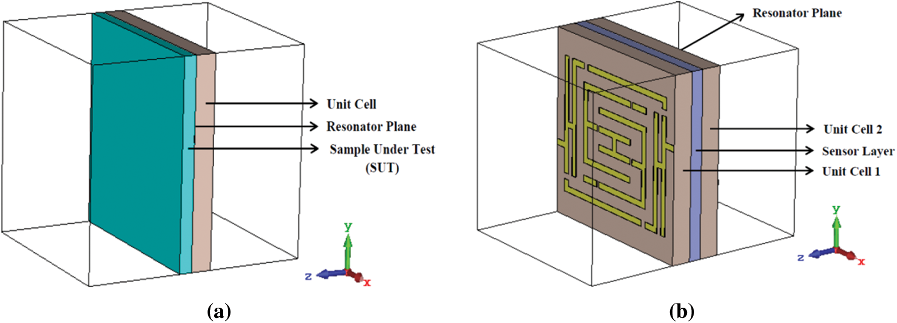
Figure 10: Simulation setup for (a) permittivity sensor and (b) pressure sensor using proposed metamaterial unit cell
The simulated result is made on transmission resonance S21 at Figs. 11a and 11b illustrates the resonance frequency shifting for the sensor unit cell with the permittivity changing of the SUT material for the Z-axis and X-axis field excitation respectively. The resonance shifting in the figure shows an inversely proportional relation to the permittivity changing of the SUT material; with the increase of permittivity the resonance frequency decreases. The sensor unit cell shows a good permittivity sensing ability with high sensitivity in the simulation environment. The average resonance shift on S21 for X-axis and Z-axis wave propagation is found to be 0.113 GHz/Step and 0.138 GHz/Step respectively, which are a notable number of shifts compared to the other existed permittivity sensors. Thus, the unit cell can be used in S and C-band permittivity sensing applications for solid or liquid materials.
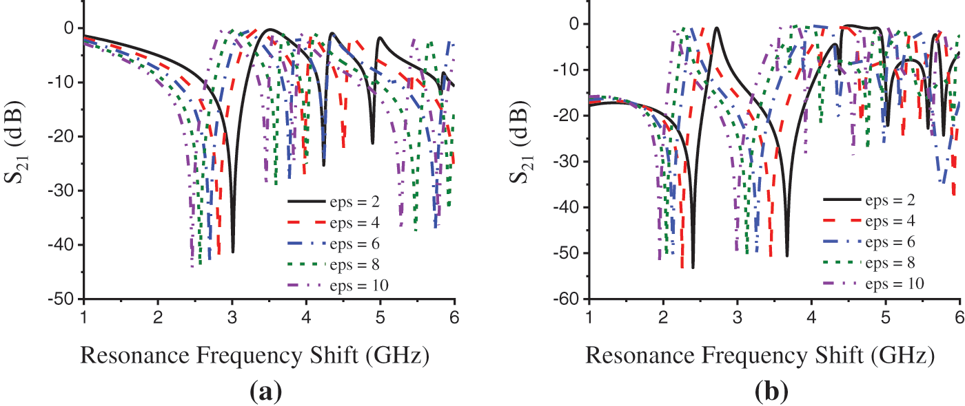
Figure 11: Permittivity sensitivity (resonance frequency shift concerning SUT permittivity) of the unit cell in simulation. (a) Z-axis excitation and (b) X-axis excitation
3.5 Pressure Sensor on Simulation Environment
The proposed structure is also optimized for the pressure sensing applications within S-band along with permittivity sensing applications in the simulation environment. A simulation arrangement for pressure sensing application is depicted in Fig. 10b, where two-unit cells are sandwiched with a sensor layer in middle. The sensor layer used here in the middle is the air cushion. The idea of a pressure sensor with sandwiched unit cells having a sensor layer in the middle and using air cushion as sensor layer are found from the previous works referenced in [44,45].
To evaluate the pressure sensitivity of the unit cell through simulation, we have considered the sensor layer thickness gradually increasing from 0.0 to 0.8 mm with taking 0.2 mm/observation. To perform the increase of sensor layer thickness we have made a parametric sweep on sensor layer thickness by taking a step width of 0.2 mm. Figs. 12a and 12b depict the simulated result for the sensor's pressure sensitivity within C and S-band respectively, that are made on S21. An increase in sensor layer means increasing the distance between two-unit cells works as two plates of a capacitor. As capacitance is inversely proportional to the distance, with the increase in distance the capacitance decreases that makes resonant frequency shift upward (according to the Eq. (1)
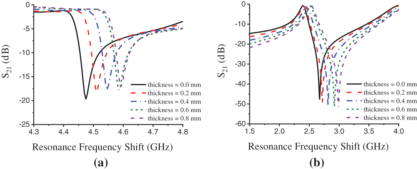
Figure 12: Pressure sensitivity (resonance frequency shift concerning sensor layer thickness) of the unit cell in simulation. (a) within C-band and (b) within S-band
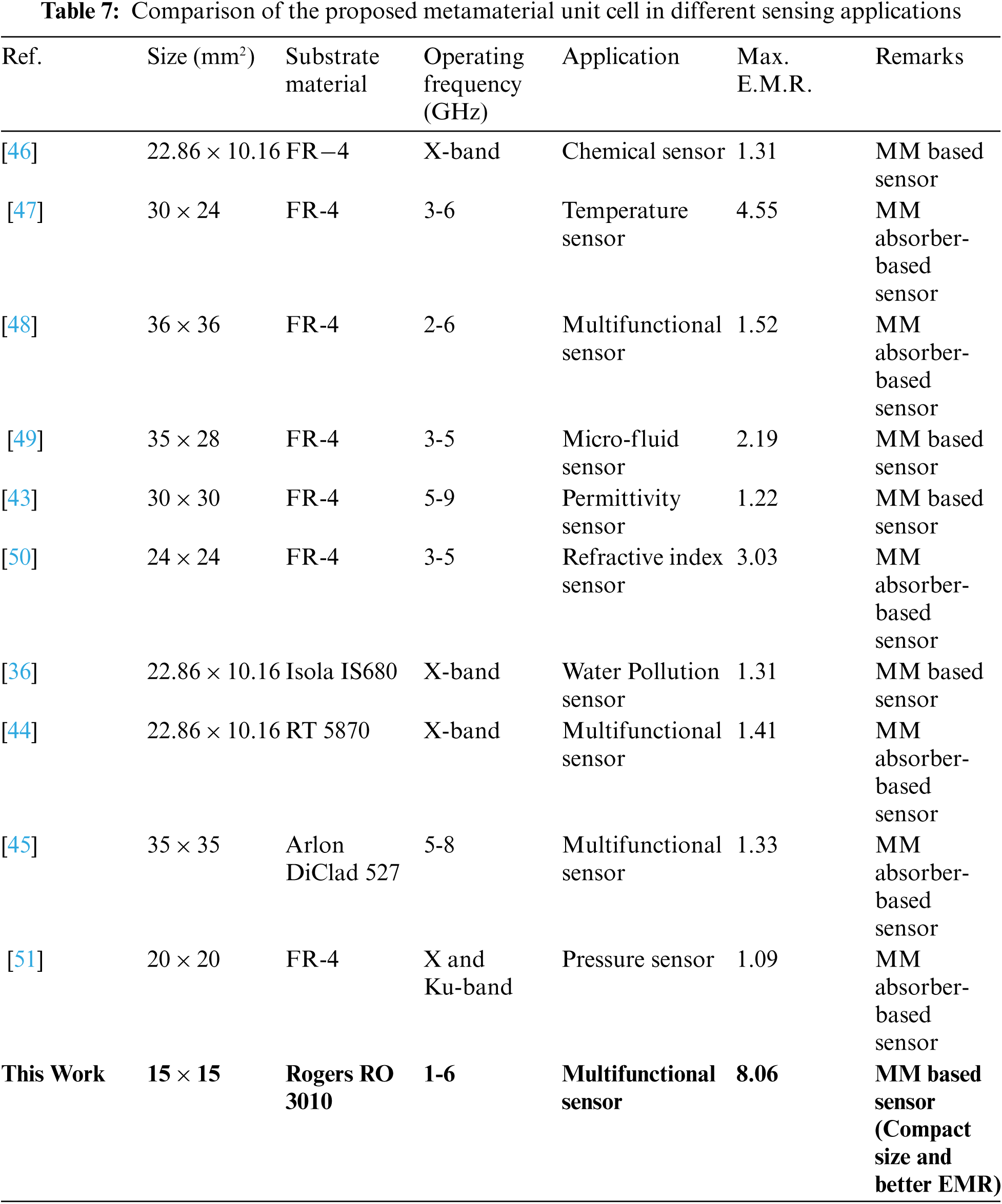
Thus, the figures depict a proportional relation of resonance frequency shifting to the change in sensor layer thickness that is with the increase of layer thickness the resonance frequency also increases. The average resonance shift on S21 is found 0.0788 GHz/observation shown in Fig. 12a and 0.0288 GHz/observation shown in Fig. 12b. As the unit cell shows a good pressure sensing ability with high sensitivity, the unit cell thus can be used in S and C-band pressure sensing applications. Tab. 7 demonstrates a comparison of the proposed metamaterial unit cell structure with some existed metamaterial unit cells in different sensing applications.
In this article, a new metamaterial unit cell structure is investigated for sensing applications. To identify the criteria for the proposed unit cell, a parametric analysis was performed for FR-4 and Rogers RT-3010 substrate material. The proposed design shows the NRI and ENG metamaterial properties within S-band and ENG properties within C-band for the X-axis wave propagation. The maximum EMR 8.06 is achieved in this wave propagation for Rogers RO 3010 substrate material and EMR 5.53 is found for the FR-4 substrate material. In the Z-axis wave propagation, the structure exhibits ENG metamaterial properties within S-band and MNG metamaterial properties within C-band with EMR 6.45 for RO 3010 substrate material and EMR 4.33 for FR-4 substrate material. Further analysis has been done by changing the thickness of the substrate of Rogers RO 3010, and only at 1.6 mm thickness, it displays EMR 8.06 with NRI properties. The numerical result was verified mathematically for the metamaterial operations for Rogers RO 3010 substrate material in the X-axis propagation. At last, we have simulated the structure (using Rogers RO 3010 substrate of thickness 1.6 mm) for permittivity sensing applications of solid or liquid material and pressure sensing applications. The average resonance shift on S21 is found 0.0788 and 0.0288 GHz per observation for the pressure sensor, and the average resonance shift on S21 is seen at 0.113 and 0.138 GHz per step permittivity change for the permittivity sensor through numerical study. Thus, the new metamaterial has the potential for communication and satellite applications within S-band and C-band considering the permittivity and pressure sensing applications.
Funding Statement: This work was supported by the Universiti Kebangsaan Malaysia, Malaysia research grant code GUP-2019-005.
Conflicts of Interest: The authors declare that they have no conflicts of interest to report regarding the present study.
1. R. Marqués, F. Martin and M. Sorolla, “Metamaterials with negative parameters: Theory, design, and microwave applications,” in Wiley Series In Microwave and Optical Engineering, 1st ed., vol. 183, New York: Wiley, 2008. [Google Scholar]
2. J. B. Pendry, D. Schurig and D. R. Smith, “Controlling electromagnetic fields,” Science, vol. 312, no. 5781, pp. 1780–1782, 2006. [Google Scholar]
3. J. B. Pendry, A. J. Holden, D. J. Robbins and W. J. Stewart, “Magnetism from conductors and enhanced nonlinear phenomena,” IEEE Transactions on Microwave Theory and Techniques, vol. 47, no. 11, pp. 2075–2084, 1999. [Google Scholar]
4. R. A. Shelby, D. R. Smith and S. Schultz, “Experimental verification of a negative index of refraction,” Science, vol. 292, no. 5514, pp. 77–79, 2001. [Google Scholar]
5. J. B. Pendry, “Negative refraction makes a perfect lens,” Physical Review Letters, vol. 85, no. 18, pp. 3966, 2000. [Google Scholar]
6. Z. Jacob, L. V. Alekseyev and E. Narimanov, “Optical hyperlens: Far-field imaging beyond the diffraction limit,” Optics Express, vol. 14, no. 18, pp. 8247–8256, 2006. [Google Scholar]
7. Z. Liu, H. Lee, Y. Xiong, C. Sun and X. Zhang, “Far-field optical hyperlens magnifying sub-diffraction-limited objects,” Science, vol. 315, no. 5819, pp. 1686–1686, 2007. [Google Scholar]
8. I. I. Smolyaninov, Y. J. Hung and C. C. Davis, “Magnifying superlens in the visible frequency range,” Science, vol. 315, no. 5819, pp. 1699–1701, 2007. [Google Scholar]
9. V. G. Veselago, “Reviews of topical problems: The electrodynamics of substances with simultaneously negative values of\epsilon and μ,” Soviet Physics Uspekhi, vol. 10, no. 4, pp. R04, 1968. [Google Scholar]
10. X. Jing, D. Feng, Y. Tian, M. Li, C. Chu et al., “Design of two invisibility cloaks using transmissive and reflective metamaterial-based multilayer frame microstructures,” Opt. Express, vol. 28, no. 24, pp. 35528, 2020. [Google Scholar]
11. S. Mahmud, M. Karim, S. S. Islam, M. I. K. Shuvo, T. Akter et al., “A Multi-band near perfect polarization and angular insensitive metamaterial absorber with a simple octagonal resonator for visible wavelength,” IEEE Access, vol. 9, pp. 117746–117760, 2021. [Google Scholar]
12. N. Gupta, J. Saxena, K. S. Bhatia and N. Dadwal, “Design of metamaterial-loaded rectangular patch antenna for satellite communication applications,” Iran. J. Sci. Technol. - Trans. Electr. Eng, vol. 43, pp. 39–49, 2019. [Google Scholar]
13. T. Alam, A. F. Almutairi, M. Samsuzzaman, M. Cho and M. T. Islam, “Metamaterial array based meander line planar antenna for cube satellite communication,” Sci. Rep, vol. 11, no. 1, pp. 1–12, 2021. [Google Scholar]
14. M. M. K. Shuvo, M. I. Hossain, S. Rahman, S. Mahmud, S. S. Islam et al., “A Wide-angle, enhanced oblique incidence, bend-able metamaterial absorber employed in visible region with a Sun shape resonator,” In IEEE Access, vol. 9, pp. 126466–126480, 2021. [Google Scholar]
15. A. Salleh, C. Yang, T. Alam, M. Singh, M. Samsuzzaman et al., “Development of microwave brain stroke imaging system using multiple antipodal vivaldi antennas based on raspberry Pi technology,” J. Kejuruterran, vol. 32, pp. 1–6, 2020. [Google Scholar]
16. M. Alibakhshikenari, B. S. Virdee, P. Shukla, N. O. Parchin, L. Azpilicuata et al., “Metamaterial-inspired antenna array for application in microwave breast imaging systems for tumor detection,” IEEE Access, vol. 8, pp. 174667–174678, 2020. [Google Scholar]
17. H. Kind, H. Yan, B. Messer, M. Law and P. Yang, “Nanowire ultraviolet photodetectors and optical switches,” Advanced Materials, vol. 14, no. 2, pp. 158–160, 2002. [Google Scholar]
18. M. Wuttig and N. Yamada, “Phase-change materials for rewriteable data storage,” Nature Materials, vol. 6, no. 11, pp. 824–832, 2007. [Google Scholar]
19. R. Singh, C. Rockstuhl, F. Lederer and W. Zhang, “Coupling between a dark and a bright eigenmode in a terahertz metamaterial,” Physical Review B, vol. 79, no. 8, pp. 085111, 2009. [Google Scholar]
20. M. Alibakhshikenari, B. S. Virdee, P. Shukla, Y. Wang, L. Azpilicuata et al., “Impedance bandwidth improvement of a planar antenna based on metamaterial-inspired T-matching network,” IEEE Access, vol. 9, pp. 67916–67927, 2021. [Google Scholar]
21. M. Alibakhshikenari, B. S. Virdee, A. A. Althuwayb, S. Aissa, C. H. See et al., “Study on on-chip antenna design based on metamaterial-inspired and substrate-integrated waveguide properties for millimetre-wave and THz integrated-circuit applications,” J. Infrared, Millimeter, Terahertz Waves, vol. 42, no. 1, pp. 17–28, 2021. [Google Scholar]
22. D. Wang, L. Ran, H. Chen, M. Mu, J. A. Kong et al., “Experimental validation of negative refraction of metamaterial composed of single side paired S-ring resonators,” Applied Physics Letters, vol. 90, no. 25, pp. 254103, 2007. [Google Scholar]
23. B. Gallas, K. Robbie, R. Abdeddaïm, G. Guida, J. Yang et al., “Silver square nanospirals mimic optical properties of U-shaped metamaterials,” Optics Express, vol. 18, no. 16, pp. 16335–16344, 2010. [Google Scholar]
24. M. R. I. Faruque and M. T. Islam, “Novel triangular metamaterial design for electromagnetic absorption reduction in human head,” Progress in Electromagnetics Research, vol. 141, pp. 463–478, 2013. [Google Scholar]
25. E. Ekmekçi and G. Turhan-Sayan, “Investigation of effective permittivity and permeability for a novel v-shaped metamaterial using simulated s-parameters,” in 5th Int. Conf. on Electrical and Electronics Engineering, sn, Bursa, Turkey, pp. 251–254, 2007. [Google Scholar]
26. K. Sinha, S. S. Islam and M. J. Hossain, “A combined WU-shaped NRI metamaterial for dual band microwave application,” Universal Journal of Electrical and Electronic Engineering, vol. 7, no. 2, pp. 81–87, 2020. [Google Scholar]
27. A. R. Azeez, T. A. Elwi and Z. A. A. AL-Hussain, “Design and analysis of a novel concentric rings based crossed lines single negative metamaterial structure,” Engineering Science and Technology, an International Journal, vol. 20, no. 3, pp. 1140–1146, 2017. [Google Scholar]
28. S. S. Islam, M. R. I. Faruque, M. T. Islam and T. Alam, “A new mu-negative metamaterial,” in 2015 2nd Int. Conf. on Electrical Information and Communication Technologies (EICT), Khulna, Bangladesh, IEEE, pp. 269–272, 2015. [Google Scholar]
29. A. Sarkar, A. H. Naqvi and S. Lim, “(40 to 65) GHz higher order mode microstrip-based dual band dual beam tunable leaky-wave antenna for millimeter wave applications,” IEEE Transactions on Antennas and Propagation, vol. 68, no. 11, pp. 7255–7265, 2020. [Google Scholar]
30. M. Alibakhshikenari, B. S. Virdee, C. H. See, R. A. Abd-Alhameed, F. Falcone et al., “High-isolation leaky-wave array antenna based on CRLH-metamaterial implemented on siw with ± 30o frequency beam-scanning capability at millimetre-waves,” Electronics, vol. 8, no. 6, pp. 1–15, 2019. [Google Scholar]
31. S. S. Islam, M. R. I. Faruque, M. T. Islam and M. T. Ali, “A new wideband negative refractive index metamaterial for dual-band operation,” Applied Physics A, vol. 123, no. 4, pp. 252, 2017. [Google Scholar]
32. M. I. Hossain, M. R. I. Faruque and M. T. Islam, “Design and analysis of double negative metamaterial for microwave s-band,” in 2015 IEEE 12th Malaysia Int. Conf. on Communications (MICC), Kuching, Malaysia, IEEE, pp. 315–318, 2015. [Google Scholar]
33. D. Wu, C. Liu, Y. Liu, L. Yu, Z. Yu et al., “Numerical study of an ultra-broadband near-perfect solar absorber in the visible and near-infrared region,” Optics Letters, vol. 42, no. 3, pp. 450–453, 2017. [Google Scholar]
34. D. Xiao, Q. Liu, L. Lei, Y. Sun, Z. Ouyang et al., “Coupled resonance enhanced modulation for a graphene-loaded metamaterial absorber,” Nanoscale Research Letters, vol. 14, no. 1, pp. 1–6, 2019. [Google Scholar]
35. G. Kiti, V. Radoni and V. Crnojevi-Bengin, “Soil moisture sensors based on metamaterials,” Songklanakarin Journal of Science and Technology, vol. 34, no. 6, pp. 689–693, 2012. [Google Scholar]
36. M. Bakır, S. Dalgac, E. Unal, F. Karadag, M. Demirci et al., “High sensitive metamaterial sensor for water treatment centres,” Water, Air, & Soil Pollution, vol. 230, no. 12, pp. 1–9, 2019. [Google Scholar]
37. S. S. Islam, M. S. Khan and M. R. I. Faruque, “Design and analysis of modified-split-H-shaped DNG metamaterial for microwave application,” Materials Research Express, vol. 6, no. 12, pp. 125808, 2020. [Google Scholar]
38. N. Dhar, M. A. Rahman and M. A. Hossain, “Design and exploration of functioning of a D-Z shaped SNG multiband metamaterial for L-, S-, and X-bands applications,” SN Applied Science, vol. 2, no. 6, pp. 1–16, 2020. [Google Scholar]
39. D. Knight and R. Rosenbaum, “Grover's’ inductance calculations’ supplementary information and errata, ottery St Mary, Devon, England,” 2012. [Online]. Available: https://hamwaves.com/inductance/doc/knight.2012.pdf. [Google Scholar]
40. T. Meng, G. Savini, C. Leung, G. Zhao and F. Deng, “A CST simulation and performance analysis for a passive façade integratable metamaterials structure,” in 2017 10th UK-Europe-China Workshop on Millimetre Waves and Terahertz Technologies (UCMMT), Liverpool, UK, IEEE, pp. 1–4, 2017. [Google Scholar]
41. A. M. Nicolson and G. F. Ross, “Measurement of the intrinsic properties of materials by time-domain techniques,” IEEE Transaction on Instrumentation and Measurement, vol. 19, pp. 377–382, 1970. [Google Scholar]
42. J. J. Barroso and A. L. De Paula, “Retrieval of permittivity and permeability of homogeneous materials from scattering parameters,” J. Electromagn. Waves Appl., vol. 24, no. 11–12, pp. 1563–1574, 2010. [Google Scholar]
43. A. Raj, A. K. Jha, M. A. H. Ansari, M. J. Akhtar, S. Panda et al., “Metamaterial-inspired microwave sensor for measurement of complex permittivity of materials,” Microwave and Optical Technology Letters, vol. 58, no. 11, pp. 2577–2581, 2016. [Google Scholar]
44. Z. Ozer, A. Mamedov and E. Ozbay, “Metamaterial absorber based multifunctional sensor application,” in IOP Conf. Series: Materials Science and Engineering, Miskolc, Hungary, IOP Publishing, vol. 175, no. 1, pp. 012059, 2017. [Google Scholar]
45. M. Bakır, M. Karaaslan, E. Unal, O. Akgol and C. Sabah, “Microwave metamaterial absorber for sensing applications,” Opto-Electronics Review, vol. 25, no. 4, pp. 318–325, 2017. [Google Scholar]
46. Y. I. Abdulkarim, L. Deng, H. Luo, S. Huang, M. Karaaslan et al., “Design and study of a metamaterial based sensor for the application of liquid chemicals detection,” Journal of Materials Research and Technology, vol. 9, no. 5, pp. 10291–10304, 2020. [Google Scholar]
47. M. Bakır, M. Karaaslan, F. Dinçer, K. Delihacioglu and C. Sabah, “Tunable perfect metamaterial absorber and sensor applications,” Journal of Materials Science: Materials in Electronics, vol. 27, no. 11, pp. 12091–12099, 2016. [Google Scholar]
48. O. Akgol, M. Karaaslan, E. Unal and C. Sabah, “Implementation of a perfect metamaterial absorber into multi-functional sensor applications,” Modern Physics Letters B, vol. 31, no. 15, pp. 1750176, 2017. [Google Scholar]
49. O. Altintas, M. Aksoy, O. Akgol, E. Unal, M. Karaaslan et al., “Fluid, strain and rotation sensing applications by using metamaterial based sensor,” Journal of the Electrochemical Society, vol. 164, no. 12, pp. B567, 2017. [Google Scholar]
50. W. Zhang, J. Li and J. Xie, “High sensitivity refractive index sensor based on metamaterial absorber,” Progress in Electromagnetics Research M, vol. 71, pp. 107–115, 2018. [Google Scholar]
51. A. Hoque, M. T. Islam, A. F. Almutairi, T. Alam, M. J. Singh et al., “A polarization independent quasi-TEM metamaterial absorber for X and Ku band sensing applications,” Sensors, vol. 18, no. 12, pp. 4209, 2018. [Google Scholar]
 | This work is licensed under a Creative Commons Attribution 4.0 International License, which permits unrestricted use, distribution, and reproduction in any medium, provided the original work is properly cited. |