DOI:10.32604/cmc.2022.023743
| Computers, Materials & Continua DOI:10.32604/cmc.2022.023743 | |
| Article |
Graphene-Based RFID Tag Antenna for Vehicular Smart Border Passings
Department of Electronics and Telecommunication Engineering, Faculty of Engineering, Rajamangala University of Technology Thunyaburi (RMUTT), Pathumthani, 12110, Thailand
*Corresponding Author: Amnoiy Ruengwaree. Email: amnoiy.r@en.rmutt.ac.th
Received: 19 September 2021; Accepted: 20 October 2021
Abstract: Globalization has opened practically every country in the globe to tourism and commerce today. In every region, the volume of vehicles traveling through border crossings has increased significantly. Smartcards and radio frequency identification (RFID) have been proposed as a new method of identifying and authenticating passengers, products, and vehicles. However, the usage of smartcards and RFID tag cards for vehicular border crossings continues to suffer security and flexibility challenges. Providing a vehicle's driver a smartcard or RFID tag card may result in theft, loss, counterfeit, imitation, or vehicle transmutation. RFID sticker tags would replace RFID tags as vehicle border passes to solve the mentioned problem. The RFID sticker tag adheres to the windscreen, side screen, dash, hood, or door of the vehicle, or any other acceptable location. Any damage or stripping from the installed location may cause data corruption and cannot be reused. Overall, these sticker tags will make the border crossings more secure and efficient. This article focuses on designing a rectangular-shaped RFID sticker tag antenna made of graphene sheets as a possible solution for smart border crossings. The proposed antenna is mathematically designed and analyzed with CST software to determine the optimum parameters. The design parameters are then used to create an antenna on a prepared graphene sheet. The performance results are carried out with CST software and a network analyzer. The designed RFID antenna stick on a car windscreen offers approximately 900 MHz bandwidth over the frequency range from 1.8 GHz to 2.7 GHz with an average gain of 1.23 dBi at the frequency to be used of 2.4 GHz microwave RFID band. The radiation is an omnidirectional pattern. The proposed graphene-sheet rectangular-shape monopole antenna is compact, low-cost, and bendable to fit into the windscreen of a car while retaining excellent wave propagation capabilities. These findings illustrate the suggested antenna's potential as an RFID tag antenna in a vehicular smart border pass system.
Keywords: Radio frequency identification: RFID; graphene antenna; monopole antenna; smart border pass
Globalization has made almost every country in the world open to tourism and trade. The volume of vehicles passing through the border crossings has increased significantly in every region, such as crossing the border between the United States and Mexico, crossing borders between EU counties. In Asia, China's one belt one road policy has greatly increased transportation routes for tourism. In Southeast Asia, all countries join the ASEAN Economic Community (refer to AEC). The border crossings between neighboring countries where the number of passers has increased dramatically. The executive report from the Office of Transport and Traffic Policy and Planning (OTP), Ministry of Transport, Thailand, shows that the volume of vehicular border crossings increases to 14 million per year [1]. The government must use effective technologies to inspect the significant number of transportation and cargo transfers at the border checkpoints.
Border crossings are classified as either human or vehicle. Unless someone wishes to pass through a border checkpoint with personal cars, trucks, or freight vehicles, for example, both the owner and vehicle will be inspected. The immigration officer will verify the traveler's identity by checking the passport, driver's license, and a few passing documents. Smartcard and Radio Frequency Identification (RFID) technologies have been proposed for use at border checkpoints to verify and confirm identity [1]. The smart border pass system using RFID is shown in Fig. 1. It is divided into three sections: (1) A database system comprises a host (or cloud) computer and software used to store user data and analyze it for identification and authentication. (2) An RFID reader is used to read and write data from a tag via radio frequency waves. (3) An RFID tag comprises an antenna and integrated circuits (ICs) that store an encrypted code associated with a user's personal information.
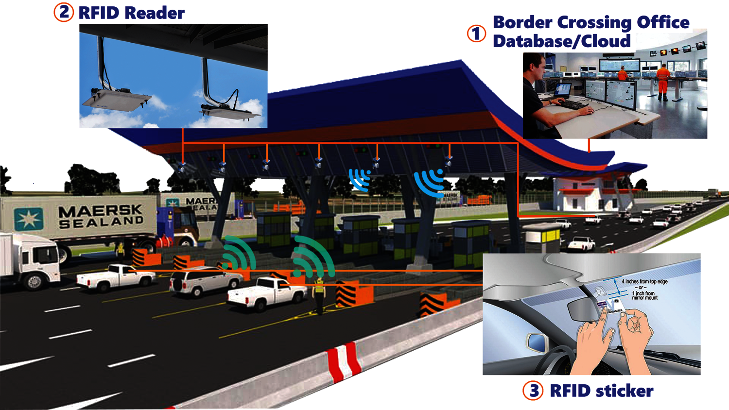
Figure 1: Smart border pass system
Numerous research articles propose RFID development to secure data used in access control, electronic toll collection, transportation payment, and livestock management, among other applications. The electronic toll collection system (ETC) is an early example of how RFID technology automated toll collection [2–4]. When passing through a toll gate, an rigid RFID card issued to a vehicle will be used as a toll card for collection. This system is limited to resolving issues with traffic flow; it does not address issues with identity security. Multiple articles have proposed solutions to RFID security concerns through the use of sophisticated protocols and encryption. That result eliminates the difficult-to-replicate problem of RFID identity theft [4–10]. These articles instill trust in RFID applications. Additionally, several articles endorse developing an RFID tag antenna for RFID and sensing applications [11–16]. However, the antennas in these articles are typically designed and constructed using traditional FR4 material. That is appropriate for rigid RFID cards but may not be appropriate for the RFID stickers presented in this research.
A vehicular border pass is distinct from other applications since the requirements to apply an RFID tag. The RFID tag used as a vehicular border pass should be a sticker that can be easily applied to a windscreen, side screen, hood, door, or other difficult-to-remove parts of a vehicle as shown in Fig. 1. Any damage to the installed location, such as a rupture or stripping, renders it corrupted and unusable. This RFID sticker tag must be flexible enough to paste or stick to various surfaces, bendable, resistant to extreme weather, and most importantly, inexpensive. Traditional copper-nickel and FR4-epoxy tags are ineffective in this situation due to the difficulty of bending and adhering to arched surfaces. Furthermore, it is still prohibitively expensive for RFID systems with a budget of 5 cents per tag [17].
In the last decade, graphene and related materials were presented for low-cost, flexible electronic applications. Graphene possesses many remarkable properties: high conductivity, mechanically robust, flexible, transparent, chemically stable, and low-cost [18,19]. Some models of antenna based on graphene were proposed for RFID applications [20–23]. Almost all graphene antenna models were designed and fabricated with graphene-ink on various substrates by the conductive/graphene-ink printer. Numerous companies have offered graphene sheets for flexible electronic applications in recent years. New graphene-sheet models have a conductivity of up to S/m. It is incredibly affordable, versatile, and simple to cut to fit the design. As a result, we believe it will meet the requirements for an RFID tag antenna used in conjunction with the vehicular smart border pass system. As a result, this research article proposes developing a graphene-based RFID sticker tag antenna. The research objectives are to (i) investigate and survey the development of RFID tag antennas for incorporation into vehicular smart border pass systems, and (ii) design, verify, and propose a graphene-sheet rectangular-shape microwave 2.4 GHz RFID sticker tag antenna for use in vehicular smart border pass systems.
RFID applications utilize four types of frequencies: low frequency (LF, 125–134 kHz), high frequency (HF, 13.56 MHz), ultra-high frequency (UHF, 860–960 MHz) and microwave frequency (2.4, 5.8, and 24 GHz). The purpose of this article is to design a graphene-based RFID tag antenna for the microwave frequency band, which offers a higher bandwidth and a smaller antenna size than the LF, HF, and UHF bands. Additionally, there is the possibility of manufacturing several microchips that comply with microwave RFID protocols that can be obtained for a few cents from various microelectronics companies shortly. As a result, this frequency is appropriate for the vehicular smart border pass system.
The rectangular-shape monopole design illustrated in Fig. 2 achieves the optimal trade-off between implantation ease and efficiency in developing a high-performance antenna. Based on the theory of microstrip antenna design [24] and previous research [25–31], the rectangular-shape monopole antenna model is used in this situation due to its simplicity of fabrication using standard tools and graphene sheets. The following is an empirical equation for any dimension in Fig. 2.
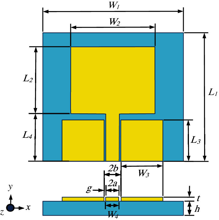
Figure 2: Rectangular-shape monopole antenna model
where
where
where
and
where
The length of the rectangular monopole antenna is calculated from the following equation.
where
while
and
where
An impedance of antenna is calculated from a following equations.
where
While
where
and
While
and
where
and
Almost all RFID tag integrated circuits have a 50 ohms input impedance with the RFID tag antenna designed for the tag. The gap dimension
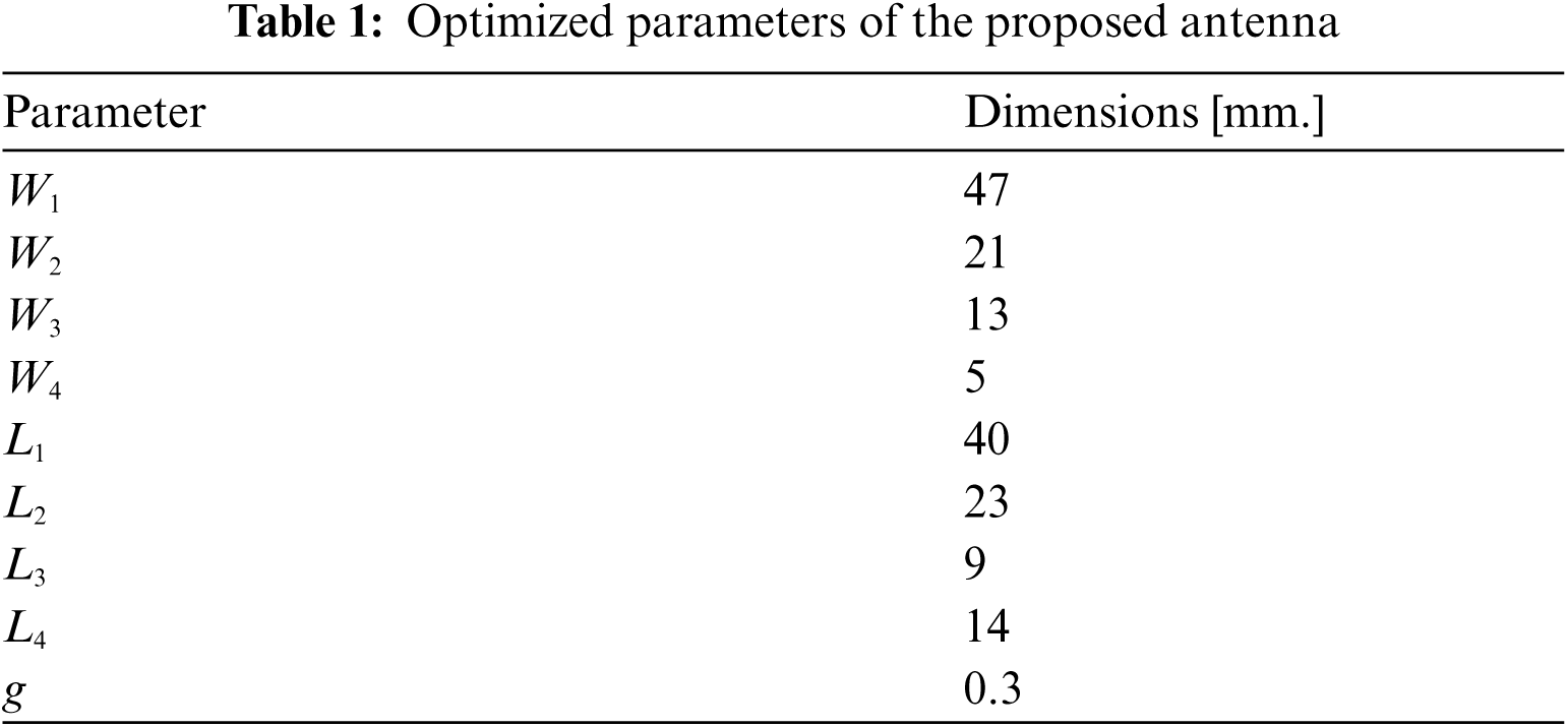
The CST software carries out the antenna performance pattern. The optimized dimensions of the proposed antenna in the microwave 2.4 GHz band are listed in Tab. 1. The graphene sheet used to build the antenna in this research has a polyimide substrate with a thickness
The simulated reflection coefficient, S11, of the microwave 2.4 GHz band designed antenna is shown in Fig. 3. At the same time, the simulated radiation pattern occurred in Fig. 4. The antenna presents a bandwidth of 850 MHz approximately, corresponding to a reflected power less than 10% around the center frequency of 2.4 GHz, which covers the frequency range from 2.14 to 2.99 GHz. The lower reflection coefficient is −31.564 dB, as shown in Fig. 3. As illustrated in Fig. 4a, the XZ plane's radiation pattern is omnidirectional. The co-polar plane receives the most radiation, while the cross-polar plane receives the least. In Fig. 4b, the radiation pattern in the YZ plane is bi-directional. Maximum radiation occurs between 0 and 180 degrees in the co-polar plane, while the lowest radiation occurs between 90 and 270 degrees. The designed antenna is angled opposite the source antenna to minimize the radiation pattern in the cross-polar plane. Fig. 5 illustrates the antenna's three-dimensional radiation pattern. The pattern of radiation is omnidirectional and has a maximum gain of 1.93 dBi. This characteristic monopole antenna radiation pattern demonstrates that the antenna radiates effectively in the far-field. These simulation results illustrate the optimal parameters for fabricating the graphene antenna in the following section.
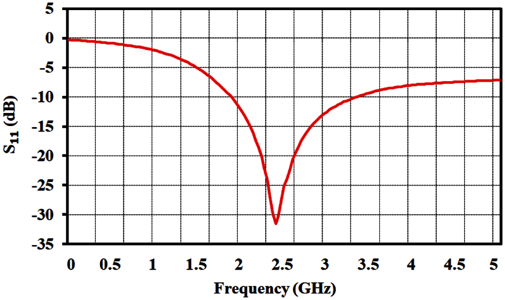
Figure 3: Simulated reflection coefficient S11 at 2.4 GHz band
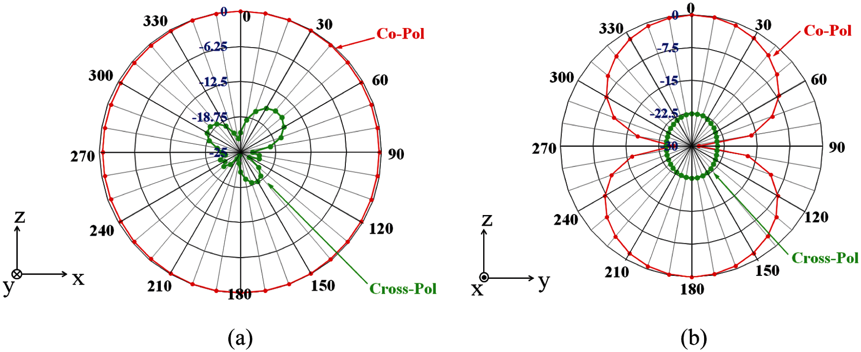
Figure 4: Simulated normalized gain radiation patterns at 2.4 GHz band (a) XZ-plane and (b) YZ-plane
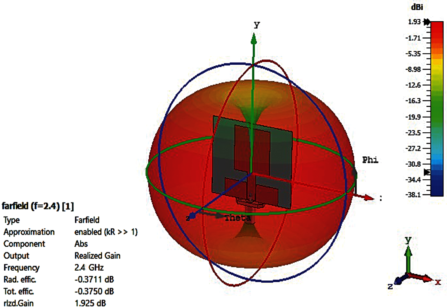
Figure 5: Antenna 3-dimension radiation pattern simulation result
4 Implementation and Measurement Results
To fabricate the designed graphene antenna, print the draft antenna on paper to the dimensions specified in Tab. 1. Then, adhere the draft paper to the graphene sheet that has been prepared. After that, cut the graphene sheet to the dimensions specified in the draft and remove any undesirable conductive material from the substrate. Finally, using silver conductive glue attaches the SMA connector to the graphene antenna. Fig. 6a illustrates the completed graphene antenna.
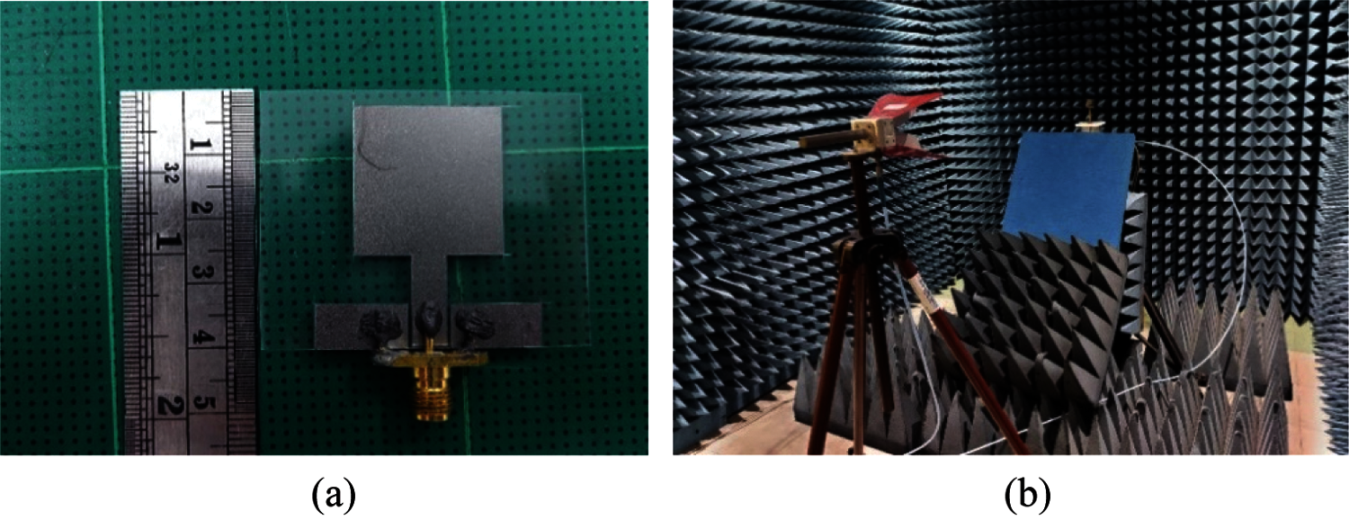
Figure 6: (a) Proposed graphene antenna (b) radiation pattern measurement setup
The proposed graphene antenna's reflection coefficient, radiation pattern, and gain are determined using a network analyzer. The measurements of the reflection coefficient are classified into two categories. In the first instance, the antenna has adhered to a rubber sheet in the laboratory. The second scenario is to attach the antenna to the windscreen of a car. The measurement results are as illustrated in Fig. 7. In the case rubber sheet, the antenna has a bandwidth of approximately 700 MHz and a reflected power of less than 10% around the center frequency of 2.4 GHz. It covers the frequency range of 2.2 to 2.9 GHz. The reflection coefficient S11 is approximately −42 dB. The antenna's input impedance was measured. It has a resistance of 49.783 + j0.55 ohms, which is close to the specification. The antenna has a bandwidth of approximately 900 MHz when mounted on a car windscreen, corresponding to a reflected power of less than 10% around the center frequency of 2.2 GHz, covering the frequency range of 1.8 to 2.7 GHz. The reflection coefficient S11 is approximately −24.8 dB. The measurements indicate that attracting graphene to a glass windscreen results in more minor frequency shifts. The bandwidth, however, is sufficient to cover the active spectrum used in microwave RFID applications. In addition, the measured reflection coefficient S11 has a slight ripple in both situations due to reflections in the interconnect caused by impedance discontinuities during the measurements.
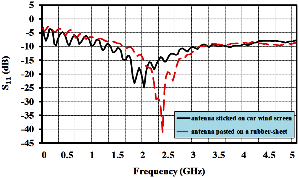
Figure 7: Measured results of proposed graphene antenna
Furthermore, the proposed antenna has been evaluated against a curved surface. The antenna adheres to rolled foam in three diameters: 3.5, 5, and 6 inches, as illustrated in Fig. 8. Fig. 9 illustrates the measured results. The results indicate that while curvature affects the reflection coefficient, it does not affect the bandwidth or center frequency. A highly bent antenna reduces the reflection coefficient while maintaining the same bandwidth and center frequency as a flat case.
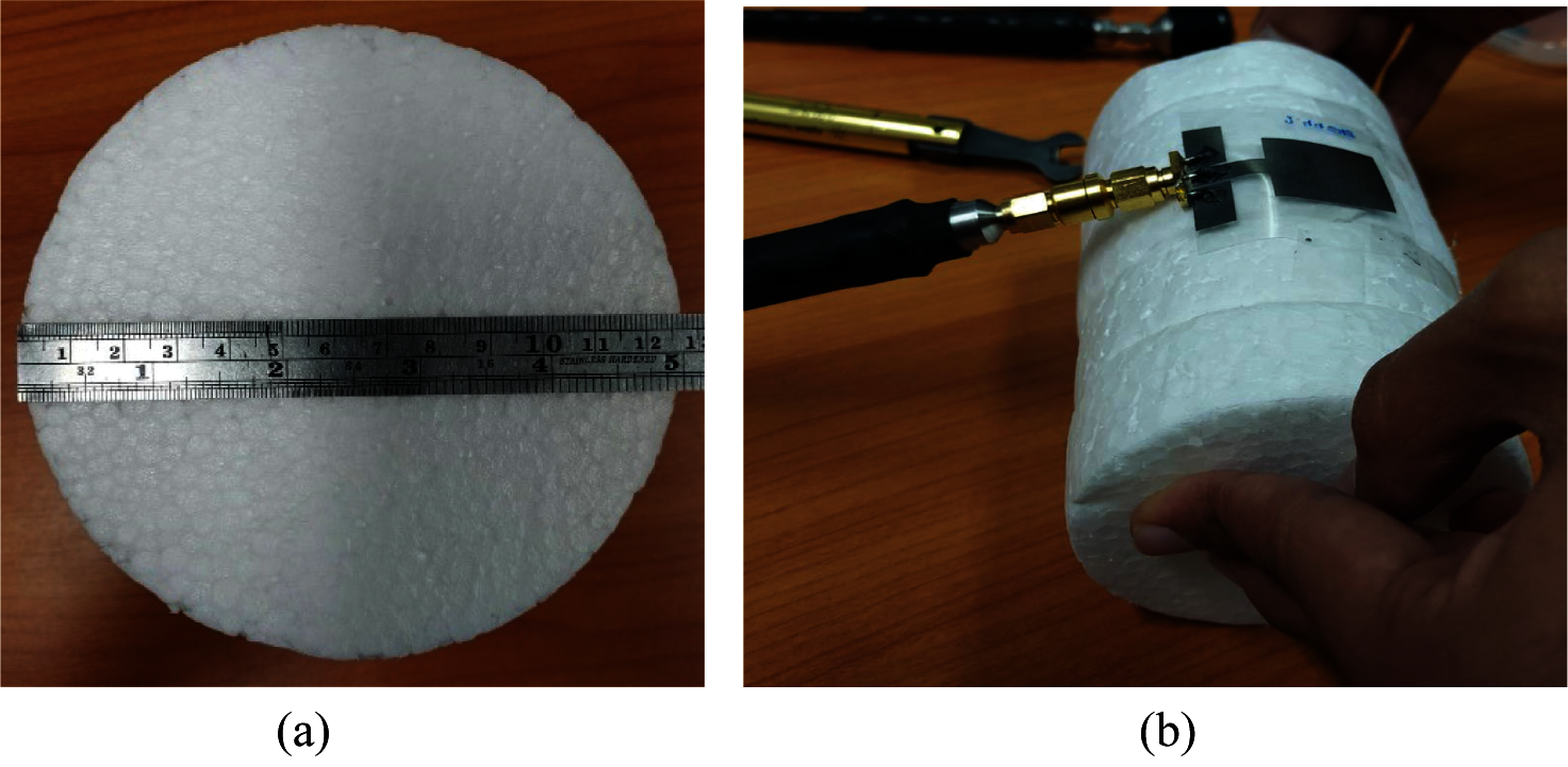
Figure 8: (a) Rolled foam dimension (b) attached antenna on rolled foam
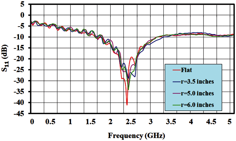
Figure 9: Measured S11 on curve surface
The radiation pattern and gain are measured in the manner represented in Fig. 6b, and the results are given in Fig. 10. The radiation in the XZ plane is shaped differently in Fig. 10a than in the simulation result. It does, however, retain its omnidirectional form. The co-polar plane receives the most radiation, while the cross-polar plane receives the least. In Fig. 10b, the radiation pattern in the YZ plane is bi-directional. It is shaped similarly to the simulation result in the co-polar plane. It has a wider shape in the cross-polar plane than the simulation result but is still far from the co-polar shape. The average radiation gain at the frequency to be used of the 2.4 GHz microwave RFID band is 1.23 dBi. All measured values are consistent with those obtained from simulations. As a result, it is possible to confirm that the proposed graphene antenna can be used with RFID stickers in a vehicular smart border pass system.
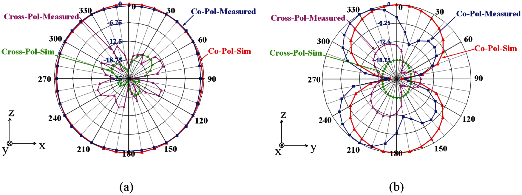
Figure 10: Measured radiation patterns at 2.4 GHz band (a) XZ plane and (b) YZ plane
The article proposes and designs a graphene-sheet rectangular-shape monopole microwave RFID antenna for vehicular smart border pass systems. The experiments are applied in the laboratory and on a car's windscreen to verify the proposed antenna's efficiency. The proposed antenna provides approximately 700 MHz bandwidth around the 2.4 GHz center frequency, covering the frequency range of 2.2 to 2.9 GHz in a laboratory case. Simultaneously, the car windscreen case provides approximately 900 MHz of bandwidth around the 2.2 GHz center frequency, spanning the frequency range 1.8 GHz to 2.7 GHz. The achievable bandwidth covers the entire 2.4 GHz microwave RFID band in its entirety. The radiation pattern is omnidirectional, with an average gain of 1.23 dBi at the frequency to be used of the 2.4 GHz microwave RFID band and an input impedance of 49.783 + j0.55. Due to its low cost, small size, and bendability, it is ideal for assembling various tag integrated circuits to serve as vehicular smart border passings.
Acknowledgement: The authors would like to express their gratitude to the Department of Electronics and Telecommunications, Faculty of Engineering, Rajamangala University of Technology Thanyaburi, Thailand, for providing equipment and funding for this research. Moreover, the authors gratefully acknowledge the hall effect measurement system, which supported this research work sponsored by the National Electronics and Computer Technology Center, Thailand. Additionally, the authors wish to thank anonymous reviewers for their insightful comments, which aided in developing this research article.
Funding Statement: The Rajamangala University of Technology Thanyaburi, Thailand, is funding this research.
Conflicts of Interest: The authors declare that they have no conflicts of interest to report regarding the present study.
1. Transconsults, KMUTT and 2T consulting and management, “Study of the potential assessment and the preparation in transportation infrastructure and service to support the ASEAN community,” in Office of Transport and Traffic Policy and Planning, Ministry of Transport, Bangkok, 2015. [Google Scholar]
2. Z. Tang, “The design of ETC system based on RFID and image identification,” in The Int. Conf. on Energy, Power and Electrical Engineering, Shenzhen, China, pp. 236–240, 2016. [Google Scholar]
3. A. Bhavke and S. Pai, “Smart weight based toll collection & vehicle dectection during collision using RFID,” in 2017 Int. Conf. on Microelectronic Devices, Circuits and Systems, Vellore, India, pp. 1–6, 2017. [Google Scholar]
4. P. Asavanarakul and A. Ruengwaree, “Design and implementation of security code for the identification and authentication process of electronic toll collection system,” RMUTI Journal Science and Technology, vol. 12, no. 3, pp. 138–149, 2019. [Google Scholar]
5. T. Dimitriou, “A lightweight RFID protocol to protect against traceability and cloning attacks,” in The Security and Privacy for Emerging Areas in Communications Networks, California, USA, pp. 59–66, 2005. [Google Scholar]
6. S. Kungpisadan and S. Metheekul, “A secure offline key generation with protection against key compromise,” in The 13th World Multimedia Conf. on Systemics, Cybernetics, and Informatics, Orlando, Florida, USA, pp. 63–67, 2009. [Google Scholar]
7. S. Mungmee and S. Sittichivapak, “Development efficiency of RFID system in frame ALOHA communication,” Ladkrabang Engineering Journal, vol. 26, no. 2, pp. 7–12, 2009. [Google Scholar]
8. L. Cheng, L. Shenwen, L. Yingbo, L. Na and W. Xuren, “A secure and lightweight authentication protocol for RFID,” in 2015 IEEE 5th Int. Conf. on Electronics Information and Emergency Communication, Beijing, China, pp. 317–320, 2015. [Google Scholar]
9. G. N. Khan and M. B. Moessner, “Secure authentication protocol for RFID systems,” in The 20th Int. Conf. on Computer Communications and Networks, Hawaii, USA, pp. 1–7, 2011. [Google Scholar]
10. P. Peng and Y. Zhao, “Anti-cloning and Secure RFID Mutual Authentication Protocols,” in The 4th IEEE Conf. on Broadband Network and Multimedia Technology, Shenzhen, China, pp. 379–384, 2011. [Google Scholar]
11. S. Bhaskar, S. Singhal and A. K. Singh, “Folded-slot active tag antenna for 5.8 GHz RFID applications,” Progress in Electromagnetics Research, vol. 82, pp. 89–97, 2018. [Google Scholar]
12. Y. Yu, J. Ni and Z. Xu, “Dual-band dipole antenna for 2.45 GHz and 5.8 GHz RFID tag applications,” International Journal of Wireless Communications and Mobile Computing, vol. 3, no. 1, pp. 1–6, 2015. [Google Scholar]
13. A. Ruengwaree, P. Thongbor and S. Boonming, “The tiered umbrella-shaped monopole antenna for RFID system applications with 867 MHz,” in The 2015 IEEE Int. Conf. on Antenna Measurements & Applications, Chiang Mai, Thailand, 2015. [Google Scholar]
14. N. O. Parchin, H. J. Basherlou, R. A. Abd-Alhameed and J. M. Noras, “Dual-band monopole antenna for RFID applications,” Future Internet, vol. 11, no. 2, pp. 1–10, 2019. [Google Scholar]
15. J. Liu, “Dua-band RFID tag antenna using coplanar inverted-/L structure,” in The 2010 IEEE Int. Conf. on RFID-Technology and Applications, Guangzhou, China, pp. 96–99, 2010. [Google Scholar]
16. Y. Shi, C. Fang, K. Qi and C. H. Liang, “A broadband design of UHF fractal RFID tag antenna,” Progress in Electromagnetics Research Letter, vol. 58, pp. 45–51, 2016. [Google Scholar]
17. S. Veronneau and J. Roy, “RFID benefits, costs, and possibilities: The economical analysis of RFID development in a cruise cooperation global service supply chain,” International Journal of Production Economics, vol. 122, no. 2, pp. 692–702, 2009. [Google Scholar]
18. A. C. Ferrari, F. Bonaccorso, V. Falko, K. S. Novoselov, S. Roche et al., “Science and technology roadmap for graphene, related two-dimensional crystals, and hybrid systems,” Nanoscale, vol. 7, no. 11, pp. 4598–4810, 2015. [Google Scholar]
19. A. E. Del Rio Castillo, V. Pellegrini, A. Ansaldo, F. Ricciardella, H. Sun et al., “High-yield production of 2D crystals by wet-jet milling,” Master Horizons, vol. 5, no. 5, pp. 890–904, 2018. [Google Scholar]
20. T. Leng, X. Huang, K. H. Chang, J. C. Chen, M. A. Abdalla et al., “Graphene nanoflakes printed flexible meandered-line dipole antenna on paper substrate for low-cost RFID and sensing applications,” IEEE Antennas and Wireless Propagation Letters, vol. 15, pp. 1565–1568, 2016. [Google Scholar]
21. P. Kopyt, B. Salski, M. Olszewska-Placha, D. Janczak, M. Sloma et al., “Graphene-based dipole antenna for a UHF RFID tag,” IEEE Transactions on Antennas and Propagation, vol. 64, no. 7, pp. 2862–2868, 2016. [Google Scholar]
22. N. Curreli, L. Schirru, L. Gagliani, E. Maniero, G. Montisci et al., “Graphene-based ultra-wideband printed bow-tie antenna for remote tracking,” in 13th European Conf. on Antennas and Propagation, Krakow, Poland, pp. 1–4, 2019. [Google Scholar]
23. K. Jaakkola, H. Sandberg, M. Lahti and V. Ermolov, “Near-field UHF RFID transponder with a screen-printed graphene antenna,” IEEE Tranactions on Components, Packaging and Manufacturing Technology, vol. 9, no. 4, pp. 616–623, 2019. [Google Scholar]
24. C. A. Balanis, “Microstrip antennas,” In Antenna Theory: Analysis and Design, 3rd ed. NY, USA: Wiley, ch. 14, pp. 811–882, 2005. [Google Scholar]
25. A. Ruengwaree, W. Naktong and A. Namsang, “A TE-shaped monopole antenna with semicircle etching technique on ground plane for UWB applications,” in 2013 Proc. of the Int. Symp. on Antennas & Propagation, Nanjing, China, pp. 95–98, 2013. [Google Scholar]
26. W. Naktong, S. Kronsing and A. Ruengwaree, “The bandwidth enhancement of rectangular slot antenna with H and T-shaped slot tuning for ultrawideband applications,” in 2014 11th Int. Conf. on Electrical Engineering/Electronics, Computer, Telecommunications and Information Technology, Nakhon Ratchasima, Thailand, pp. 1–4, 2014. [Google Scholar]
27. A. Ruengwaree, A. Innok, W. Naktong and P. Boonmaitree, “The bandwidth enhancement of rectangular slot antenna with L-shaped and double I-shaped stub tuning for WLAN/WiMAX applications,” in 2015 12th Int. Conf. on Electrical Engineering/Electronics, Computer, Telecommunications and Information Technology, Hua Hin, Thailand, pp. 1–4, 2015. [Google Scholar]
28. S. Chanramrd, W. Naktong, P. Thongbor, S. Sakulchat, A. Ruengwaree et al., “The structure tuning of plug-shaped monopole antenna for wireless communication applications,” in 2017 Int. Symp. on Antennas and Propagation, Phuket, Thailand, pp. 1–2, 2017. [Google Scholar]
29. W. Naktong, A. Ruengwaree and T. Pumpoung, “A study of tuning the CPW fed basic geometric monopole antenna for UWB applications,” Naresuan University Engineering Journal, vol. 15, no. 1, pp. 17–32, 2020. [Google Scholar]
30. W. Naktong and A. Ruengwaree, “Four-port rectangular monopole antenna for UWB-MIMO applications,” Progress in Electromagnetics Research B, vol. 87, pp. 19–38, 2020. [Google Scholar]
31. W. Naktong, A. Ruengwaree, N. Fhafhiem and P. Krachodnok, “Resonator rectenna design based on metamaterials for low-RF energy harvesting,” Computer, Materials & Continua, vol. 68, no. 2, pp. 1732–1750, 2021. [Google Scholar]
 | This work is licensed under a Creative Commons Attribution 4.0 International License, which permits unrestricted use, distribution, and reproduction in any medium, provided the original work is properly cited. |