DOI:10.32604/cmc.2022.024050
| Computers, Materials & Continua DOI:10.32604/cmc.2022.024050 | |
| Article |
Low-Cost Flexible Graphite Monopole Patch Antenna for Wireless Communication Applications
1Department of Electronics and Telecommunication Engineering, Faculty of Engineering, Rajamangala University of Technology Thanyaburi (RMUTT), Pathum Thani, 12110, Thailand
2Division of Physics, Faculty of Science and Technology, Rajamangala University of Technology Thanyaburi, (RMUTT), Pathum Thani, 12110, Thailand
3Department of Telecommunications Engineering, Faculty of Engineering and Architecture, Rajamangala University of Technology Isan, Nakhon Ratchasima, 30000, Thailand
*Corresponding Author: Amnoiy Ruengwaree. Email: amnoiy.r@en.rmutt.ac.th
Received: 01 October 2021; Accepted: 02 November 2021
Abstract: This research investigates a monopole patch antenna for Wi-Fi applications at 2.45 and 5.2 GHz, and WiMax at 3.5 GHz. A low-cost and flexible graphite sheet with good conductivity, base on graphite conductive powder and glue is used to create a radiator patch and ground plane. Instead of commercially available conductive inks or graphite sheets, we use our self-produced graphite liquid to create the graphite sheet because it is easy to produce and inexpensive. The antenna structure is formed using a low-cost and easy hand-screen printing approach that involved placing graphite liquid on a bendable polyester substrate. This research focuses on designing and developing a low-cost, thin, light, and flexible patch antenna for wireless communication and smart glass applications. The proposed antenna utilizes CST microwave software for simulations to improve the parameters before fabrication and measurement. The simulation and measurement results for the reflection coefficients at 2.45 GHz, 3.5 GHz, and 5.20 GHz are reliable and cover the required resonance frequencies, antennas gain are 1.91, 1.98, and 1.87 dB, respectively. Additionally, the radiation patterns of both results are omnidirectional. In the experiments, bending the proposed patch antenna along with the cylinder with the radii of 60, 40, and 25 mm yielded the same measurement results as the unbent patch antenna.
Keywords: Graphite liquid; monopole patch antenna; hand-screen printing; flexible; low-cost; wireless communication applications
Today, wireless communication is commonly used in people's everyday lives. Researchers have also been increasingly interested in studying and designing antennas to support wireless communication applications, such as dual-band antennas at 2.45 and 5.8 GHz for active radio frequency identification (RFID) tags. This antenna used a CPW-fed transparent AgHT-8 thin film that included silver coat polyester on a thin and lightweight polyethylene terephthalate substrate [1]. Compact monopole RFID reader antenna 2.45 GHz was designed as a planar loop monopole element. The antenna was fed by a microstrip line on a printed circuit board with FR-4 substrate for vehicle detection in parking lots [2]. A slim planar short monopole antenna was designed on an FR-4 substrate consisting of a mirrored C-shape with a narrow gap from the ground to support a dual-band WLAN at 2.4 and 5.5 GHz: for laptop and tablet applications [3]. Dual-band antenna was designed by etching a butterfly slot with CPW-fed for 2.4 and 5.8 GHz, and 4G mobile communications on a PVDF substrate for energy harvesting applications [4]. A wearable monopole antenna was designed with CPW-fed for 2.45 GHz using graphene and carbon nanotubes (CNTs) conductors on a flexible PDMS substrate for body application [5]. Antennas designed on substrates for different applications change according to the deployment of each work, for example, a split ring ultra-wideband transparent antenna with CPW-fed by transparent silver-coated thin films (AgHT-4) conductors on PET polymer substrate for applications on glass windows and panels of buildings [6]. A wearable dual-band dipole antenna for 2.45 and 5.8 GHz using a superconductive shield textile with two U-shaped slot etching overlays on different substrate layers that could be used for bending along a cylinder critical for body efficiency [7]. A wideband rectangular-shaped microstrip patch antenna was designed from a copper plate on an extruded polystyrene (XPS) substrate to support IMT, WLAN, Bluetooth, Mobile WiMax, and X-band downlink satellite communications [8]. An L-shaped and stair-shaped microstrip patch antenna with CPW-fed was designed with two conductive elements between pure copper and zelt with two additional substrates between polyester and jeans to support dual-band frequency, 2.45 and 5.8 GHz, on a garment that could be used for WiFi and WiMax applications [9]. A transparent U-shaped monopole antenna with a microstrip line used Indium Thin Oxide (ITO) conductive coating on a glass substrate to support the WLAN and Bluetooth base on smart glass applications [10]. A dual-band wearable textile antenna was fabricated using a rectangular copper plate on top and meander-line copper on the bottom of a denim substrate to function in industrial, scientific, and medical bands of 2.45 GHz and 5.8 GHz [11]. The C-shape, E-shape, and U-slot antennas were built using an etching approach on FR-4 printed circuit board substrate to support essential bandwidth frequency. The antenna was studied to compare different shapes for narrowband and wideband response at 2.45 GHz, with enhancing and decreasing the bandwidth at resonance frequency [12]. A MIMO antenna with two small monopole radiators and a U-shaped ground plane for 2.45 GHz WLAN was designed on an FR-4 substrate for wireless USB dongle applications [13]. An F-shape monopole base MIMO antenna was designed. The application of this antenna is the wireless system at 2.45, 5.2, and 5.8 GHz with two monopole antenna elements, each mirror over FR-4 substrate and a ground plane with a dumbbell shape [14]. The antenna structure was designed on a graphite sheet. One large conductive sheet was bent into various shapes on various substrates, such as a microstrip patch antenna made of graphite on a flexible polyimide (Kapton) substrate. An antenna with a radius of 18 mm could be bent into any shape for ISM 2.4 GHz. As a result, the resonant frequency fluctuated less than that of a typical flat antenna with SMD components [15]. A graphite antenna was designed on a CPW-fed UWB antenna with a graphite sheet on thin adhesive tape substrate for 3.1–10.6 GHz and a microstrip antenna with graphite sheet on C-Foam PF-4 foam substrate to support 5.8 GHz. These antennas could bend shape at radiuses of 8 and 30 mm, respectively, and keep excellent frequency response performance compared with a flat antenna [16]. A quad-element UWB-MIMO antenna was designed on orthogonal four monopole antenna elements with CPW-fed on FR-4 covering the surface of polystyrene block with a cylindrical hole graphite sheet to increase isolation and effective decoupling between antenna elements for 3–11 GHz [17].
Furthermore, conductive inks were printed on different substrate types, such as elliptical wideband quasi-dipole antenna and CPW antenna optimized for operating at 2–5 and 1–20 GHz, respectively. The graphite WBQD and graphene CPW were screen-printed on polyimide substrate using a DEK Horizon 03i, comparable with silver WBQD and silver CPW, which were screen-printed on PET film substrate using EKRA E2 semi-automatic screen. All graphene and silver antennas agreed that the former could be used for low-cost wearable RF wireless communication devices [18]. A small meander line dipole antenna was fabricated by Ultimaker open-source 3D printing machine. It used nano-particle conductive inks, which were printed onto a V-plane polymer substrate for RFID tags [19]. A meander line dipole antenna was designed by graphene conductive ink (Ink G-102E), a screen-printing technique on a paper substrate, and rolling compression to support RFID (984–1052 MHz) low-cost and sensing applications. A comparison of bending results found that both bending and unbending were still covered by impedance matching all ranges [20]. A millimeter-wave T-shape monopole antenna with CPW-fed was designed for 5G networks (26–40 GHz). For wearable applications, a Dimatix inkjet printer (DMP-2831) fabricated this antenna with silver nano-particle conductive ink and screen-printing on PET substrate [21]. An elliptical shape monopole antenna with CPW-fed was designed by an inkjet printer with screen-printed silver conductive ink over the PET-film substrate to support UWB (3.4–12 GHz) [22]. In these literature reviews, several antennas have been designed and fabricated to support a variety of purposes.
Screen-printing by conductive inks on the substrates is becoming widely popular. The antenna shape can be designed independently and printed on various substrate materials, which are flexible for application in various systems, such as screen-printing on PET and a paper substrate whose antennas could be bent. This antenna was used to support wearable applications [6,18,20–22]. Still, all conductive inks must be printed by specific printers with special unique properties suitable for printing on flat materials only. Moreover, the printers are quite expensive, resulting in a possible limitation for developing antenna work in a group of researchers with a limited budget.
This study had two objectives. The initial goal was to develop a graphite glue that is less expensive than commercial products and can be easily screen-printed by hand without the use of expensive instruments such as a specific printer while providing strong electrical conductivity and maintaining various antenna features. The second goal was to create an antenna with a lightweight, simple, low-cost, and flexible structure. The prototype antenna performed WiFi communication at 2.45 and 5.2 GHz, and WiMax 3.5 GHz for wireless communication and smart glass applications.
2 Low-Cost Flexible Graphite Sheet Materials for Antenna Structure
2.1 Self-produced Graphite Sheet
According to previous research, FR4 printed circuit boards are widely utilized to create low-cost antennas with various functional features. The antenna, however, has the disadvantage of being thick and difficult to bend. Therefore, it is not suited for installing on curved surfaces that require flexible antenna structure in bending, and even if some substrates could be bent, the cost remains too high. In addition, to produce a planar antenna, different conductive powders were produced and combined with a chemical liquid [23,24] to resemble printing ink. The silver conductive powder is the most common and readily accessible conductive powder with good electrical conductivity. Due to its high cost, the silver conductive powder is often used in high frequency or precision work and is mixed with chemical liquid to produce conductive printing ink to create conducting sheet. It is also used with high-priced special printers [18–21]. However, this methodology is complicated for many researchers to explore and apply.
One aim of this research was to study cheap and simple materials to easily fabricate antenna structures. Moreover, the experimental produced a new liquid material compound of graphite glue for creating low-cost graphite sheets to replace the expensive process (i.e., no expensive use of printers) for graphite sheets production to fabricate antenna structures. Additionally, graphite conductive liquids can replace the chemical fluid in combination with other expensive conductive powders, avoiding the need for costly printers. This work used graphite conductive powder with a particle size of less than 20 microns (Sigma-Aldrich, Graphite powder 282863). It was combined with glue (Elmer's brand Glue-All: Multipurpose liquid glue, extra strong) to create the desired stickiness and adhesive capabilities, resulting in the graphite powder merging into a homogeneous consistency. This reduced its resistance and increased the electrical conductivity. To begin combining the graphite powder with the glue, measurements were done using a mixing cup. The graphite powder was then added into the prepared glue, where it was observed that the mixture gradually became more viscous as the graphite powder was stirred into the glue. At this point, we could identify how to optimize the ratio of glue to graphite powder.
These graphite liquids were generated experimentally by mixing graphite powder with Glue-All in four different types (Compound I–IV), as illustrated in Fig. 1a, to determine the appropriate viscosity results for adhesion. The four different forms of graphite liquids were described in depth. Compound I was composed of 10 g of graphite powder, 20 g of glue, and 5 g of water. Compound II comprised 10 g of graphite powder, 5 g of glue, and 15 g of water. Compound III comprised 15 g of graphite powder, 5 g of glue, and 20 g of water. Compound IV comprised 13 g of graphite powder, 20 g of glue, and 6.5 g of water. Compounds I and IV included an acceptable ratio of graphite powder, glue, and water. Compounds II and III appeared to be an out-of-balance combination of graphite powder, glue, and water. The graphite powder and glue appeared to adhere to one another in a layer beneath while the water floated above.
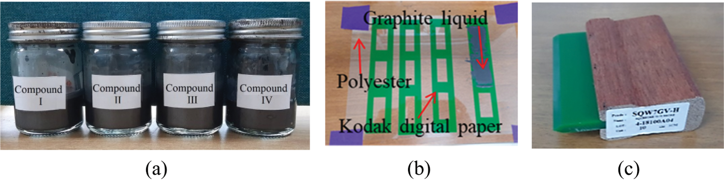
Figure 1: Materials and tools for creating graphite sheets (a) graphite liquids as Compound I–IV, (b) paper frame for hand-screen printing and a polyester substrate, and (c) screen printing squeegee
The experiment's physical tests of all four self-producing graphite liquids indicated that the Compound I and Compound IV's graphite liquids had appropriate viscosity. On the contrary, Compound II and Compound III's graphite liquids lacked sufficient viscosity. Following that, we used hand-screen printing to test the adherence of all graphite liquids to a substrate. Compound I–IV graphite liquids were hand-screen printed on a polyester substrate using a paper frame with a thickness of approximately 100 microns and an A4 paper dimension. A sticker paper with a thickness of 100 microns (Kodak digital paper) with pre-cut rectangular designs measuring 1.5 cm × 4 cm was utilized in that procedure, as illustrated in Fig. 1b. As illustrated in Fig. 1c, a screen-print squeegee (SQW7GV-H: 10 cm) was also utilized to assist in removing graphite glue smoothly.
In summary, it was noticed that graphite liquids containing Compound I and Compound IV printed smoothly and easily when compared to graphite liquids containing Compound II and III due to the viscosity difference between the liquids [19].
2.2 Graphite Sheets Properties
After completing the hand-screen printing of the graphite liquids on the polyester substrate, it took around six hours to dry the graphite sheets completely. Compound I graphite sheet was discovered to be smooth, adhesive, and flexible depending on the bending curve. The graphite sheet treated with Compound II was harder on the anterior surface and appeared to have creases, apparent stretch marks, and would not adhere to bending without cracking. Observation and testing revealed that the graphite sheet containing Compound III was comparable to the graphite sheet containing Compound II. Finally, the graphite sheet containing Compound IV exhibited excellent flexibility concerning relative elongation. Like the graphite sheet containing Compound I, it exhibited good bendability, as shown in Fig. 2a.
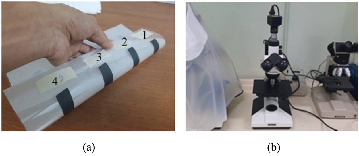
Figure 2: Physical test of graphite sheet: (a) bending test and (b) microscope for surface test
As shown in Fig. 2b, a microscope (Brand: SHODENSHA) was used to study all graphite sheet samples’ surfaces to determine the differences in the features of graphite sheets with the four compounds as Figs. 3a–3d. According to the investigation, graphite sheet treated with Compound I showed adequate adhesion to the material and a smooth, blending-friendly surface. Compound II and Compound III sheets lacked a sticky surface, and both sheets lacked a smooth, blending-friendly surface. Compound IV treated sheet adhered fully well to the substrate, and the surface was exceptionally smooth and ideal for blending [20].
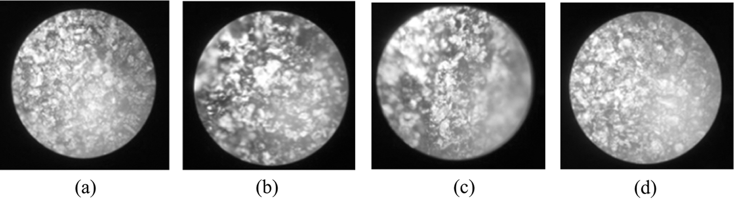
Figure 3: Observing the surface of all the graphite sheets: (a) Compound I,(b) Compound II, (c) Compound III, and (d) Compound IV
Compound I–IV graphite sheets were cut to approximately 1 × 1 cm for use with a Fluke Multi-meter for essential resistance measurement [25]. As shown in Fig. 4a, the resistance values were approximately 6800, 285, 165, and 130 ohms for Compound I–IV sheets, respectively. A thickness gauge was used to determine the thickness of dry graphite sheets on polyester (Brand: Mitutoyo). As illustrated in Fig. 4b, the average thickness of four identical measurements of dry graphite sheet on polyester was 80, 240, 240, and 200 microns for the four compound sheets, respectively, when the polyester thickness was 135 microns [25].
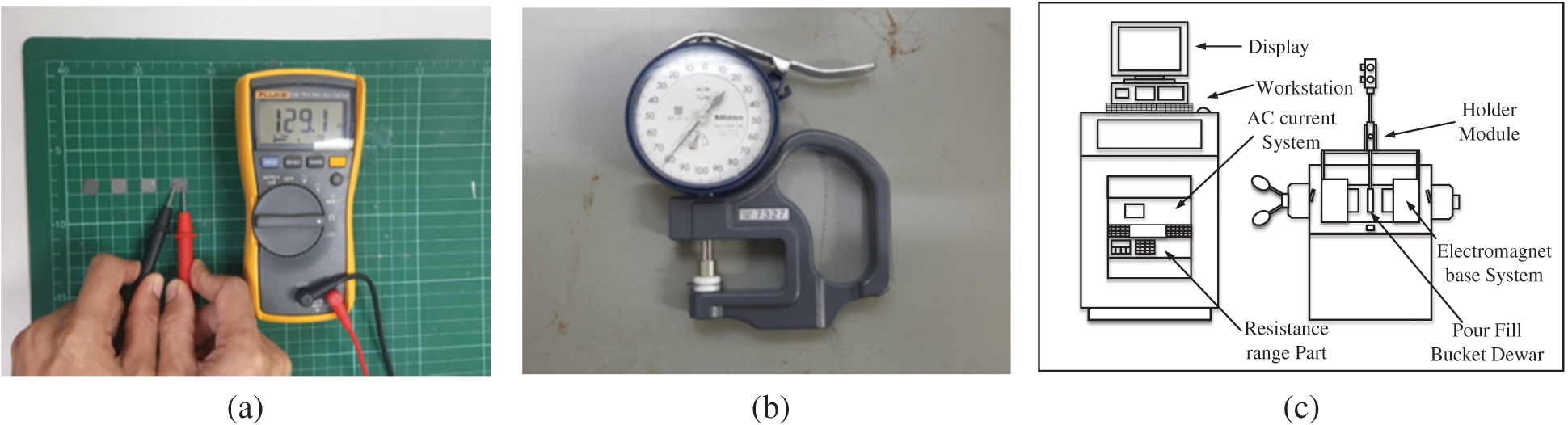
Figure 4: Impedance and conductivity measurement: (a) essential resistance, (b) thickness gauge, and (c) Hall effect measurement system
As illustrated in Fig. 4c, a Hall effect measurement system (LakeShore: EM4-HVA) was used to determine the resistance and conductivity of graphite sheets via a four-point probe for standard measurements [25]. Tab. 1 summarized the graphite sheet properties results of Compounds I–IV with the thickness obtained from the measurement of dry graphite sheets. Compound IV had the lowest resistivity, compared to the four graphite sheets at 1.14 ohm/cm, the lowest sheet resistance at 57.19 ohm/sq, and the best electrical conductivity at 8.74E−01 S/cm. Also, this research experimented by simulating the thickness of dry graphite sheets from the Hall effect measurement system software by adjusting different thicknesses between 60 and 240 μm, which is the range that can be screen printed by hand.

The generated simulation results of four graphite sheets by the Hall effect simulation program showed that the resistivity of all compounds slightly increased with an increase in the thickness except for the compound I sheet, as shown in Fig. 5a. However, all compound conductivity marginally decreased with increasing the thickness, as shown in Fig. 5b.
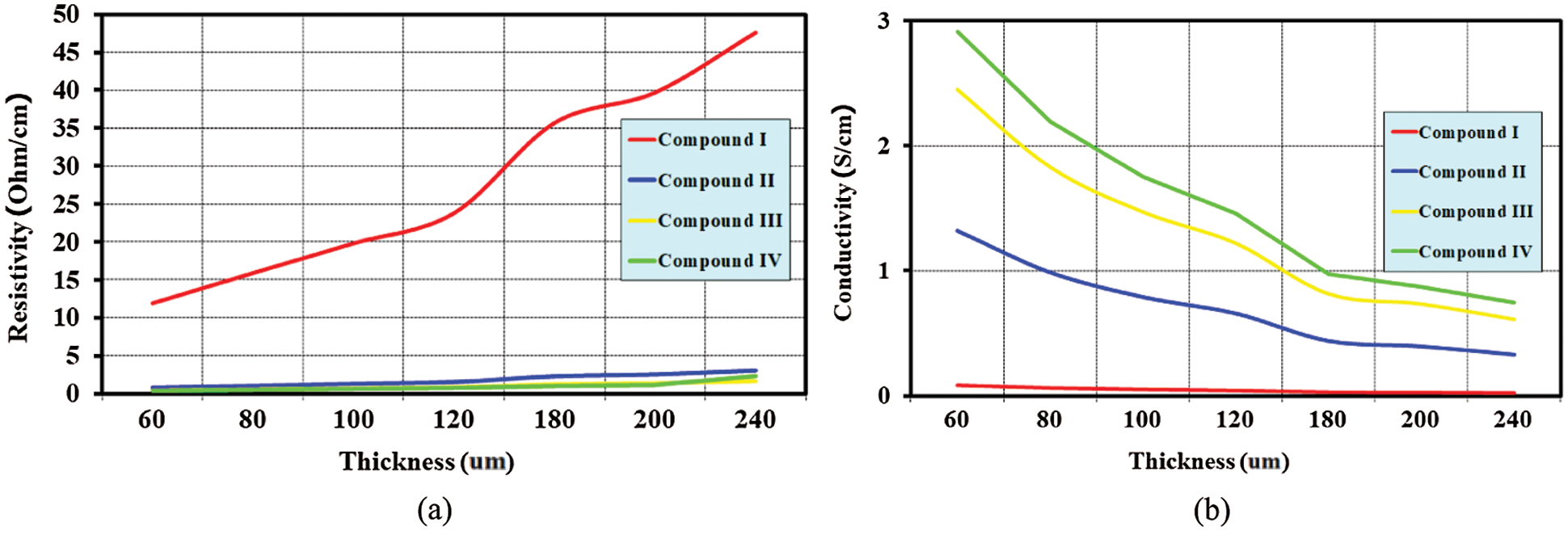
Figure 5: Properties of graphite sheets when adjusted with various thicknesses as generated by the Hall effect simulation software: (a) resistivity results and (b) conductivity results
Fig. 5b shows the generated simulation results of all graphite sheet thickness properties by the Hall effect simulation program. The various thicknesses adjustments from 60 to 240 μm showed an inverse proportion to the conductivity; when the thickness increased, the conductivity slightly decreased. On the contrary, when the thickness decreased, the conductivity slightly increased. However, this simulation result found that the average thickness was about 150 nm. The Compound IV sheet had the lowest average resistivity of all graphite sheets at the value of 9.26E−01 ohm/cm and the highest average conductivity at 1.56E + 00 S/cm. Therefore, the researcher attempted to use the Compound IV graphite sheet for a low-cost antenna design to support versatile wireless communication applications as the proposed target of this research.
Today, designing and developing antennas are more convenient and flexible due to specialized software that allows for the simulation and definition of antenna parameters based on the antenna's various essential structures.
Additionally, the results from commercial software are accurate and comparable to those obtained through measurement. This study chose the CST program for the antenna design process. The design process began with establishing the resonance frequency (fr) at 2.45 GHz. The basic dimensions of a simple rectangular monopole antenna structure [26–29] were determined using
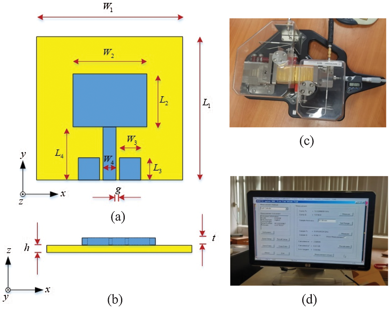
Figure 6: Antenna parameters: (a) a simple rectangular monopole antenna structure top view, (b) a simple rectangular monopole antenna structure bottom side view, (c) split cylinder resonator, and (d) split cylinder resonator monitor
A simple rectangular monopole antenna used graphite sheets from Compounds I–IV, which had an average conductivity of
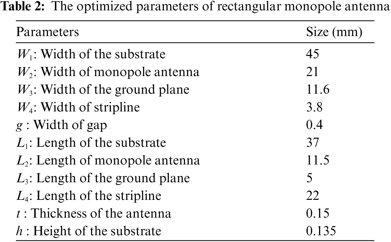
Fig. 7a. illustrates the reflection coefficients (
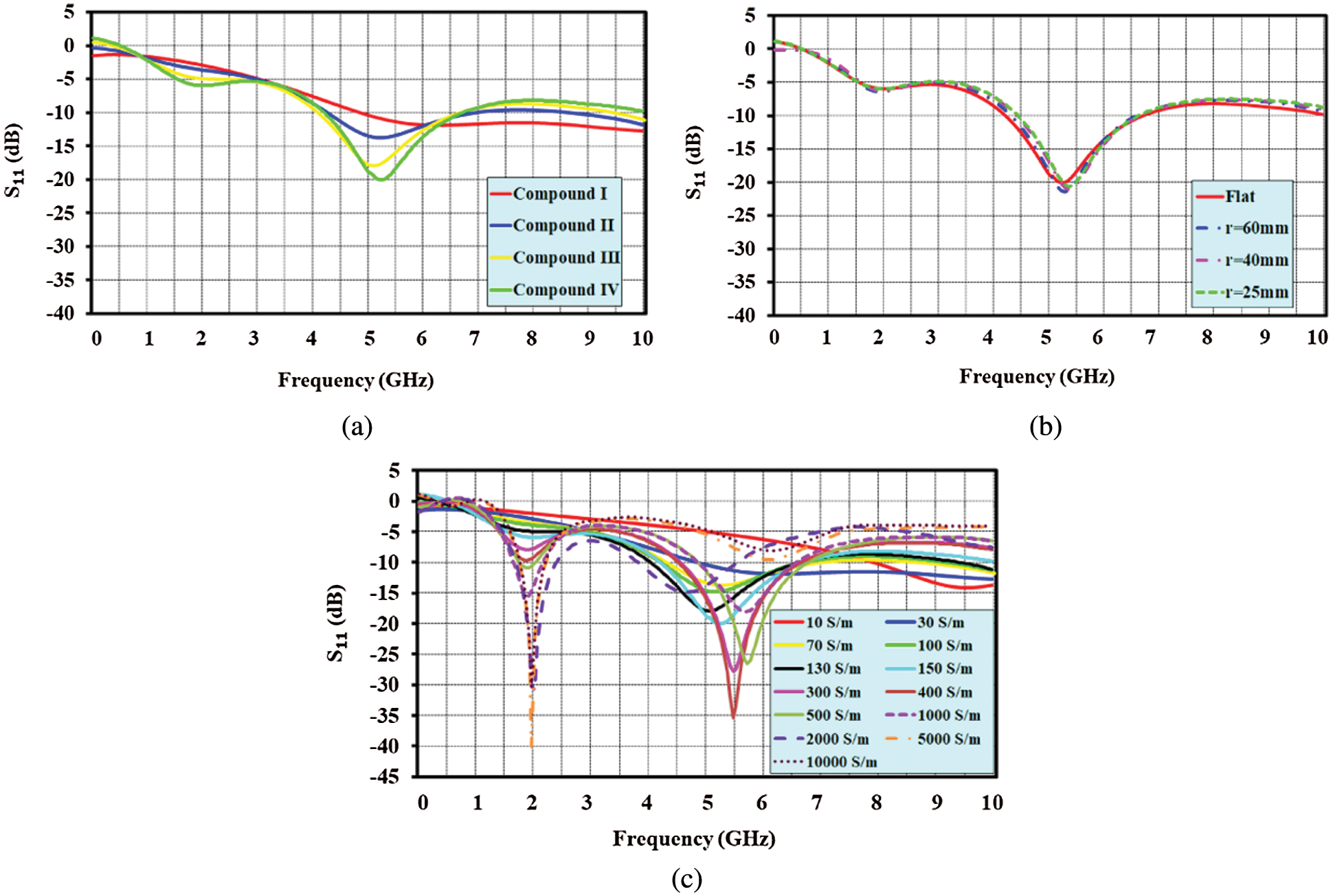
Figure 7: Simulation results: (a) reflection coefficient of compounds I–IV, (b) bending simulation result of Compound IV, and (c) adjustment of the conductivity between 10 S/m and 10,000 S/m
However, the bending of the graphite sheet antenna structure was critical for observing trends
Additionally, this research investigated adjusting the conductivity of the compounds between 10 and 10,000 S/m using CST software simulation to consider the reflection coefficient at the resonance frequency of 2.45 GHz from a simple rectangular monopole antenna structure, as illustrated in Fig. 7c. The conductivity simulation revealed that values less than 70 S/m would shift the resonance frequency from 2.45 GHz to higher frequency by approximately 2.5–3.8 times, which was unsuitable for this antenna design. Additionally, the conductivity range was between 70 and 1,000 S/m, with 1,000 S/m shifting the resonance frequency from 2.45 GHz to a higher frequency by around 2.1–2.4 times. Finally, if the conductivity was greater than 1,000 S/m, the frequency would approach 2.45 GHz, which can be optimized slightly using CST microwave software.
4 Fabrications and Measurements
In the first experiment, the four prototype graphite monopole antennas shown in Fig. 8a were fabricated and measured. The antenna's parameters are listed in Tab. 2. The radiator and ground plane formed a graphite sheet that was completed with liquid Compounds I–IV and adhered to a polyester substrate. The network analyzer Agilent E8363B was used to accomplish the measurements of all antennas. As a result of these issues, the resonance frequency of antenna compounds I–IV was shifted from 2.45 GHz to a high-frequency range of 7.56, 4.92, 4.67, and 5.29 GHz, as illustrated in Fig. 8b. The shifted frequency was due to the graphite sheet's conductivity being relatively low. Tab. 3 contains details about all measurement results, including bandwidth, resonance frequency, and reflection coefficient.
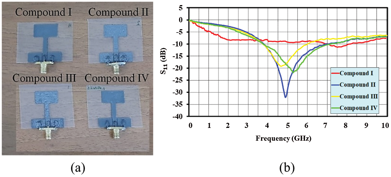
Figure 8: The fabricated and measured four prototypes of rectangular monopole antennas: (a) fabricated antenna structures and (b) reflection coefficient measurement results

According to the resonance frequency results in Tab. 3, the antenna with graphite sheet of Compound I shifted 3.08 times, Compound II shifted 2.01 times, Compound III shifted 1.91 times, and Compound IV shifted 2.16 times from its design frequency of 2.45 GHz. Referring to Section 2.2 and Tab. 1, Compounds I and IV exhibited considerable flexibility. Nonetheless, when compared to other compounds, Compound IV had the highest conductivity and the lowest resistance. A comparison of the simulation results in Fig. 7a and the measured results in Fig. 8b demonstrate that the resonance frequency did not shift. To prove that, additional three graphite sheet antennas with Compound IV were fabricated in the same dimension as those in Tab. 2 to observe the antenna parameter as shown in Fig. 9a. The antenna with Compound IV had a resonance frequency of 2.16 times the 2.45 GHz. Fig. 9b and Tab. 4 illustrate all actual antennas and their reflection coefficient results in comparison to others.
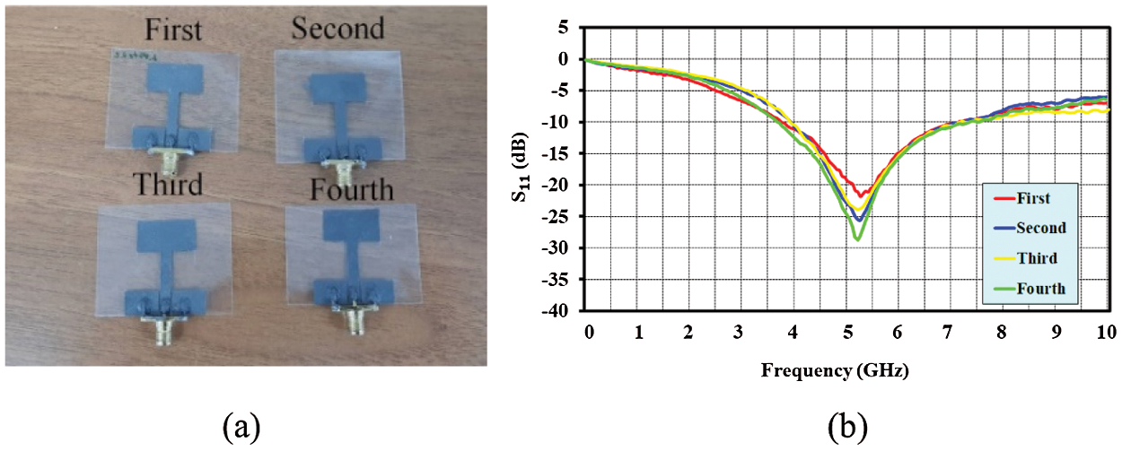
Figure 9: The fabricated and measured four prototypes of rectangular monopole antennas with compound IV: (a) the fabricated antenna structures and (b) the reflection coefficient measurement results

The comparison of the measured reflection coefficients results of four graphite sheet antennas with Compound IV is shown in Fig. 9b. As expected, all reflection coefficient values were similar for each antenna operating at approximately 5.2 GHz. The data in Tab. 4 demonstrate that the hand-screen printing process was simple and resulted in identical electrical characteristics for the four produced antennas. By substituting the following equation for Eq. (1), we can obtain a new tuned equation for the defined resonance frequency of graphite sheet with Compound IV:
where
Therefore, to tune the formula for the design process of the graphite sheet by Compound IV, the wavelength at the graphite sheet's resonance frequency (

4.2 Fabrication of Antennas with Tuned Equation
This section describes the fabrication of a prototype for a rectangular monopole antenna with graphite sheet Compound IV to support WiFi at 2.45 and 5.2 GHz, and WiMax at 3.5 GHz. The antenna was designed using a tuned equation. Then, using the CST software, the optimized parameters were obtained, as shown in Tab. 5. Fig. 10 illustrates the fabricated antenna with the three different frequency optimized parameters in Tab. 5, which were used to create the three different frequency prototype antennas. Agilent's E8363B network analyzer was used to obtain the measurement results. Fig. 11 and Tab. 6 show the comparison of the reflection coefficient, bandwidth, and resonance frequency between the simulation and measurement results. As a result, the outcomes were nearly identical for all WLAN and WiMax bandwidths. The radiation pattern was observed at 2.45, 3.5, and 5.2 GHz. There were omnidirectional in the XZ-plane and bidirectional in the YZ-plane, as shown in Fig. 12; the antenna gain was 1.91, 1.98, and 1.87 dB, respectively.
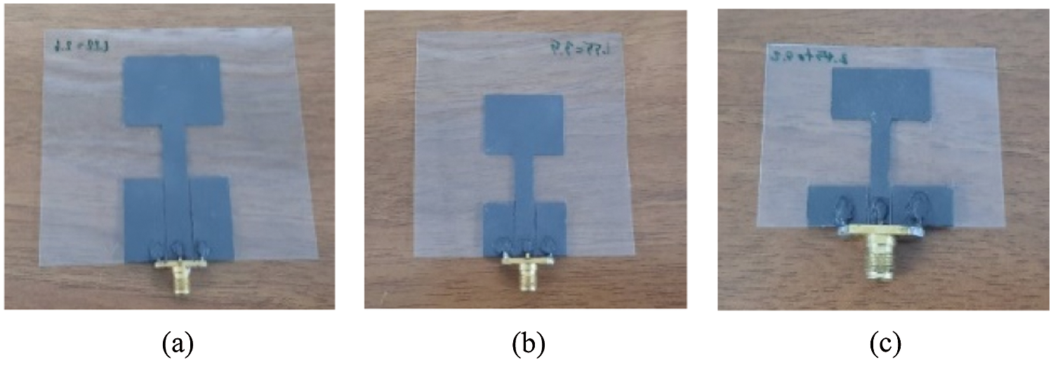
Figure 10: The fabricated three prototype antennas at (a) 2.45, (b) 3.5, and (c) 5.2 GHz
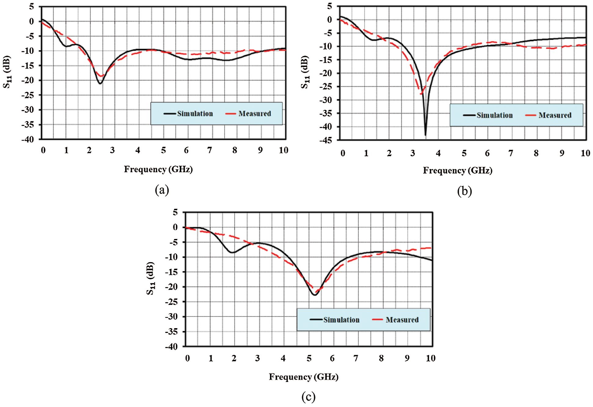
Figure 11: The comparison of simulation and measurement results of reflection coefficient at (a) 2.45, (b) 3.5, and (c) 5.2 GHz

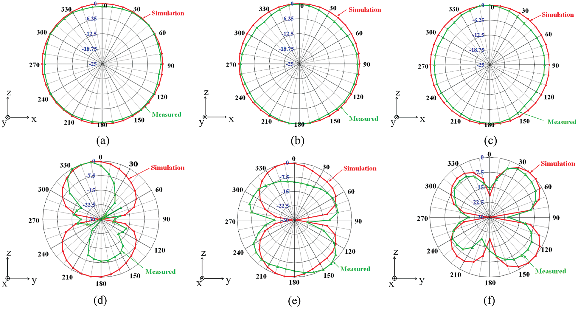
Figure 12: Simulation and measurement results of radiation pattern: (a) at 2.45 GHz in XZ-plane, (b) at 3.5 GHz in XZ-plane, (c) at 5.2 GHz in XZ-plane, (d) at 2.45 GHz in YZ-plane, (e) at 3.5 GHz in YZ-plane and (f) at 5.2 GHz in YZ-plane
The frequency response properties of the three proposed rectangular monopole antennas with graphite sheet Compound IV in the bent structure were investigated in this section at operating frequencies of 2.45, 3.5, and 5.2 GHz. In the first experiment, the samples were bent on a cylinder foam surface with radiuses ranging from 60 to 40 mm to 25 mm, as illustrated in Fig. 13a. The results were comparable to those of an antenna in a flat plane which slightly shifted upward but still covered the bandwidth frequency, as illustrated in Fig. 14 and Tab. 7.
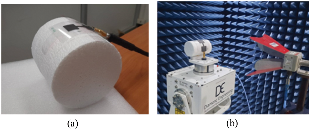
Figure 13: The experimentation of samples bent on a cylinder foam surface: (a) reflection coefficient measurement and (b) radiation pattern measurement
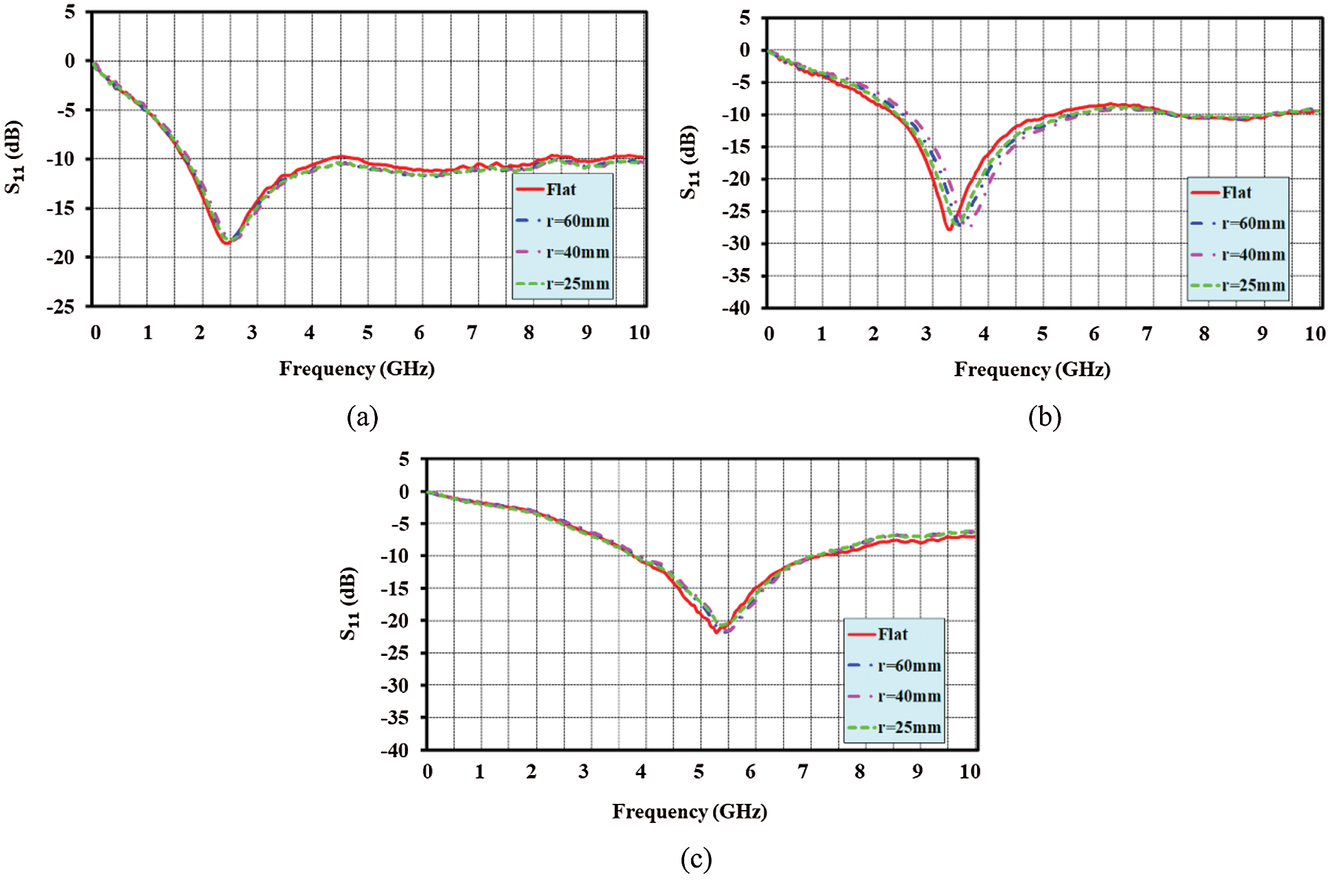
Figure 14: Measured reflection coefficient of bending graphite sheet Compound IV antennas with radius from 60, 40, to 25 mm at the operating frequency of at (a) 2.45, (b) 3.5, and (c) 5.2 GHz

When the antennas were bent on cylinder foam with a radius of less than 25 mm, the structure bending of these antennas was limited. That would imply that the feeding SMA connector would be removed from the antenna structure. Furthermore, when the bending curve of cylindrical foam is greater than 60 mm in radius, the antenna structure behaves like a flat plane antenna structure. As a result of the experiment, it was confirmed that these antennas could be used in various wearable wireless communication applications following the IEEE standard.
The radiation pattern of bent graphite sheet Compound IV antennas along cylinder foam surfaces with the radii of 60, 40, and 25 mm was measured in this section using an automation system in the chamber room, as illustrated in Fig. 13b. All bent curve structures and frequencies exhibited the same characteristics as the omnidirectional pattern, as illustrated in Fig. 15.
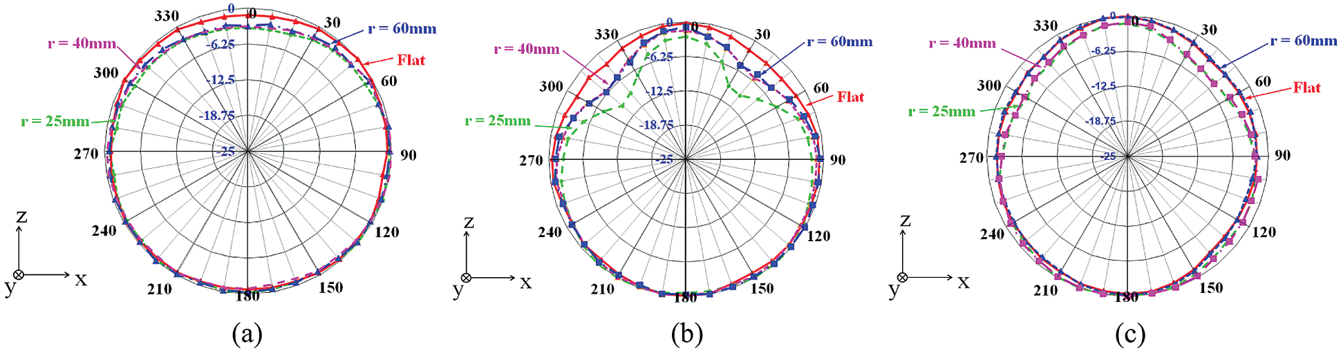
Figure 15: Measured results of the radiation pattern in XZ-plane when bent along the radius from 60, 40, to 25 mm on foam at (a) 2.45, (b) 3.5, and (c) 5.2 GHz
Following the evaluation of the antenna properties test, the two proposed bending graphite sheet Compound IV antennas operating at 2.45 and 5.2 GHz were used for WiFi application in conjunction with the WiFi 11AC USB adapter 2.4G/5.8G (AC1200). Then, as illustrated in Fig. 16 and Tab. 8, the efficiency was compared to the other commercial dual pole antennas operating at 2.45 and 5.2 GHz and the antenna inside a laptop. In Fig. 16, the receiving power of WiFi was measured using four different antenna configurations: inside the laptop, dual pole, proposed flat graphite sheet, and proposed bent graphite sheet. Tab. 8 was obtained using a laptop (Acer: Swift 3) running the Xirrus WiFi inspector program. The received power from the access point using four different physical antennas was identical at all operating frequencies of power between −56 to −48 dBm.
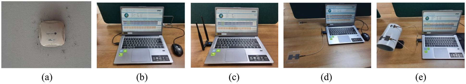
Figure 16: The prototype antenna testing: (a) access point, (b) antenna inside a laptop, (c) laptop with WiFi AC1200, (d) laptop with the proposed flat antennas, and (e) laptop with the proposed bent antennas

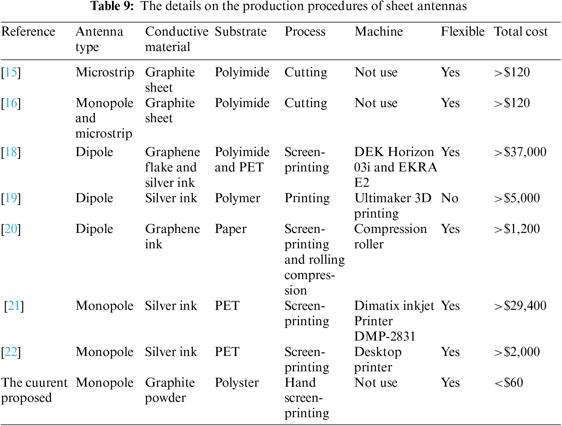
This research presents a low-cost, flexible planar mono antenna constructed of graphite sheet material that can be easily screen-printed while keeping the antenna's various features and low fabrication cost in comparison to earlier antennas. The cost covers the materials and machinery required to complete the primary process. The research [15] was designed with a graphite sheet from Panasonic on polyimide substrate that could bend into any shape. UWB microstrip antenna [16] was fabricated using a Panasonic graphite sheet adhered to a thin adhesive tape and a C-Foam PF-4 foam substrate. The dipole antennas [18] were created using a DEK Horizon 03i screen-printing graphene flake onto a polyimide substrate and an EKRA E2 screen-printing silver ink onto a PET film substrate, both of which were capable of bending. A dipole antenna [19] printed silver ink on a V-shaped plastic substrate that cannot bend using the open-source Ultimaker 3D printing machine. A printed dipole antenna [20] was created by screen-printing graphene conductive ink Ink G-102E on a paper substrate and then compressing it with SERP02 from Shining Energy LTD, Taiwan. A monopole antenna [21] was printed using a Dimatix inkjet printer with silver conductive ink on a bending PET substrate. An elliptical-shaped monopole antenna [22] was created using a low-cost desktop printer and screen-printed silver conductive ink over a bending PET film substrate. As shown in Tab. 9, the proposed antenna used graphite liquid made from graphite powder mixed with glue and hand-screen printing on a polyester substrate that could bend. This cost was calculated using the total cost of conductive materials and machines. An estimate was based on the conductive materials and machines sold on an online marketplace per paper unit in Tab. 9.
The new low-cost, flexible planar mono antenna prototype is fabricated by an easily hand-screen printing graphite liquid Compound IV onto a polyester substrate. By tuned equations
At resonance frequency of 2.44 (1.70–4.45 GHz), 3.41 (2.31–5.33 GHz), and 5.29 GHz (3.75–7.29 GHz), the proposed antenna exhibits a reflection coefficient of −18.55 dB with a gain of 1.91 dBi; −27.72 dB with a gain of 1.98 dBi; and −21.83 dB with a gain of 1.87 dBi. In terms of the radiation pattern, all antennas exhibit omnidirectional behavior. The antennas are then tested with a bent-on cylinder structure with 60, 40, and 25 mm radiuses. The test results show that a well-operating and no response effect still covers the desired application bandwidth frequency. Additionally, graphite conductive powder is considerably less expensive than silver conductive powder or commercial graphite sheet. This experiment enables conventional researchers to experiment and design antennas for smart glass and flexible wireless communication applications. We will focus on hand-screen printing onto various substrates in the future, including plastic bottles and rubber gloves, for low-cost wireless communication and sensing applications.
Acknowledgement: The authors would like to thank the Electronics and Telecommunications Engineering Department, Faculty of Engineering and Faculty of Science and Technology, Rajamangala University of Technology Thanyaburi for supporting us with the materials, equipment, and research funding. Moreover, the authors gratefully acknowledge the Hall Effect Measurement System, which supported this research work sponsored by the National Electronics and Computer Technology Center, Pathum Thani, Thailand.
Funding Statement: This work was supported by the RMUTT research and development fund.
Conflicts of Interest: The authors declare that they have no conflicts of interest to report regarding the present study.
1. M. A. Malek, S. Hakimi, S. K. Abdul Rahim and A. K. Evizal, “Dual-band CPW-fed transparent antenna for active RFID tags,” IEEE Antennas and Wireless Propagation Letters, vol. 14, pp. 919–922, 2015. [Google Scholar]
2. Y. He and M. Chen, “2.45 GHz broadband monopole RFID reader antenna buried in the ground of parking lot near the curb,” in 2016 IEEE Int. Conf. on RFID Technology and Applications (RFID-TA), Foshan, China, pp. 1–5, 2016. [Google Scholar]
3. J. Thakur and M. Tamrakar, “Dual band ultra slim WLAN antenna design for mobile devices,” in 2019 IEEE Asia-Pacific Microwave Conf. (APMC), Singapore, Singapore, pp. 1203–1205, 2019. [Google Scholar]
4. X. Bai, T. Ali and L. Xu, “A Dual-frequency slotted CPW antenna for 2.45/5.8 GHz RF energy harvesting based on PVDF,” in 2019 Int. Applied Computational Electromagnetics Society Symp.-China (ACES), Nanjing, China, 2019. [Google Scholar]
5. M. M. Mansor, S. K. A. Rahim and U. Hashim, “A CPW-fed 2.45 GHz wearable antenna using conductive nanomaterials for on-body applications,” in 2014 IEEE Region 10 Symp., Kuala Lumpur, Malaysia, pp. 240–243, 2014. [Google Scholar]
6. M. S. A. Rani, S. K. A. Rahim, M. R. Kamarudin, T. Peter, S. W. Cheung et al., “Electromagnetic behaviors of thin film CPW-fed CSRR loaded on UWB transparent antenna,” IEEE Antennas and Wireless Propagation Letters, vol. 13, pp. 1239–1242, 2014. [Google Scholar]
7. S. Yan, P. J. Soh and G. A. E. Vandenbosch, “Wearable dual-band magneto-electric dipole antenna for WBAN/WLAN applications,” IEEE Transactions on Antennas and Propagation, vol. 63, no. 9, pp. 4165–4169, 2015. [Google Scholar]
8. P. Kalra, A. Arora and E. Sidhu, “Novel microstrip patch antenna design employing extruded polystyrene (XPS) substrate for GSM, IMT, WLAN, bluetooth, WiMAX and X-band applications,” in 2016 Int. Conf. on Automatic Control and Dynamic Optimization Techniques (ICACDOT), Pune, India, pp. 775–778, 2016. [Google Scholar]
9. A. Mersani and L. Osman, “Design of dual-band textile antenna for 2.45/5.8-GHz wireless applications,” in 2016 5th Int. Conf. on Multimedia Computing and Systems (ICMCS), Marrakech, Morocco, 2016. [Google Scholar]
10. H. Raad, C. White, H. Schmitzer, D. Tierney, A. Issac et al., “A 2.45 GHz transparent antenna for wearable smart glasses,” in 2017 Progress in Electromagnetics Research Symp.-Fall (PIERS-FALL), Singapore, Singapore, pp. 99–102, 2017. [Google Scholar]
11. S. Li and J. Li, “Smart patch wearable antenna on jeans textile for body wireless communication,” in 2018 12th Int. Symp. on Antennas, Propagation and EM Theory (ISAPE), Hangzhou, China, 2018. [Google Scholar]
12. S. Bhardwaj and Y. Rahmat-Samii, “C-Shaped, E-shaped and U-slotted patch antennas: Size, bandwidth and cross-polarization characterizations,” in 2012 6th European Conf. on Antennas and Propagation (EUCAP), Prague, Czech, pp. 1674–1677, 2012. [Google Scholar]
13. W. Chen, C. Lin and H. Liu, “MIMO antennas with U-shaped ground and three protrued strips for WLAN applications,” in 2015 Int. Workshop on Antenna Technology (iWAT), Seoul, South Korea, pp. 156–159, 2015. [Google Scholar]
14. B. V. Singh, M. Agarwal and M. K. Meshram, “F-Shaped monopole based MIMO antenna for WLAN applications,” in 2016 IEEE Uttar Pradesh Section Int. Conf. on Electrical, Computer and Electronics Engineering (UPCON), Varanasi, India, pp. 576–579, 2016. [Google Scholar]
15. M. N. Yogeesh, K. N. Parrish and D. Akinwande, “Flexible graphite antennas for plastic electronics,” in 2014 IEEE 2nd Int. Conf. on Emerging Electronics (ICEE), Bengalore, India, 2014. [Google Scholar]
16. S. J. Chen and C. Fumeaux, “Highly efficient graphite antennas for conformal applications,” in 2018 Australian Microwave Symp. (AMS), Brisbane, QLD, Australia, pp. 61–62, 2018. [Google Scholar]
17. S. Wang, J. Hong, C. Wang and J. He, “A nonplanar quad-element UWB-MIMO antenna with graphite sheet to increase the isolation,” in 2018 IEEE MTT-S Int. Wireless Symp. (IWS), Chengdu, China, 2018. [Google Scholar]
18. A. Lamminen, K. Arapov, G. With, S. Haque, H. G. O. Sandberg et al., “Graphene-flakes printed wideband elliptical dipole antenna for low-cost wireless communications applications,” IEEE Antennas and Wireless Propagation Letters, vol. 16, pp. 1883–1886, 2017. [Google Scholar]
19. M. Ahmadloo and P. Mousavi, “A novel integrated dielectric-and-conductive ink 3D printing technique for fabrication of microwave devices,” in 2013 IEEE MTT-S Int. Microwave Symp. Digest (MTT), Seattle, WA, USA, 2013. [Google Scholar]
20. T. Leng, X. Huang, K. Chang, J. Chen, M. A. Abdalla et al., “Graphene nanoflakes printed flexible meandered-line dipole antenna on paper substrate for low-cost RFID and sensing applications,” IEEE Antennas and Wireless Propagation Letters, vol. 15, pp. 1565–1568, 2016. [Google Scholar]
21. S. F. Jilani, Q. H. Abbasi and A. Alomainy, “Inkjet-printed millimetre-wave PET-based flexible antenna for 5G wireless applications,” in 2018 IEEE MTT-S Int. Microwave Workshop Series on 5G Hardware and System Technologies (IMWS-5G), Dublin, Ireland, 2018. [Google Scholar]
22. D. C. Lane, A. T. Castro and S. K. Sharma, “Conductive inkjet printed ultra-wideband (UWB) planar monopole antenna on low cost flexible PET substrate material,” in 2015 IEEE Int. Symp. on Antennas and Propagation & USNC/URSI National Radio Science Meeting, Vancouver, BC, Canada, pp. 1958–1959, 2015. [Google Scholar]
23. A. S. M. Alqadami, N. Nguyen-Trong, B. Mohammed, A. E. Stancombe, M. Tobias et al., “Compact unidirectional conformal antenna based on flexible high-permittivity custom-made substrate for wearable wideband electromagnetic head imaging system,” IEEE Transactions on Antennas and Propagation, vol. 68, no. 1, pp. 183–194, 2020. [Google Scholar]
24. H. C. Bidsorkhi, A. G. D'Aloia, A. Tamburrano, G. D. Bellis and M. S. Sarto, “Waterproof graphene-PVDF wearable strain sensors for movement detection in smart gloves,” Multidisciplinary Digital Publishing Institute: Sensors, vol. 21, no. 16, 2021. [Google Scholar]
25. X. Huang, “Electromagnetic applications of graphene and graphene oxide,” Ph.D. dissertation, University of Manchester, UK, 2016. [Google Scholar]
26. P. Thongbor, “Development of dual rectangular monopole antenna with arrow-shaped slot etching and mutual coupling reduction for MIMO system applications,” M.S. thesis, Rajamangala University of Technology Thanyaburi, Thailand, 2016. [Google Scholar]
27. P. Thongbor, A. Ruengware, V. Pirajnanchai, W. Naktong and N. Fhafhiem, “Rectangular monopole antenna with arrow-shaped slot etching for UWB-MIMO application,” in 2016 13th Int. Conf. on Electrical Engineering/Electronics, Computer, Telecommunications and Information Technology (ECTI-CON), Chiang Mai, Thailand, 2016. [Google Scholar]
28. K. L. Prasanna1, B. R. Rao and P. V. Sridevi, “Design of CPW-fed monopole antenna with L-shape and T-shape for WLAN/Wi-MAX applications,” International Journal of Scientific & Engineering Research, vol. 5, issue 12, pp. 594–598, 2014. [Google Scholar]
29. C. A. Balanis, “ Antenna theory, analysis and design,” John Wiley & Sons, INC., 3rd ed., New Jersey, USA, 2005. [Google Scholar]
 | This work is licensed under a Creative Commons Attribution 4.0 International License, which permits unrestricted use, distribution, and reproduction in any medium, provided the original work is properly cited. |