DOI:10.32604/cmc.2022.023030
| Computers, Materials & Continua DOI:10.32604/cmc.2022.023030 | |
| Article |
Smart Anti-Pinch Window Simulation Using H-/H∞ Criterion and MOPSO
1Department of Electrical and Robotics Engineering, Shahrood University of Technology, Semnan, Iran
2Future Technology Research Center, College of Future, National Yunlin University of Science and Technology 123 University Road, Section 3, Douliou, Yunlin, 64002, Taiwan
3Faculty of Information Science and Technology, Universiti Kebangsan Malaysia, 43600, UKM Bangi, Selangor, Malaysia
*Corresponding Author: Shahab S. Band. Email: shamshirbands@yuntech.edu.tw
Received: 26 August 2021; Accepted: 10 November 2021
Abstract: Automobile power windows are mechanisms that can be opened and shut with the press of a button. Although these windows can comfort the effort of occupancy to move the window, failure to recognize the person's body part at the right time will result in damage and in some cases, loss of that part. An anti-pinch mechanism is an excellent choice to solve this problem, which detects the obstacle in the glass path immediately and moves it down. In this paper, an optimal solution
Keywords: H-/H∞; anti-pinch; residual; fault detection; multi-objective particle swarm optimization (MOPSO); multi-objective optimization; automotive; power windows; electric windows
The increasing growth of automated systems and their application in larger and more complex systems, and consequently the increased demand for safety systems, has led to a greater tendency towards fault detection techniques, particularly, model-based methods in dynamic systems. Failure to recognize in due time will result in damage and loss of a significant part of the capabilities and information and human resources in some cases. Due to the damage caused by the fault, the industries were interested in seeking a way to minimize the incidence of faults. It is impossible to prevent a fault in control systems. However, if the fault can be detected in a timely fashion and identified dynamically, then by applying a proper control rule, the amount of damage can be reduced to an acceptable level. Systems that have such capabilities are called fault-tolerant control systems. In these systems, some performance drop is also acceptable in the event of a fault [1,2].
There are two main approaches to fault detection: model-based fault diagnosis and non-model fault diagnosis [3]. The non-model fault diagnosis does not require a dynamic model of the system to detect a fault [4]. An analytical model-based diagnostic method is one of the most important methods for fault detection [5]. The model-based methods are generally faster and more accurate than the non-model approach. These methods use the idea of producing the residual signal, which results from a mismatch between the estimated behavior and the real system [6]. There are various methods for generating the residual signal, which are based on the observer-based approach, parity equations approach, and parameter estimation approach [7].
In the automotive industry, electronic systems, as they provide the customer's comfort, encounter vehicles with new needs [8]. One of these needs is the use of an automatic power window, which requires the finger to be pressed on the command button to move the window until the end of its course.
Due to non-compliance with safety issues, there have been several incidents involving work with power windows. Therefore, failure to correctly detect the fault will damage the part of the body in the window movement path [2,9]. As a result, the anti-pinch window control system has been very much taken into consideration.
In general, common methods for detecting pinch conditions are divided into two batches. In the first method, the Pinch estimator assumes that the window velocity is significantly reduced and the motion is steady. In this type of estimation, the required value of calculations is low, but its performance decreases in the presence of noise.
Another type that detects the pinch condition is when the motor torque exceeds a predetermined value, requiring an additional current sensor to prevent false alarms [10–12].
Definition: For the system given as
If the number of rows
If the number of rows
To calculate this criterion, we introduce the following Lemma.
Lemma: Assume that A, B, P, S, R are matrices with suitable dimensions; while P and R are symmetric, R> 0 and (A, B) are stable. Suppose two assumptions are satisfied [16]:
1. A does not have an eigenvalue on the imaginary axis.
2. P is defined as a positive semi-definite or negative semi-definite, while for (A, P), there is no observable mode on the imaginary axis.
Then X is a unique real symmetric response for the following equation [17]:
where,
In this research, an optimal algorithm is considered using the
In most cars, lifting the window is done using a very precise lever that keeps it leveling up. A small electric motor is connected to a spiral gear and several circular gears to produce sufficient lifting force to lift the window.
One of the important features of the power windows is that they cannot be opened by pressing; the helical gear prevents it. Most spiral gears are locked automatically due to the angle of contact between the helical gear and the round gear teeth. The helical gear can rotate the round gear, but the rounded gear cannot rotate the helical gear. The friction between the teeth makes the gears lock. The lever has a long arm attached to the bar that holds the bottom of the window. When the window rises, the end of the arm slips into the slot on the bar. On the other hand, there is a large plate at the end of the rod, where the gear teeth fall into it. The motor rotates the gear engaged with these teeth.
New generation cars are equipped with power windows that reduce the passenger's quest for moving car windows [18]. If the object is placed in the window path, for example, the child's hand, the window must stop at the moment. One method that automakers use to control the power of the window is the design of a circuit that measures the torque of the lift motor. If the motor torque decreases, the circuit will invert the inlet to the motor, and thus the window will return to the bottom. But the problem here is how long a fault is detected [19]. In fact, less time is desirable for our problem since less damage occurs to the obstacle. The overall view of the power window is shown in Fig. 1.
We consider the linear time-invariant system as following [14]:
where x is the state vector, u input control, y is the measurement vector, n is white noise, v is the disturbance, and f is the fault vector input.
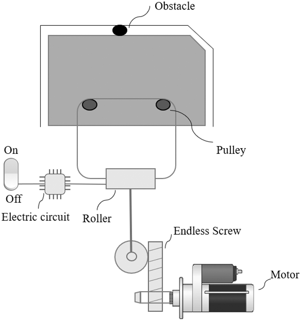
Figure 1: The overall view of the power window
The residual generator is considered as follows [14]:
where L,
Which shows that the dynamics of the residual signal r depends on the state e in addition to the parameters f, v and n. Another form of residual in Eq. (8) is as follows [14]:
where
2.1 Analytical Model of the Fault Detection Algorithm
The angular velocity
where b, J,
The matrices
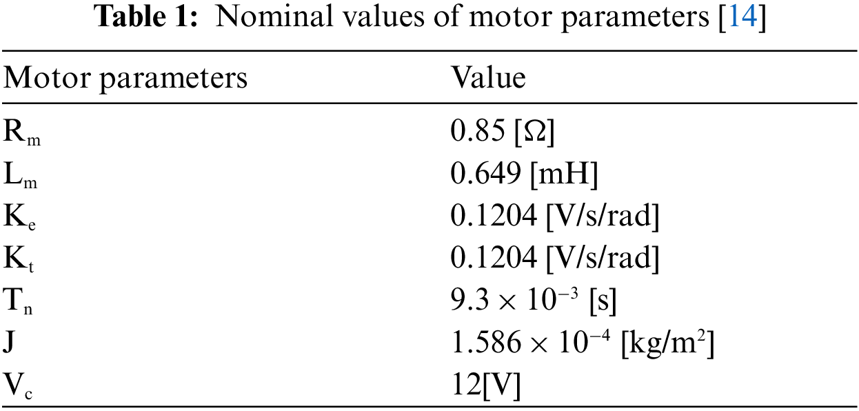
The DC motor parameters are obtained by experiments. The values of these parameters are shown in the Tab. 1.
By placing the above table data in the matrices A, B,
According to Eq. (6), to detect the fault, we select the matrices
3 Simulation of the System by Solving the MOPSO Algorithm
We want to transform the problem of controller design into an optimization problem and then solve the problem using the MOPSO algorithm [20]. We design the system in a way that can withstand any kind of uncertainty. We consider the linear state equation as [17]:
where
And, the measurement equation is:
where
The goal is to put the system in a proper position by applying a u so that z meet zero [21,22].
According to the Eqs. (12)–(14) we have:
The transfer function model is as [23]:
And, the closed-loop transfer function for input w and output z is:
Since,
The design goal in our chosen system is to reduce the angular velocity rate of the motor
Therefore, Eqs. (12)–(14) are rewritten as:
In the Eq. (18),
Figure 2: Anti-pinch window simulation toolbox
The impulse signal is v with a delay of 0 s, a domain of 50, and a width of 0.3 s. In addition, white noise is simulated with 0.00014, and its sampling frequency is 0.01.
The delay of impulse signal f is 2.7 s, with the amplitude of 1, and the width of 1 s. Now, we obtain a lookup using the MOPSO algorithm in MATLAB software.
In this section, we face a multi-objective optimization problem. The goal of problem-solving is to reduce the disturbance effect and increase the fault effect, meaning that we have to define two objective functions and simultaneously optimize their value [24,25]. Therefore, we use the MOPSO algorithm and define the cost functions according to the criterion
where
Fig. 3 shows the response of the MOPSO algorithm, which is represented by o and *, where * are members of the archive. The horizontal and vertical graphs represent the
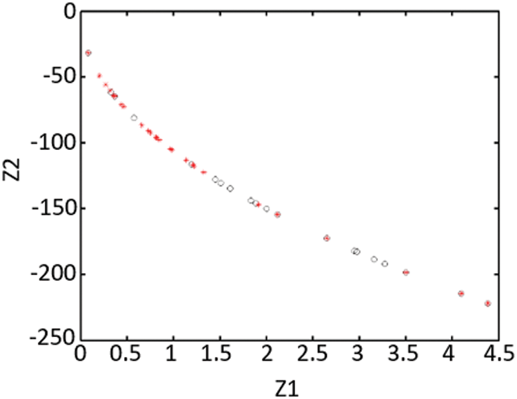
Figure 3: The cost functions of the mopso algorithm in the
As shown in Fig. 4, the sensitivity to the disturbance is well-faded and
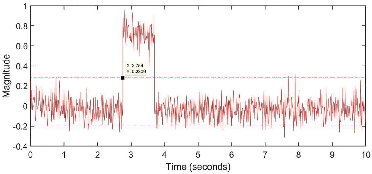
Figure 4: The residual signal in the
4.1 Closed-Loop System Analysis with L Controller and
In control systems, in order to formulate the controller design problem meeting the required characteristics, we use weighting functions [26]. In this section, we use the
To achieve the optimal level of disturbance reduction, it is necessary to establish a relation between S (the closed-loop system sensitivity function) and
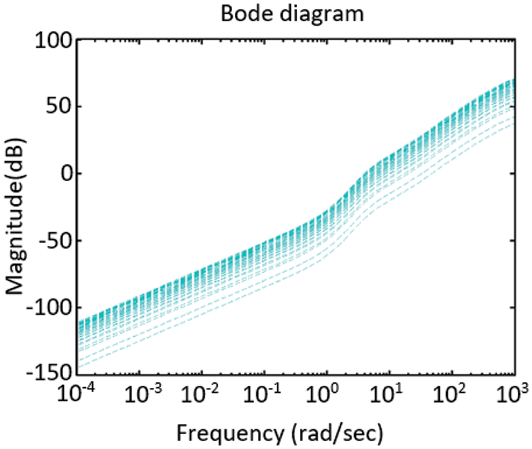
Figure 5: Bode diagram of an additive fault
We assume that for all types of frequency:
To reach this condition, we can say if and only if
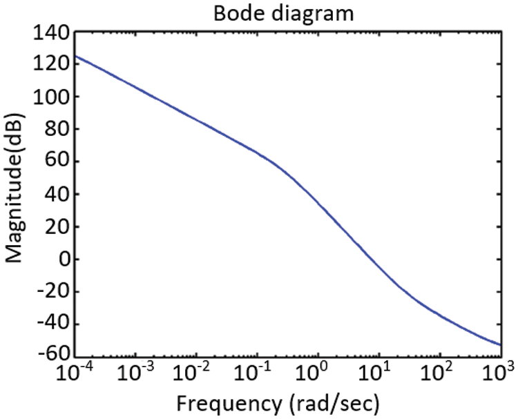
Figure 6: Exceptional values
The result of the comparison between the sensitivity function and the inverse weighting function is shown in Fig. 7. As can be seen, the sensitivity function is located below the
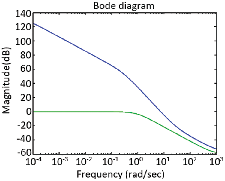
Figure 7: The inverse of the weighted function (blue line) and the sensitivity function using the
4.2 Comparison of System Simulation Results with MOPSO and LMI Algorithms
Using the LMI algorithm, the observer's gain for this system is obtained from [14]:
Fig. 8 shows the residual signal in the LMI and MOPSO methods using the
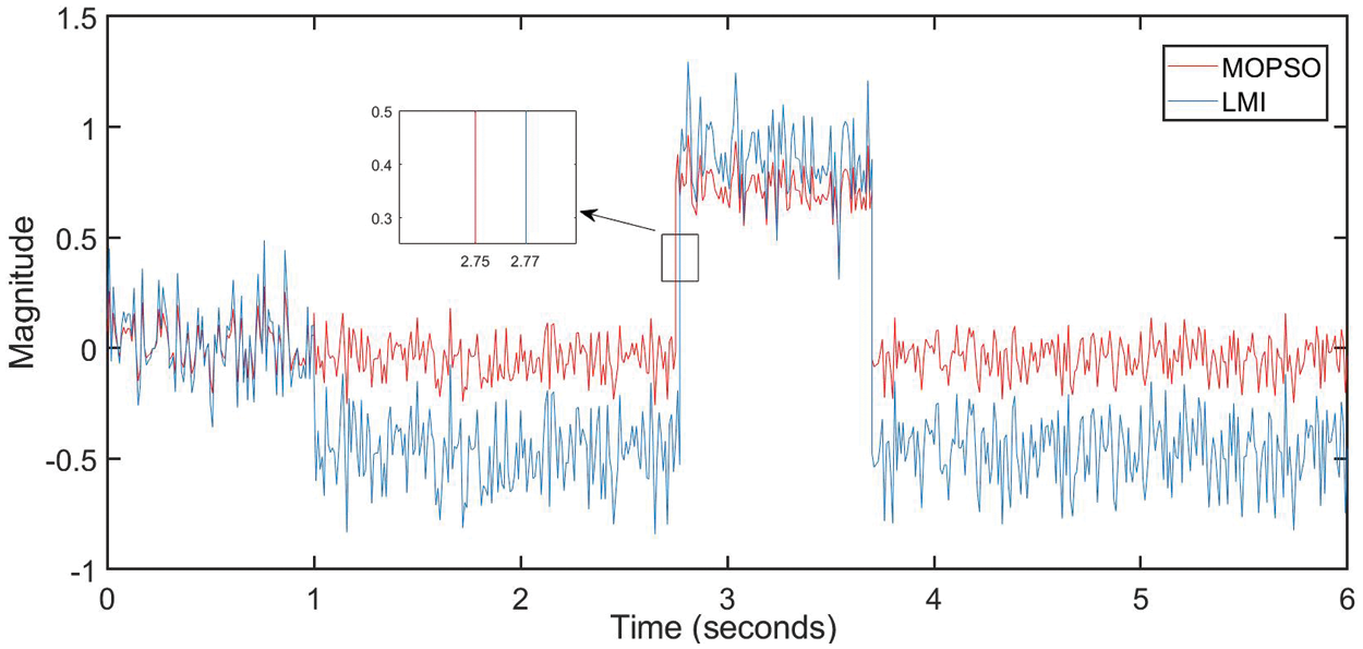
Figure 8: The residual signal comparison in the mopso and lmi method using the
In this paper, the design of the
Funding Statement: This research was supported by DP-FTSM-2021, Dana Lonjakan Penerbitan FTSM, UKM.
Conflicts of Interest: The authors declare that they have no conflicts of interest to report regarding the present study.
Reference
1. I. Hwang, S. Kim, Y. Kim and C. E. Seah, “A survey of fault detection, isolation, and reconfiguration methods,” IEEE Transactions on Control Systems Technology, vol. 18, no. 3, pp. 636–653, May 2010. [Google Scholar]
2. X. He, Z. Wang, Y. Liu, L. Qin and D. Zhou, “Fault-tolerant control for an internet-based three-tank system: Accommodation to sensor bias faults,” IEEE Transactions on Industrial Electronics, vol. 64, no. 3, pp. 2266–2275, Mar. 2017. [Google Scholar]
3. I. Samy, I. Postlethwaite and D. -W. Gu, “Survey and application of sensor fault detection and isolation schemes,” Control Engineering Practice, vol. 19, no. 7, pp. 658–674, Jul. 2011. [Google Scholar]
4. J. Ma and J. Jiang, “Applications of fault detection and diagnosis methods in nuclear power plants: A review,” Progress in Nuclear Energy-PROG NUCL ENERGY, vol. 53, pp. 255–266, Apr. 2011. [Google Scholar]
5. A. Mojallal and S. Lotfifard, “Multi-physics graphical model-based fault detection and isolation in wind turbines,” IEEE Transactions on Smart Grid, vol. 9, no. 6, pp. 5599–5612, Nov. 2018. [Google Scholar]
6. E. Sobhani-Tehrani and K. Khorasani, Fault Diagnosis of Nonlinear Systems Using a Hybrid Approach, vol. 383, Springer Science & Business Media, pp. 21–49, 2009. [Google Scholar]
7. R. Isermann, “Model-based fault-detection and diagnosis–status and applications,” Annual Reviews in Control, vol. 29, no. 1, pp. 71–85, Jan. 2005. [Google Scholar]
8. J. Kunkel, “Anti-pinch window control system,” US7605554B2, Oct. 20, 2009 Accessed: Aug. 25, 2021. [Online]. Available: https://patents.google.com/patent/US7605554/en. [Google Scholar]
9. H. -J. Lee, W. -S. Ra, T. -S. Yoon and J. -B. Park, “Practical pinch torque detection algorithm for anti-pinch window control system application,” IEEE Transactions on Industrial Electronics, vol. 55, pp. 2526–2531, 2005. [Google Scholar]
10. H. -W. Kim and S. -K. Sul, “A new motor speed estimator using kalman filter in low-speed range,” IEEE Transactions on Industrial Electronics, vol. 43, no. 4, pp. 498–504, Aug. 1996. [Google Scholar]
11. G. S. Buja, R. Menis and M. I. Valla, “Disturbance torque estimation in a sensorless DC drive,” IEEE Transactions on Industrial Electronics, vol. 42, no. 4, pp. 351–357, Aug. 1995. [Google Scholar]
12. C. De Angelo, G. Bossio, J. Solsona, G. O. Garcia and M. I. Valla, “Mechanical sensorless speed control of permanent-magnet AC motors driving an unknown load,” IEEE Transactions on Industrial Electronics, vol. 53, no. 2, pp. 406–414, Apr. 2006. [Google Scholar]
13. A. Alif, M. Darouach and M. Boutayeb, “Design of robust ınfty reduced-order unknown-input filter for a class of uncertain linear neutral systems,” IEEE Transactions on Automatic Control, vol. 55, no. 1, pp. 6–19, Jan. 2010. [Google Scholar]
14. H. Li, X. Wang, F. Liu, H. Chen and Y. Meng, “Robust fault detection algorithm for the smart anti-pinch window of pure electric vehicles,” Research Journal of Applied Sciences, Engineering and Technology, vol. 5, pp. 8683–8693, May 2013. [Google Scholar]
15. Z. Li, E. Mazars and I. M. Jaimoukha, “State–space solution to the
16. S. X. Ding, “Residual generation with enhanced robustness against unknown inputs:” Model-based Fault Diagnosis Techniques: Design Schemes, Algorithms, and Tools, vol. 473, Springer Science & Business Media, pp. 211–232, 2008. [Google Scholar]
17. C. -T. Chen, “Stability:” Linear system theory and design, 3rd ed. New York: Oxford University Press, UK, 1999. [Google Scholar]
18. N. A. John, M. Sherki and S. A. Patil, “Anti-pinch mechanism for power window,” in SAE International, Warrendale, PA, SAE Technical Paper 2016-28–0197, USA, 2016. [Google Scholar]
19. R. P. Gerbetz, “Anti-pinch window control system and method,” EP1402611B1, Mar. 21, 2012 Accessed: Aug. 25, 2021. [Online]. Available: https://patents.google.com/patent/EP1402611B1/en. [Google Scholar]
20. H. R. Madvar, M. Dehghani, R. Memarzadeh, E. Salwana, A. Mosavi et al., “Derivation of optimized equations for estimation of dispersion coefficient in natural streams using hybridized ANN with PSO and CSO algorithms,” IEEE Access, vol. 8, pp. 156582–156599, 2020. [Google Scholar]
21. A. Arram, M. Ayob and A. Sulaiman, “Hybrid bird mating optimizer with single-based algorithms for combinatorial optimization problems,” IEEE Access, vol. 9, pp. 115972–115989, 2021. [Google Scholar]
22. M. S. A. Daweri, S. Abdullah and K. A. Z. Ariffin, “A Migration-based cuttlefish algorithm with short-term memory for optimization problems,” IEEE Access, vol. 8, pp. 70270–70292, 2020. [Google Scholar]
23. K. J. Åström and R. M. Murray, “Transfer function:” Feedback Systems: An introduction for scientists and engineers, Second edition. USA: Princeton University Press, 2021. [Google Scholar]
24. R. Sihwail, O. S. Solaiman, K. Omar, K. A. Z. Ariffin, M. Alswaitti et al., “A hybrid approach for solving systems of nonlinear equations using harris hawks optimization and newton's method,” IEEE Access, vol. 9, pp. 95791–95807, 2021. [Google Scholar]
25. T. -A. N. Abdali, R. Hassan, R. C. Muniyandi, A. H. Mohd Aman, Q. N. Nguyen et al., “Optimized particle swarm optimization algorithm for the realization of an enhanced energy-eware location-aided routing protocol in MANET,” Information, vol. 11, no. 11, pp. 529, Nov. 2020. [Google Scholar]
26. S. A. Frank, “Regulation:” Control theory tutorial: Basic concepts illustrated by software examples,” Cham: Springer International Publishing, 2018. [Google Scholar]
27. M. Dulau and S. -E. Oltean, “The effects of weighting functions on the performances of robust control systems,” Proceedings, vol. 63, no. 1, pp. 46, 2020. [Google Scholar]
 | This work is licensed under a Creative Commons Attribution 4.0 International License, which permits unrestricted use, distribution, and reproduction in any medium, provided the original work is properly cited. |