DOI:10.32604/cmc.2022.023081
| Computers, Materials & Continua DOI:10.32604/cmc.2022.023081 | |
| Article |
Analytical Model for Underwater Wireless Sensor Network Energy Consumption Reduction
1Computer Science Department UBIT, Karachi University, Karachi, 75270, Pakistan
2Sir Syed University of Engineering and Technology, Karachi, 75300, Pakistan
3Faculty of Computing and Informatics, University Malaysia Sabah, Jalan UMS, 88400, Kota Kinabalu, Sabah, Malaysia
4Faculty of Computing & Informatics, Multimedia University, Persiaran Multimedia, 63100, Cyberjaya, Selangor, Malaysia
*Corresponding Author: Kashif Nisar. Email: kashif@ums.edu.my
Received: 27 August 2021; Accepted: 18 November 2021
Abstract: In an Underwater Wireless Sensor Network (UWSN), extreme energy loss is carried out by the early expiration of sensor nodes and causes a reduction in efficiency in the submerged acoustic sensor system. Systems based on clustering strategies, instead of each node sending information by itself, utilize cluster heads to collect information inside the clusters for forwarding collective information to sink. This can effectively minimize the total energy loss during transmission. The environment of UWSN is 3D architecture-based and follows a complex hierarchical clustering strategy involving its most effecting unique parameters such as propagation delay and limited transmission bandwidth. Round base clustering strategy works in rounds, where each round comprises three fundamental stages: cluster head selection, grouping or node association, and data aggregation followed by forwarding data to the sink. In UWSN, the energy consumed during the formation of clusters has been considered casually or completely evaded in the previous works. In this paper, the cluster head setup period has been considered the main contributor to extra energy utilizer. A numerical channel model is proposed to compute extra energy. It is performed by using a UWSN broad model. The results have shown that extra maximum energy consumption is approximately 12.9 percent of the system total energy consumed in information transmissions.
Keywords: Analytical model; submerged acoustic sensor systems; energy loss; round base clustering; UWSN; extra energy
The surface of the planet earth is covered with 70 percent of water. Since our world is majorly covered with water, we should exploit its aquatic lives as much as possible for our benefit. Sensor networks deployed underwater can become very useful for many applications such as disaster prevention, undersea exploration, pollution monitoring, and assisted tactical navigation surveillance [1,2].
In UWSN, self-alimented and miniaturized entities called sensor nodes are used to connect through wireless acoustic links. Communications are established by acoustic waves, allowing a very sound propagation through water and require much less power than the radio signal. Radio signals are used effectively in terrestrial communication but deliver an inferior performance in underwater areas and are unsuitable for the underwater network. The primary reason for its poor performance is that it provides a transmission range of few meters only. The underwater sensor network is different from terrestrial networks because of its challenges like bandwidth limitation produced by high absorption factor, long propagation time, attenuation, and fading of the signal are the most challenging factors and create much interest for researchers [3,4]. Another critical challenge is node failure due to harsh environmental conditions. Complex environmental conditions affect energy conservation, and the life of the network is reduced. It is frequently impossible to replace or charge nodes after their exhaustion [5]. To manage to optimize energy-efficient communication, many researchers work on routing techniques. Many topology management algorithms have been applied to minimize energy usage of network communications. These algorithms are one of the three categories of management: topology discovery, second is sleep management, and third is clustering.
Like WSN, a clustering algorithm has also been using to minimize UW network communication energy. To optimize communication, energy clustering algorithms divide the network into clusters. In each cluster, one node is selected as a cluster head base on some specific criteria, and nodes in the range of it become a member of the cluster and send their data to the head of their cluster. In this manner, only short-distance nodes are allowed to communicate in the network for maximum time. Only the cluster heads of cluster collect data from their associated nodes and transmit data tothe sink. Through this mechanism, the selected number of nodes involves communicating at far to the communication and optimizing network energy consumption. Moreover, it will prolong the life of the network.
The data broadcast period of the clustering algorithm works on rounds, and at each round, cluster formation and cluster head selection are performed repeatedly. In this paper, we presented work on this stage and highlighted this as an overhead or a burden on the network's energy consumption. To balance the energy consumption of each node of the network, this broadcast stage of protocol is repeated while on the other side effect the life of the network, and we mention the extra energy of the network. In this paper, the Extra energy consumption at varying numbers of cluster head formation and rounds has been calculated. Through extensive simulation on MATLAB, it is shown that, due to re-clustering at each round and transmission of control packets, it consumes 12.9 percent of total network energy at 30 percent of CH formation.
The remaining paper is divided into six sections. 2nd Section, for background or summary of the routing systems and their signs of progress in UWSN. In the 3rd Section, detail of the methodology used for the proposed energy model and its constraints is described. In the 4th Section mathematical model is explained. In 5th Section analyze or discuss the results of the simulated model, and the 6th Section is the conclusion.
2 Background and Literature Review
Energy consumption is a significant concern for the design and performance evaluation of underwater sensors. Most researcher works are based on individual sensor node energy efficiency. For example, Yan proposed “location free and energy efficient, depth-based routing protocol” [6] where the authors have shown that packets delivered and overall network's lifetime the protocols gives a good output but due to presence of void holes, high level of delays occur in final packet deliveries.
In [7], the authors have a proposed GVBR (A Geographical location-based protocol) worked on a position-based approach from source to a destination and it not worked well in the sparse network, Stojanovic proposed “focused beam routing” [8] it consists of both static and dynamic nodes and reduced unnecessary flooding based on gradually increasing forwarding zone and preregulated angle.
Ayaz proposed “hop by hop addressing base routing scheme” [9] which improves packet delivery and reliability of the network while due to uneven distribution of spars network with constant radius and pipeline at each hop did not perform well. Wahid et al. [10] proposed an “energy efficient depth-based routing protocol”. It works in two phases, the first phase is the data acquisition phase, and the other is the data forwarding phase. In the first phase, the transmitter node shares its energy and depth with the neighboring nodes and, in the second phase, the transmitter nod sends the data packet to the sink. This proposed scheme is the same as DBR, except the energy balancing method made it different from DBR. It is a modified form of the DBR algorithm.
To reduce the energy consumption of networks [11], proposed a “Q Learning based Localization Free any path Routing (QLFR)”. Q value has been calculated based on residual energy and depth of the node. He elaborates his routing protocol from three steps, first packet structure, second routing knowledge exchange, and third data packet forwarding. Q value method is the same as energy-efficient routing protocol as mention above, while work on other two phases packet header structure and routing knowledge exchange made his work unique.
Some researcher concentrates on underwater sensor network architecture and proposed energy efficiency clustering routing protocol. Clustering algorithms give major contributions to energy efficient solutions. In [12] proposed “(ACUN) Adaptive clustering underwater networking protocol for multilevel hierarchical network structure”. To prolong network life, he divides the network into layers and cluster heads are selected based on the distance between node and sink and residual energy of the node. It was observed that it did not work well in sparse networks and the void hole issue is also neglected. The void hole occurs when none of the neighbor/adjacent nodes available to forward data to sink. Ahmed et al. [13] proposed “(CMSE2R) a Clustered-based Multipath Shortest Distance Energy Efficient Routing Protocol for Underwater Wireless Sensor Network”. His model consisted of three types of nodes and the network was also divided into layers, where bottom layer consists of sensor nodes (SN) and forwarder nodes (FN), the middle layer divided into layer 1 and layer2 and consist of courier node (CN) and top layer consist of multiple sinks. Every courier node forwards a hello message to FN and forms a cluster with its surrounding FN, these FN collect data from SN and send it to CN which finally is received by the nearest sink. This type of setup is not only complicated and expensive but also required high maintenance. Ahmed et al. [14] proposed “Clustered Based Energy Efficient Routing (CBE2R) protocol “and also worked on layer architecture of network with defined three types of nodes i-e Sensor node (SN), courier node (CN), and forwarder node (FN). CBE2R strategy is almost the same as CMSE2R, the only difference is that its distance calculation mechanism for cluster head selection is missing. In other words, CMSE2R is an improved form of CBE2R. Vital topology of the underwater network and sparse node deployment results from void hole. It occurs due to unavailability of data forwarding node to the sink. With the consideration of “avoiding void hole,” In [15], proposed “Energy-Aware and Void-Avoidable Routing Protocol (EAVARP)”. This protocol consists of two phases, the layering phase, and the data collection phase. In the layering phase, concentric circles are formed around the sink node. The sink node itself forms a hierarchical topology. “Opportunistic Directional Forwarding Strategy” (ODFS) is used to forward data to the sink and avoid cyclic transmission while ODF has created complexity in the proposed strategy. It works in selected zones and performance constraint for the thin and thick network is also missing. Javaid et al. [16] to avoid void holes presented two interference-aware routing protocols. It has used a sender-based approach to reduce collision probability. As well, the selection of PFN with the least number of neighbors reduced the probability of collision in thick networks. Zhu et al. [17] also proposed layered architecture with the variable size of cluster formation and it worked on three phases. In the first phase, the network is divided into the layer, in 2nd phase to avoid the void hole problem a new method for calculating the variable cluster size was introduced. In the 3rd phase inter and intra cluster updating method was also introduced. It presents performance parameters in terms of network lifetime, energy consumption, delivery ratio, throughput, and end-to-end delay.
Underwater sensor networks reliable data delivery over a long period is an important issue and to handle it the majority of researcher works on dynamic sink or Autonomous Underwater Vehicle (AUV). “AEDG” [18] employed an AUV to collect data from contact sensors cluster heads while sensors cluster heads collect data from its clusters. It used a shortest path trace SPT algorithm for the sensor to find the shortest path to the head of the cluster. AUV is used to prevent data loss and improve data transmission loss. To extend the energy of the networks, Khan et al. [19], has proposed an analytical approach, for UWSNs, giving data delivery reliability along with energy conservation through energy harvesting. Node relays are based on piezoelectric. “CBKU” [20] is the localization free protocol and to avoid energy unbalanced used improved K-means algorithm for, “CARP” and “E-CARP” [21,22] also localization free cluster-based algorithm investigated to improve the performance of the network. These entire cluster base energy efficient algorithms intended to improve throughput, transmission delays and energy efficiency.
Ahmed et al. [23] proposed “Energy-efficient Multipath Grid-based Geographic Routing protocol (EMGGR) for 3D grid underwater environment”. It worked well for the multi-path route mechanism and forwards the packet from the source to the sink. a 3D coordinate mechanism is used and through it, each node knows its location. In my opinion this type of grid mechanism suitable for terrestrial networks and not suitable for underwater because water pressure will change its coordinate continuously and will affect its performance. To reduce energy consumption of communication some researcher effort to reduce data redundancy and data aggregation. Salti et al. [24] proposed “A Round-Based Clustering Scheme for Data Redundancy Resolve”. To reduced data redundancy, he applied data aggregation with Euclidean distance, and each time the new cluster is formed in intra cluster and inter-cluster communication. Its data accuracy is needed an improvement and network structure is not defined. Xiao et al. [25] proposed “an energy-efficient and data aggregated solution based on a genetic algorithm” and use a heuristic approach for finding the best appropriate path. It uses a mutation and cross-over with a decided fitness function for path selection after that data fused on cluster head. Cluster head (CH) fuses data using BPNN by data aggregation and reduces the amount of data The results have shown improved capabilities of the nodes.
Fault tolerance is one of the major issues for efficient communication of network Anuradha et al. [26] proposed “cluster base Energy effectual configurable routing protocol” for handling node failure without effecting communication of network and its solution is based on the trust value calculated from neighbor nodes of the network like Abbas et al. [27] suggest “road aware routing strategy based on (SDN) software-defined networks”. Haque et al. [28] proposed an Automated Controller Placement mathematical model for Software-Defined Networks; the goal of the model is to improve resistance to DDoS attacks while optimizing the overall cost based on the parameters. To handle the inefficiencies and extend the life of network Tuna [29] worked on a novel approach and proposed a “clustering-based energy-efficient routing (CBEER) protocol based on an event-driven approach.”
For reliable data transfer in UWS and reduces extra energy consumption some researcher completely avoids re-clustering and implant a special type of node called courier node or anchor node. Karim et al. [30] proposed two schemes with multiple sink base network architecture one is a cluster-based routing protocol based on anchor node assistance for reliable data transfer and in 2nd technique he handles a void hole problem of the network and dividing the network into the cubes and in each cube anchor node assigned as a cluster head. In each cube, CH sends data to the next CH and continues this procedure till to the successful delivery to the designated sink while avoiding void hole ad-hoc CH is used to the network operation. Ayaz et al. [31], proposed TCBR algorithm and also used courier nodes to work as CH. Cluster sensor nodes sense the data and forward these data to a closer courier sensor node. Courier sensor nodes apart of gathering data sent these data to a surface sink. Ahmed et al. [32] proposed CBE2R and divided the oceanic depth into seven layers. On each layers a courier powerful node implanted from top to bottom to collect data form cluster sensor nodes and increase the battery power of nodes. These methodology saves the overall power consumption of sensors in the cluster, but awkwardly raises the complexity of network deployment because the network adopts two different types of sensor nodes and needs to plan the CH positions before placing them into the cluster. There is also a high probability that one parameter may skew the fitness function and improper deployment of CH may occur and can affect functionality and life of networks. Further for the synchronization of network it is not appropriate to remove completely CH selection phase.
In all hierarchical clustering algorithms, the cluster head is selected randomly in each round based on the protocol. Each proposed algorithm has its means of selection criteria for clustering parameter, data transfer, and data aggregation. All of the algorithm discussed above has it's mean to improve performance parameter of the network but none of the researchers mentioned or notice energy used in cluster setup as we mention it as Extra energy.
3 Procedure and Parameters Used in Extra Energy Calculation
In general, in any dynamic cluster base protocol, the data transmission process is distributed into rounds. At each round, a cluster head (CH) selection mechanism and cluster creation are performed, called re-clustering. Repeated formation of different clusters is performed to produce a balanced utilization of network energy, in other words the load balancing of energy utilization throughout the network. On the other hand, it has been observed that the cluster's recurrences itself consume substantial network energy. In the previous research works either the researcher considers it casually or the process of re-clustering is completely avoided. To calculate this energy consumption, we have used our clustering model base on the LEACH protocol. There are three stages of one round of data transmissions in a dynamic random cluster based algorithm. They are Setup, Steady State, and Final data delivery to sink stages. In cluster setup stage, heads of clusters are carefully selected based on generated random number between 0 and 1. If the generated random number is lower than the threshold T(ni), a CH node is chosen as shown in Eq. (1) [29,33]
where p is the probability of selecting a CH in round r and G represent number of nodes that have not been selected as CH in 1/p rounds [29,33].
All selected CH broadcast advertisement and form a cluster with their associated nodes. In 2nd phase of steady state, all associated nodes keeps their radio ON while Cluster head sends TDMA schedule to all its associated nodes. There are m frames and one data slots for each node of cluster. All associated nodes transfer their sense data to cluster head within assign time slots. In 3rd phase of data transmission, all cluster heads send their collected data to the Sink. The random CH selection protocol shown in Fig. 1.
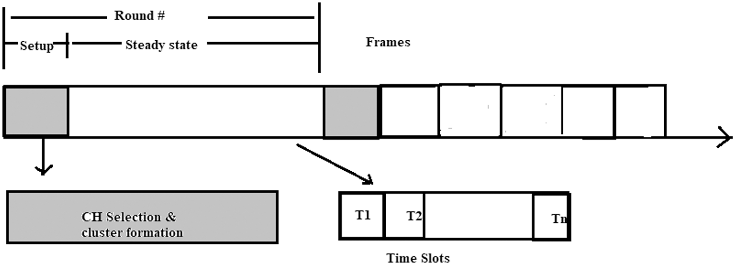
Figure 1: Random cluster head selection protocol
The Fig. 1 shows all these three stages. We have taken the energies consumed in the setting up of clusters, as the “extra energy utilization”, because these energies are not utilized in actual data transmissions from a sensor node to its CH or from a CH to the sink. The proposed system has considered this Extra energy (Eextra) as shown in Fig. 2.

Figure 2: Detail of random cluster head selection protocol and identification of extra energy consumption
Due to the characteristics of the underwater acoustic channel, the energy consumption model of UWSNs is quite different than the energy consumption model of terrestrial WSN. The energy model developed for the calculation of Eextra base on the following energy equation consider given below. Eqs. (2), (7) and (8) [33].
Energy consume for transmission of data given below
where Et = Energy consume in transmission. Eele = Energy consumed by the electronics for transmitting and receiving of 1 bit data measured in (j/b).
x = number of bits. And Pe is define as
where
where d = distance between transmitter and receiver. K = Spreading factor (for spherical spreading = 2 and or cylindrical spreading = 1) Practical value of k = 1.5 and Po is the power threshold that the data can be received by the node and ϑ is define as
where f(α
Sensor nodes consume energy to receive x bits of data
Sensor node consume energy for idle listening
where =
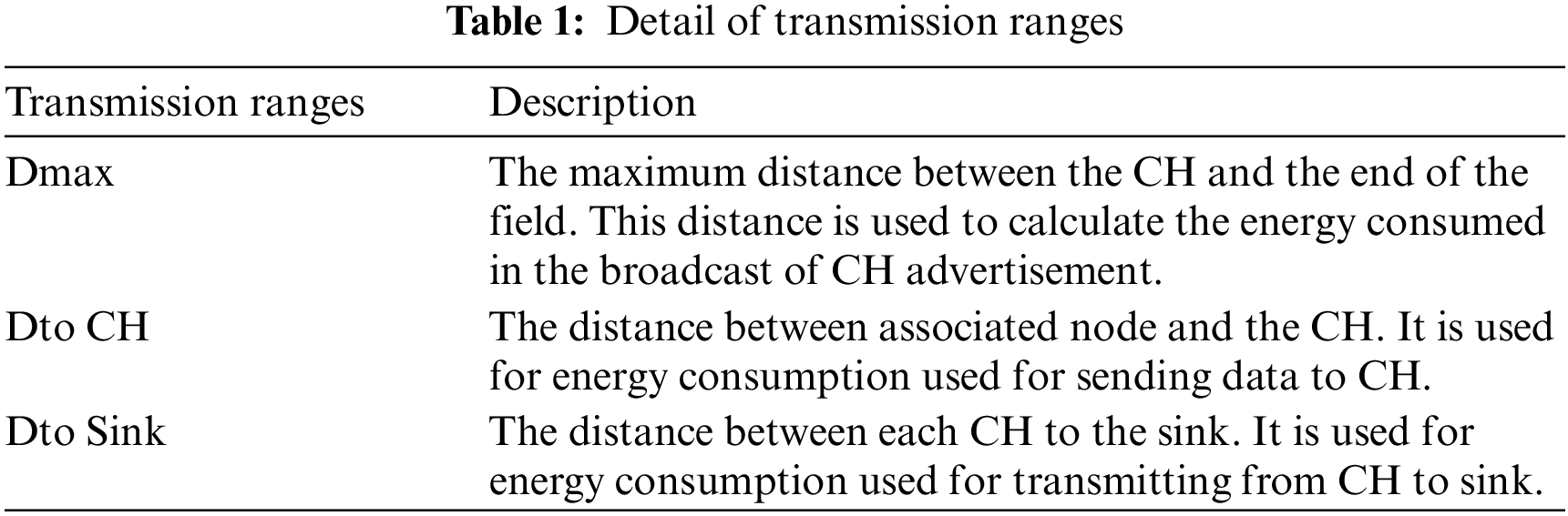
Different values of transmitted data x is taken such as xc = 25, xd = 250 and xt = xc + N size of the packet for TDMA schedule. Where xc is the control packet and xd is the data packet. Here Nodes per cluster is given as N. In each data delivery round, there are m data frames per cluster. We have taken its value as m = 20. Transmission ranges for each step of random cluster head selection algorithm are calculated is shown in Tab. 1.
During the contention stage, the communication between the cluster head and all nodes is accomplished by non-persistent CSMA. ρ is the throughput of non-persistence CSMA can be represented as [35].
In the above equation xc is the control packet size and
For our model under water propagation speed is taken as 1500 m/s. It is mentioned in the previous work that as the depth of the sea is varied from 0 meters to 1500 meters, the salinity of water and temperature, decreases, along with the sound speed while propagation delay is increased [35].
Transmission loss or transmission delay is the effective parameter for UW communication. It weakened the sound strength through the path from the transmitting node to receiving node in the network. Transmission loss is determined by the transmission range and attenuation. According to the thorp formula of attenuation, transmission loss is expressed in dB as [35].
f(α) is computed from above Eq. (6) and r is the transmission range in meter.
In our model speed of sound is 1500 m/s and propagation delay computed by using end to end delay model and it is 0.00066 s for 1 m, from Eq. (10) and value of parameter
For a control packet size xc of 25 Bytes, throughput for non-persistent CSMA ρ is 0.95. For the purpose of our simulations, we have considered the values of Eele as 50 nJ/bits (Because this value has been considered in many previous researches/simulations). We have also considered that initially each node (At its full capacity) has its energy as 10 joules. β = 0.8 is the ratio of energies consumed in data reception and idle listening modes [34,35].
4 Mathematical Channel Model for Extra Energy Calculation
In our simulation-based investigation, the Extra energy consumption has been considering carefully. At each step of each round, consider the transmissions of data and control packets. For different sizes of the network and the different numbers of the sensor node, the energy consumes in the cluster setup phase was calculated carefully. It can be inferred from the energy Eqs. (2) and (7) for the data transmissions and receptions respectively, there are two factors that dominantly affect the energy consumptions i.e., the distances between the transmitters and receivers (Transmission ranges) and the number of bits in data packets (Packet size).
Our proposed work, shows that we have three types of transmission ranges for each node separately shown in Tab. 1 and parameter and their values are shown in Tab. 2.
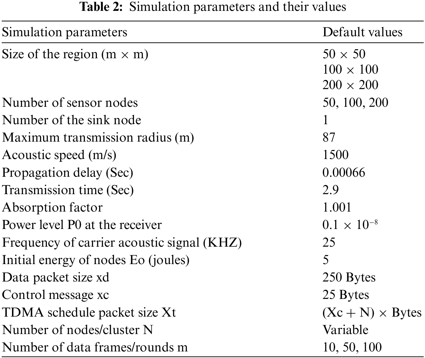
The model for UWSN for dynamic cluster head selection mechanism of 50, 100 and 200 sensor nodes was developed using MATLAB. The sink is placed at the center of varying sizes of the network. It is assumed that base on the power level or strength of the signal receiving node can estimate the distance between themselves and the transmitting node. The optimum value of cluster head formation is obtained with varying parameters such as the number of nodes, percentage of cluster head formation, and the different sizes of the network. Extra energy and remaining energy consumption can be calculated from this model.
In the simulation model calculations of energy consumption per round done as follows:
CH selection permission stage
Energy consumed for CH selection (CH to sink communication):
where, (p * n) is the average attempts per packet time; p is the maximum percentage of CH per rounds; n is the total number of nodes in the network; ρ is the throughput of non-persistence CSMA.
All CH broadcast its selection; all associated nodes are listening nodes and keep ON its channel.
Energy consumed at CH for broadcasting its advertisement to its associated nodes.
4.2 Steady State Stage (Contention Stage)
Energy consumed at all nodes to reply to get associated with CH and CH send TDMA schedule to its nodes.
Energy consumed in transmitting N frame to CH and then to transmitted aggregated data from CH to the sink.
Ni = number of associated nodes, m = number of frames for our simulation, Ni is taken as random. Except Eqs. (17) and (18) all other energies mention above in Section 4.1 and 4.2 are considered as Extra energy.
Let
Extra energy for R rounds
Efficient energy for R rounds:
Total energy consumed in R rounds:
5 Results of Simulation and its Analysis
Energy model for random cluster selection algorithm developed for UWSN in MATLAB. Simulation is performed 1000 times with varying value of cluster head formation, and it is observed Extra energy increased with the increase in the probability of cluster head formation. As shown in Fig. 3 at the 20 percent to 25 percent cluster head (CH) formation Extra energy is approximately the same. It shows at 5 percent cluster head formation; Extra energy is lower than others computed extra energies. And at this percentage of cluster head formation, it computes the best cluster head count for the network of 100 sensor nodes and prolong the life of the network. This optimum performance value of cluster head formation is the most appropriate from out of the total number of field sensor nodes and minimum energy consumed in cluster head formation. The maximum Extra energy is 12.9 percent (48 joules) occur at 33 percent of CH formation and at this CH formation, generated cluster head count is not suitable for the 100 nodes of the network. Network life, if define in terms of the number of nodes dies, the number of dead node increases as the percentage of cluster head formation increases shown in Fig. 3. As shown in figure number 3 of dead nodes and alive nodes are same at 20 to 25 percent of CH formation because the generated cluster head count is most suitable for the network.

Figure 3: Extra energy consumption of the network with percentage of cluster head formation
Fig. 4 shows the number of alive and dead nodes with the varying value of Cluster Head (CH) formation and shows that at 20 to 25 percent of CH formation number of dead nodes is same and it shows system stable for these percentage of CH formation and life of network remain same. At this extra energy consumption is approximately same i-e 44 joules. To show the effect of extra energy consumption, in Fig. 4 difference between efficient energy and total energy is developed. It shows that maximum Extra energy is 12.9 percent of the total energy used for the cluster head formation mechanism and its effect on the total consumed energy of the network. It also shown in Fig. 3, maximum extra energy of 48 joules occurs at 33 percent of cluster head formation and it will affect or reduce the life of the network.

Figure 4: Number of nodes dead/alive with percentage of cluster head formation in 1000 round of the network
To show the effect of extra energy consumption, in Fig. 4 difference between efficient energy and total energy is developed. It shows that maximum Extra energy is 12.9 percent of the total energy used for the cluster head formation mechanism and its effect on the total consumed energy of the network. It also shown in Fig. 3, maximum extra energy of 48 joules occurs at 33 percent of cluster head formation and it will affect or reduce the life of the network. At 5 percent of CH formation minimum extra energy consumes is 30.2 joules and the life of the network will prolong.
The summary of result discussed above is reference in a Tab. 3. To obtain the best result the 1000 rounds of computation have performed in MTLAB simulator with varying percentage of CH formation. It is found as shown in Tab. 3 that extra energy consumption increases as percentage of cluster head formation increases and decreases at optimum value of CH formation i-e at 5 percent cluster head. And number of dead nodes also increases with increase in cluster head formation and the number of CHs where it minimum is considered as the optimum number of CH formation. From the table it can be seen that it is 5 percent. The extra energy consumptions increases and nodes dying starts gradually after this number. This increase is because of a greater number of CH formations than an optimum value says 5 percent of the total number of nodes. Other transmission also affects energy utilization like broad cast messaging in CH setup time and transmission of control packet in contention period of cluster formation mechanism, therefore extra energy consume is also rises.
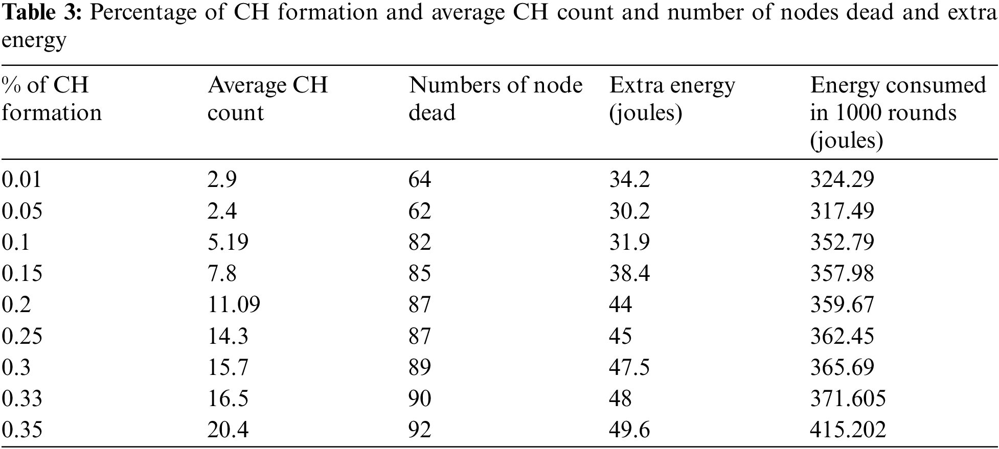
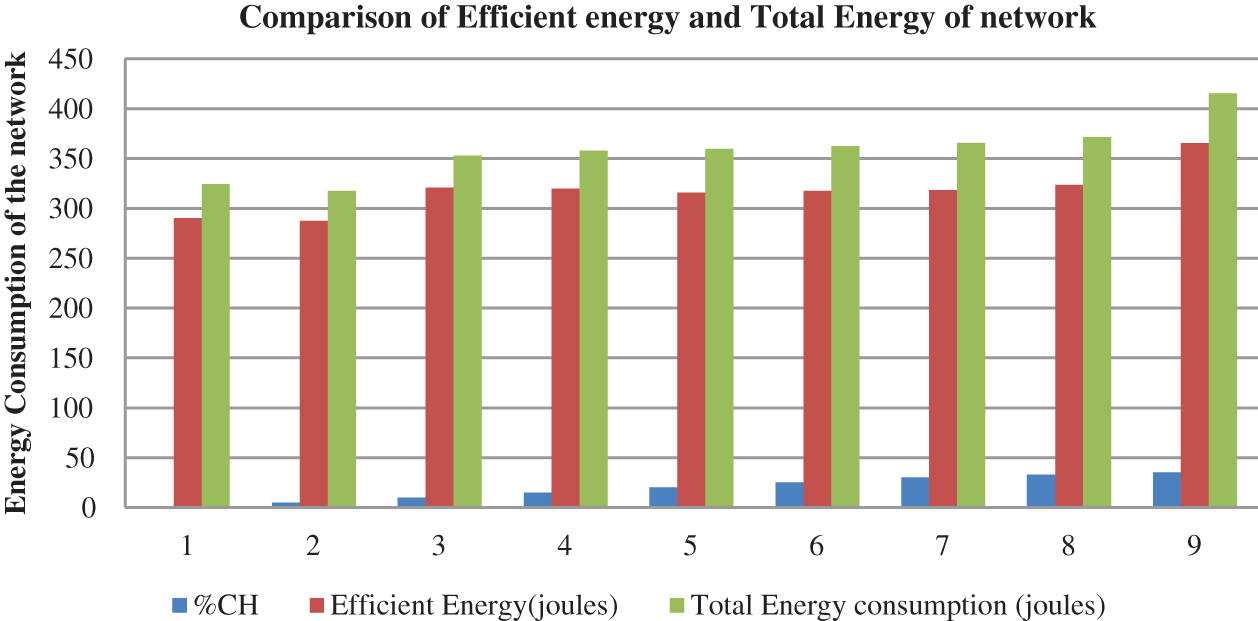
Figure 5: Comparison of efficient energy and total energy of the network
One of the main objectives of clustering is to balance the traffic load between the cluster head and the cluster nodes. Furthermore, this can be done by periodically re-clustering the network. However, the cost of clustering influences the network's performance, and the period of this process required a depth of knowledge and investigation. This investigation is conducted with the varying value of CH formation as shown in Tab. 1 and Fig. 4 and concludes that the energy consumption in the cluster head setup stage is an encumbrance in the random cluster head selection algorithm. This energy consumption is not used in communication and only used in the cluster setup is calculated as extra energy and proof that it is 12.9 percent of network energy. To prolong the network life underwater or conserve network energy, it is better to minimize the cluster setup stage and reduce the process of re-clustering. Further, as shown in Tab. 1 and Fig. 5, network life is optimum at 5% of cluster head formation, and extra energy is a reduced amount of energy. Based on the above analysis in the future, we have a plan to propose an energy-efficient clustering scheme to balance the load on sensor nodes or to synchronize the upcoming intelligent future networks [36–40] and IoT [41] to reduce the process of re-clustering instead of avoiding altogether.
Funding Statement: The authors received no specific funding for this study.
Conflicts of Interest: The authors declare that they have no conflicts of interest to report regarding the present study.
1. K. Ovaliadis and N. Savage, “Cluster protocols in underwater sensor networks: A research review,” Journal of Engineering Science and Technology Review, vol. 7, no. 3, pp. 171–175, 2014. [Google Scholar]
2. M. Mohsin, A. A. Sheikh, M. M. Asif, F. Emad and Q. Saad, “A survey on current underwater acoustic sensor network applications,” International Journal of Computer Theory and Engineering, IACSIT Press, vol. 7, no. 1, pp. 51–56, 2015. [Google Scholar]
3. F. Zhu and J. Wei, “An energy efficient routing protocol based on layers and unequal clusters in underwater wireless sensor networks,” Hindawi Journal of Sensors, vol. 2018, Art. no. 5835730, pp. 10, 2018. [Google Scholar]
4. R. B. Manjula and S. S. Manvi, “Issues in underwater acoustic sensor networks,” International Journal of Computer and Electrical Engineering, vol. 3, pp. 101–111, 2011. [Google Scholar]
5. A. Nayyar, V. Puri and L. D. Nhuong, “Comprehensive analysis of routing protocols surrounding underwater sensor networks (UWSNs)” In: V. Balas, N. Sharma, A. Chakrabarti, (Eds.Data Management, Analytics and Innovation. Advances in Intelligent Systems and Computing, Singapore: Springer, vol. 808, pp. 435–450, 2019. [Google Scholar]
6. H. Yan, Z. J. Shi and J.-H. Cui, “DBR: Depth-based routing for underwater sensor networks,” Lecture Notes in Computer Science (LNCS), vol. 4982, pp. 72–86, 2008. [Google Scholar]
7. S. M. Mazinani, H. Yousefi and M. Mirzaie, “A Vector-based routing protocol in underwater wireless sensor networks,” Wireless Personal Communications, vol. 100, no. 4, pp. 1569–1583, 2018. [Google Scholar]
8. J. M. Jornet, M. Stojanovic and M. Zorzi, “Focused beam routing protocol for underwater acoustic networks,” in Proc. of the 3rd ACM Int. Workshop on Wireless Network,Test Beds, Experimental Evaluation and Characterization (WuWNeT’08), San Francisco, CA, USA, pp. 75–82, 2008. [Google Scholar]
9. M. Ayaz and A. Abdullah, “Hop-by-hop dynamic addressing based (H2-DAB) routing protocol for underwater wireless sensor networks,” in Int. Conf. on Information and Multimedia Technology, Jeju Island, South Korea, pp. 436–441, 2009. [Google Scholar]
10. A. Wahid and D. Kim, “An energy efficient localization-free routing protocol for underwater wireless sensor networks,” International Journal of Distributed Sensor Networks, vol. 8, no. 4, art no. 307246, 2012. [Google Scholar]
11. Z. Yuan, T. Cao and W. Xiang, “Any path routing protocol design via q-learning for underwater sensor networks.” IEEE Internet of Things Journal, vol. 8, no. 10, pp. 8173--8190, 2020. [Google Scholar]
12. W. Zhiping, L. Shaojiang, N. Weichuan and X. Zhiming, “An energy-efficient multi-level adaptive clustering routing algorithm for underwater wireless sensor networks,” An energy-efficient multi-leveladaptive clustering routing algorithm for underwater wireless sensor networks, vol. 22, no. 6, pp. 14651--14660, 2019. [Google Scholar]
13. M. Ahmed, M. A. Soomro, S. Parveen, J. Akhtar and N. Naeem, “CMSE2R: Clustered-based multipath shortest distance energy efficient routing protocol for underwater wireless sensor network,” Indian Journal of Science and Technology, vol. 12, p. 8, 2019. [Google Scholar]
14. M. Ahmed, M. Salleh and M. I. Channa, “CBE2R: A clustered-based energy-efficient routing protocol for underwater wireless sensor network,” International Journal of Electronics, vol. 105, no. 11, pp. 1916–1930, 2018. [Google Scholar]
15. Z. Wang, “An energy aware and void avoidable routing protocol for underwater sensor networks,” IEEE Access, vol. 6, pp. 7792–7801, 2018. [Google Scholar]
16. N. Javaid, A. Majid, A. Sher, W. Z. Khan and A. Alsalem, “Avoiding void holes and collisions with reliable and interference-aware routing in underwater WSNs,” Sensors, vol. 18, no. 9, pp. 3038, 2018. [Google Scholar]
17. F. Zhu and J. Wei, “An energy efficient routing protocol based on layers and unequal clusters in underwater wireless sensor networks,” Hindawi Journal of Sensors, vol. 2018, art. no. 5835730, pp. 10, 2018. [Google Scholar]
18. I. Naveed, T. A. Alghamdi, M. N. Farooq, B. Mehboob, A. H. Sadiq, U. Qasim, Z. A. Khan and N. Javaid, “AEDG: Auv-aided efficient data gathering routing protocol for underwater wireless sensor networks,” ProcediaComputer Science, Science Direct, The 6th International Conference on Ambient Systems, Networks and Technologies, London, United Kingdom, vol. 52, pp. 568–575, 2015. [Google Scholar]
19. A. Khan, M. Khan, S. Ahmed, M. A. A. Rahman and M. Khan, “Energy harvesting based routing protocol for underwater sensor networks,” PLoS One, vol. 14, no. 7, p. e0219459, 2019. [Google Scholar]
20. Z. Ying, S. Hongliang and Y. Jiancheng, “Clustered routing protocol based on improved K- means algorithm for underwater wireless sensor networks,” in 2015 IEEE Int. Conf. on Cyber Technology in Automation, Control, and Intelligent Systems (CYBER), Shenyang, China, pp. 1304–1309, 2015. [Google Scholar]
21. Z. Zhou, B. Yao, R. Xing, L. Shu and S. Bu, “E-CARP: An energy efficient routing protocol for UWSNs in the internet of underwater things,” IEEE Sensors Journal, vol. 16, no. 11, pp. 4072–4082, 2016. [Google Scholar]
22. S. Basagni, C. Petrioli, R. Petroccia and D. Spaccini, “CARP: A channel-aware routing protocol for underwater acoustic wireless networks,” Ad Hoc Networks, vol. 34, pp. 92–104, 2015. [Google Scholar]
23. M. Ahmed, M. Salleh and M. I. Channa, “CBE2R: A clustered-based energy-efficient routing protocol for underwater wireless sensor network,” International Journal of Electronics, vol. 105, no. 11, pp. 1916–1930, 2018. [Google Scholar]
24. F. A. Salti, N. Alzeidi and B. R. Arafeh, “EMGGR: An energy-efficient multipath grid-based geographic routing protocol for underwater wireless sensor networks,” Wireless Networks, vol. 23, no. 4, pp. 1301–1314, 2017. [Google Scholar]
25. X. Xiao, H. Huang and W. Wang, “Underwater wireless sensor networks: Energy efficient clustering routing protocol based on data fusion and genetic algorithms,” Applied Sciences, vol. 11, p. 312, 2021. [Google Scholar]
26. D. Anuradha and S. K. Srivatsa, “Energy effectual reconfigurable routing protocol (e2r2p) for cluster based underwater wireless sensor networks,” Journal of Ambient Intelligence and Humanized Computing (JAIHC), vol. 2019, pp. 1868–5145, 2019. [Google Scholar]
27. M. T. Abbas, A. Muhammad and W. C. Song, “SD-IoV: SDN enabled routing for the internet of vehicles in the road,” Journal of Ambient Intelligence and Humanized Computing, vol. 11, pp. 1265–1280, 2020. [Google Scholar]
28. M. R. Haque, S. C. Tan, Z. Yusoff, K. Nisar and L. C. Kwang et al., “Automated controller placement for software-defined networks to resist ddos attacks,” Computers, Materials & Continua, vol. 68, no. 3, pp. 3147–3165, 2021. [Google Scholar]
29. G. Tuna, “Clustering-based energy-efficient routing approach for underwater wireless sensor networks,” International Journal of Sensor Networks (IJSNET), vol. 27, no. 1, pp. 26–36, 2018. [Google Scholar]
30. S. Karim, F. K. Shaikh, K. Aurangze, B. S. Chowdhry and M. Alhussein, “ANCRP for reliable data transfer in UWSN,” IEEE Access, vol. 9, pp. 36730–36747, 2021. [Google Scholar]
31. M. Ayaz, A. B. Abdullah and L. T. Jung, “Temporary cluster based routing for underwater wireless sensor networks,” Journal International Symposium on Information Technology, vol. 2, pp. 1009–1014, 2010. [Google Scholar]
32. M. Ahmed, M. Salleh and M. Ibrahim Channa, “CBE2R: Clustered-based energy efficient routing protocol for underwater wireless sensor network,” International Journal of Electronics, vol. 105, pp. 1916–1930, 2018. [Google Scholar]
33. R. N. Enam, M. Imam and R. I. Qureshi, “Energy consumption in random cluster head selection phase of WSN,” in 2012 IACSIT Hong Kong Conf. IPCSIT, Singapore, IACSIT Press, vol. 30, 2012. [Google Scholar]
34. S. H. Bouk, S. H. Ahmed and D. K. Kim, “Delay tolerance in underwater wireless communications: a routing perspective,” in Hindawi Publishing Corporation Mobile Information Systems, vol. 4, art. no. 6574697, pp. 9, 2016. [Google Scholar]
35. Y. Kularia, S. Kohli and P. P. Bhattacharya, “Analyzing propagation delay, transmission loss and signal to noise ratio in acoustic channel for underwater wireless sensor networks” in 2016 IEEE 1st Int. Conf. on Power Electronics, Intelligent Control and Energy Systems (ICPEICES), Delhi Technological University, pp. 1–5, 2016. [Google Scholar]
36. W. H. Bangyal, A. Hameed, J. Ahmad, K. Nisar, M. R. Haque et al., “New modified controlled Bat algorithm for numerical optimization problem,” Computers, Materials & Continua, vol. 70, no. 2, pp. 2241–2259, 2022. [Google Scholar]
37. K. Nisar, E. R. Jimson, M. H. A. Hijazi, I. Welch, R. Hassan et al., “A survey on the architecture, application, and security of software defined networking,” Internet of Things, vol. 12, pp. 1–27, 2020. [Google Scholar]
38. J. Shuja, R. W. Ahmad, A. Gani, A. I. A. Ahmed, K. Nisar et al., “Greening emerging it technologies: Techniques and practices,” Journal of Internet Services and Applications, vol. 8, no. 9, pp. 01–11, 2017. [Google Scholar]
39. M. R. Haque, S. C. Tan, Z. Yusoff, K. Nisar, C. K. Lee et al., “A novel DDoS attack-aware smart backup controller placement in SDN design,” Annals of Emerging Technologies in Computing, vol. 4, no. 5, pp. 75–92, 2020. [Google Scholar]
40. M. R. Haque, S. C. Tan, Z. Yusoff, K. Nisar, R. Kaspin et al., “Unprecedented smart algorithm for uninterrupted sdn services during DDoS attack,” Computers, Materials & Continua, vol. 70, no. 1, pp. 875–894, 2022. [Google Scholar]
41. Z. Sabir, K. Nisar, M. A. Z. Raja, M. R. Haque and M. Umar, “IoT technology enabled heuristic model with morlet wavelet neural network for numerical treatment of heterogeneous mosquito release ecosystem,” IEEE Access, vol. 9, pp. 132897–132913, 2021. [Google Scholar]
 | This work is licensed under a Creative Commons Attribution 4.0 International License, which permits unrestricted use, distribution, and reproduction in any medium, provided the original work is properly cited. |