DOI:10.32604/cmc.2022.023397
| Computers, Materials & Continua DOI:10.32604/cmc.2022.023397 | |
| Article |
A Compact 28 GHz Millimeter Wave Antenna for Future Wireless Communication
1LCOMS, ASEC, University de Lorraine, Metz, 57070, France
2Department of Electrical and Computer Engineering, Comsats University Islamabad, Abbottabad Campus, 22060, Pakistan
3Electrical Engineering Department, Bahauddin Zakariya University, Multan, 60800, Pakistan
4Department of Electronics Technology, University of Technology, Nowshera, 24100, Pakistan
5Department of Electrical Engineering, National University of Sciences and Technology, H-12, Islamabad, 44000, Pakistan
6Smart Systems Engineering Laboratory, College of Engineering, Prince Sultan University, Riyadh, 11586, Saudi Arabia
7Department of Information Technology, College of Computer and Information Sciences, Princess Nourah bint Abdulrahman University, P.O. Box 84428, Riyadh, 11671, Saudi Arabia
8Computer Software Engineering, Military College of Signals, National University of Sciences and Technology, Islamabad, 44000, Pakistan
*Corresponding Author: Mohamed Marey. Email: mfmmarey@psu.edu.sa
Received: 06 September 2021; Accepted: 09 December 2021
Abstract: This article presents a novel modified chuck wagon dinner bell shaped millimeter wave (mm-wave) antenna at 28 GHz. The proposed design has ultra-thin Rogers 5880 substrate with relative permittivity of 2.2. The design consists of T shaped resonating elements and two open ended side stubs. The desired 28 GHz frequency response is achieved by careful parametric modeling of the proposed structure. The maximum achieved single element gain at the desired resonance frequency is 3.45 dBi. The efficiency of the proposed design over the operating band is more than 88%. The impedance bandwidth achieved for −10 dB reference value is nearly 2.9 GHz. The proposed antenna is transformed into four element linear array which increases the gain up to 10.5 dBi. The fabricated prototype is tested for the measured results. It is observed that measured results closely match the simulated results. By considering its simple structure and focused radiation patterns, the proposed design is well suited for IoT (Internet of Things), mmWave microwave sensing, 5G and future RF (Radio Frequency) front-ends.
Keywords: RF front-ends; mmWave; partial ground plane; 28 GHz; IoT; 5G antenna
In the modern communication era, 5th Generation (5G) networks are of great interest due to their high speed and reliability over the communication link [1,2]. The millimeter-wave 5G technology delivers low latency and higher data rates than its predecessor 3rd Generation (3G), 4th Generation (4G) wireless communication technology [3]. This helps to easily entertain the number of increased user mobile terminals. Due to the high utilization of sub 6 GHz spectrum, the millimeter-wave spectrum due to its availability and tendency to support the massive data rates has achieved a prominent position for future RF technology [4]. However, as the wavelength in the millimeter-wave range becomes critically small, the atmospheric changes become crucial for millimeter-wave spectrum [5,6]. In order to overcome the impact of the atmospheric conditions, a millimeter-wave antenna with focused radiation patterns and higher gain is strongly recommended [7]. The target 5G requirements such as high gain, directivity and beam steering are achieved through the array configuration.
Recently, researchers have shown great interest in millimeter-wave 5G antennas and therefore, several antennas have been proposed for millimeter-wave 5G spectrum. They include planar and substrate integrated waveguide (SIW) fed structures. The SIW based design offer better bandwidth characteristics [7,8]. A SIW fed antenna array is presented in [7] for mmWave 28 GHz applications. The array has achieved a good gain of 12 dBi with 34.5% impedance bandwidth with overall physical dimensions of 45 × 20 mm2. The problem with this design is the large size and complex structure. A four-element SIW fed antenna array with dual polarization response has been reported in [9]. The antenna array has shown some good results but presence of the metallic via has made the design complex and difficult for real time application. Similarly, in [10] an Air field SIW fed antenna array is presented and discussed in detail. The reported structure has three layers namely radiating, cavity and lastly a fed layer through which an antenna is excited. The antenna array is compact in size but the bonding films nature between the layers minimize its usefulness in practical applications.
In mmWave communication systems, the bulky and complex nature of the SIW based designs are not considered the ideal candidates for its practical use. Simple planar antennas on the other hand are simpler, easy in fabrication and cost effective [11–16]. In [11] a snowflake shape simple planar antenna for mmWave applications is discussed in detail. The proposed structure has shown a good gain of 2.3 dBi with dual beam response for single element, while a 10 dBi gain is achieved for four element linear array. Although the proposed design has good performance but the large size highly reduces its usefulness for the target wireless applications. A four elements array is presented in [12]. The proposed design has shown a dual beam radiation patterns with high gain of 11.5 dBi. The size of the antenna is compact but the complex nature of the design makes it difficult of its use in mmWave applications. In [13] a SIW antenna is presented with size of 33 mm × 27 mm. Although the antenna exhibits a peak gain of 11.1 dBi at 27.6 GHz resonance but the proposed design has relatively narrow bandwidth. Similarly, in [14], the proposed design has a compact and simple design but the bandwidth response is only 1.2%. The proposed array design in [15] has shown promising results. The overall size of the proposed design is 28.8 mm × 60 mm which is quite large for mmWave applications. In [16] a cavity based multilayered antenna with array configuration is discussed in detail. The design has 13.97 dBi peak gain and 2.3 GHz operating bandwidth. The design has 70 × 63.5 mm2 size. This size is very large for mm-wave wireless applications. In [17] a simple phased array of series-fed patches for 28 GHz mm-wave application is presented. The design has a smaller size with the good gain. However, the operating band is very narrow for 5G applications.
Based on the above literature, a compact array design with compact size, wide impedance bandwidth and high gain was highly demanded. This work presents a simple and novel four element modified chuck wagon dinner bell shaped mmWave antenna array. The novelty of the proposed design is it compact and simple structure. The proposed work consists of open stubs which help to tune the antenna at desired frequency response. Additionally, the proposed work has focused radiation patterns with high gain for the four element feed network. A strong agreement between the simulated and measured results makes the proposed work a potential candidate for the 5G communication systems. Moreover, it can also be useful in sensing, tracking, and internet of things (IoT) wireless applications.
The proposed antenna is designed on an ultra-thin Roger (RO5880) substrate with 0.254 mm and 2.2 relative permittivity and 0.0027 loss tangent. The top and bottom view of the proposed antenna design single unit is shown in Fig. 1. The antenna has an overall 10 mm × 12 mm compact size. At the top of feed line, a T shaped resonator is introduced which is accompanied by two bended open stubs. These stubs help in resonating the design at the desired resonance frequency. The proposed antenna design has a partial ground plane. As shown in Fig. 1, a small square notch on the top middle of the ground plane is also introduced. A simple microstrip line excites the antenna. The detail of the optimized parameters of the proposed structure is shown in Tab. 1. As shown in Tab. 1, the width of all the resonating strips is set to 0.25 mm. This highly reduces the involvement of the metallic structure at high frequencies which improves the radiation efficiencies and gain of the design at operating bandwidth.
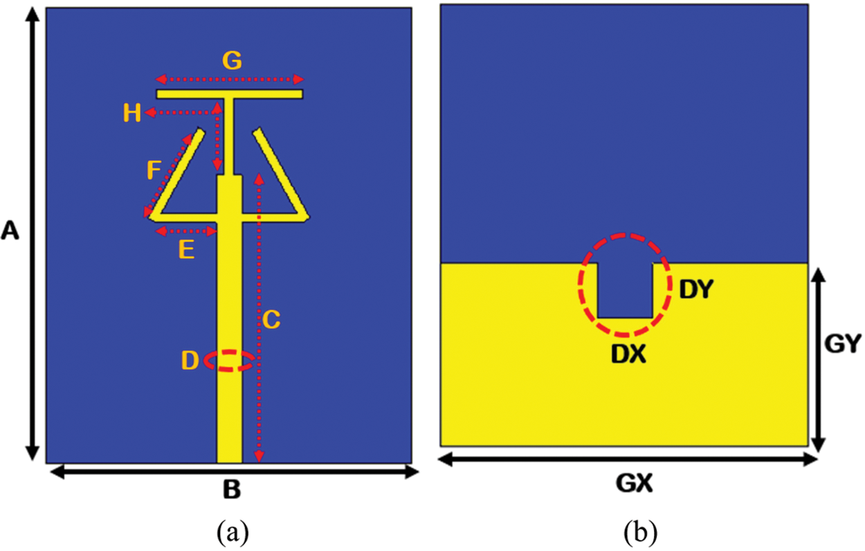
Figure 1: (a) Proposed antenna front view (b) proposed design bottom view
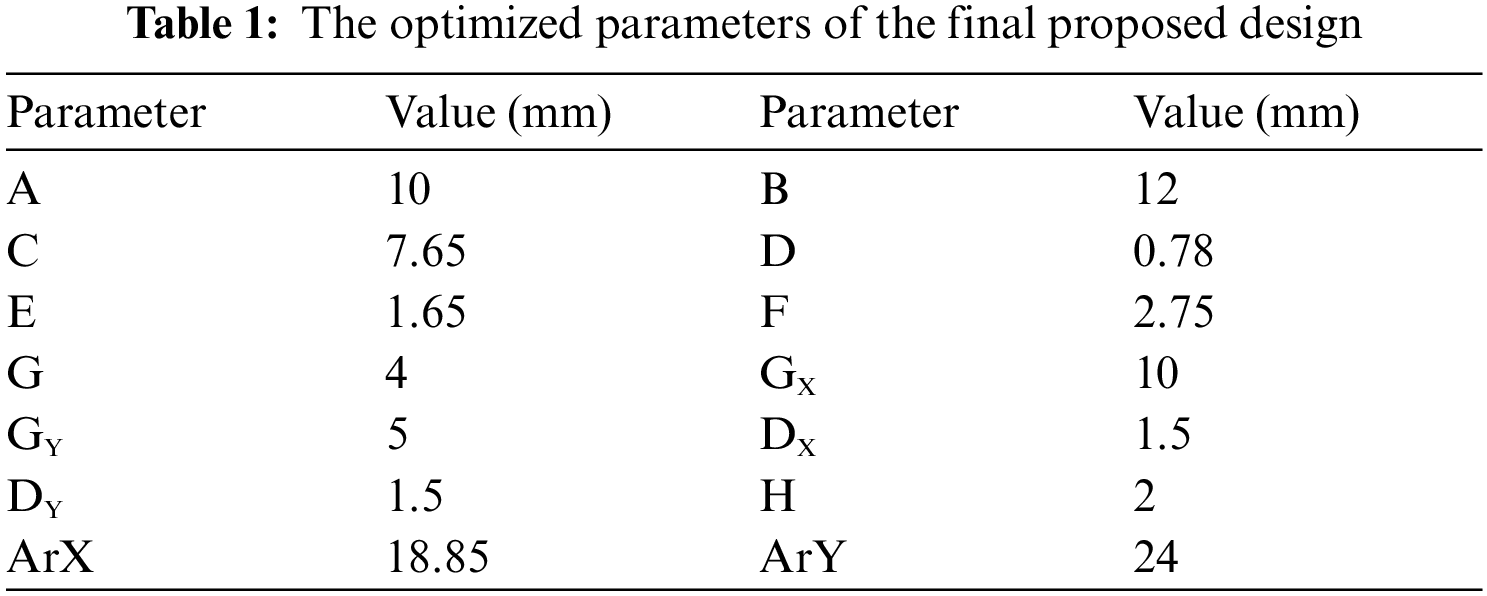
The evolution steps of the proposed design are shown in Fig. 2. The proposed design is finalized in three steps. Initially a vertical thin strip line is added to the feedline. At this stage, the design has a very poor impedance matching. No specific resonance frequency is achieved at this stage. In step two, a thin horizontal strip line is added to the top of the vertical strip line. This slightly improve the impedance matching but still the design is not resonating at the desired resonance frequency. Finally, in the third step, two semi triangles are added to the both sides of the vertical strip line. This step not only improve the impedance matching but also help in achieving the desired resonance frequency. At this step, the design resonates at 28 GHz. The proposed design final shape resembles a modified form of chuck wagon dinner bell. The semi triangles on both sides of the vertical strip line are bent to certain at 30°. This specific pattern helps to achieve the desired resonance frequency.
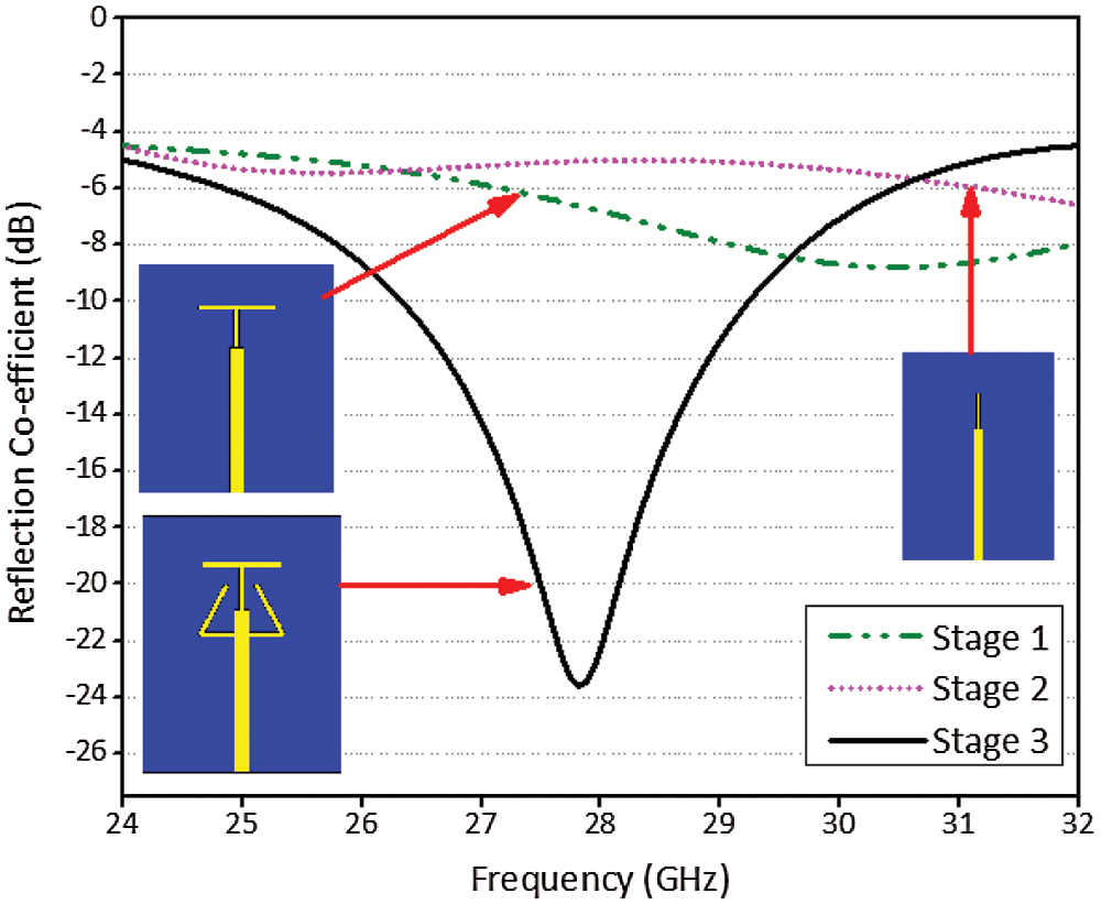
Figure 2: Different evolution steps of the proposed design
The proposed antenna parameters are carefully analyzed. The important parameters are the bending angles of the triangular open stubs, changing the rectangular ground plane notch width and length, changing the ground plane length and width. The open-ended strips at the right and left sides of the design are gradually changed with 10° bend angle. This bend changes the current pattern flow in the strips and different resonance responses are achieved as shown in Fig. 3. At 0° bend, the strip line vertically oriented, this arrangement generates the higher order modes in the antenna. The higher order modes resonate the design at 30 GHz. By increasing the bending angles, lower order modes are generated in the design which shift the resonance to left. At 30° bending angle, the antenna resonates at 28 GHz with 2.9 GHz operating bandwidth from 26.4 to 29.3 GHz. At this stage, the design has a good impedance matching with −23 dB return loss value. Similarly, the small square cut at the top of partial ground plane is optimized for enhancing the performance of the design. This analysis is shown in Figs. 4 and 5. The cut has an important role in tuning the resonance response. The square slot value is optimized with a step size of 0.25 mm. At 1.5 mm slot width, the design offers better impedance matching.
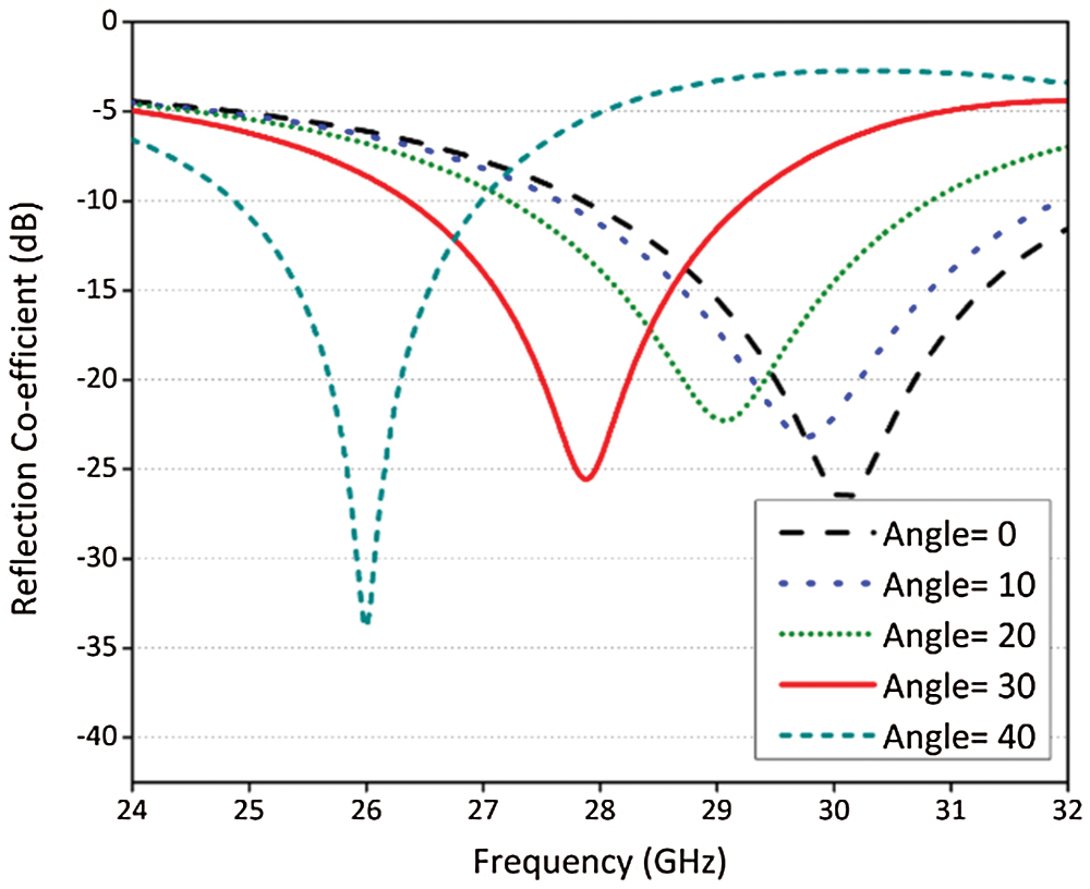
Figure 3: Shows the effect of orientation angle of the open ended strips
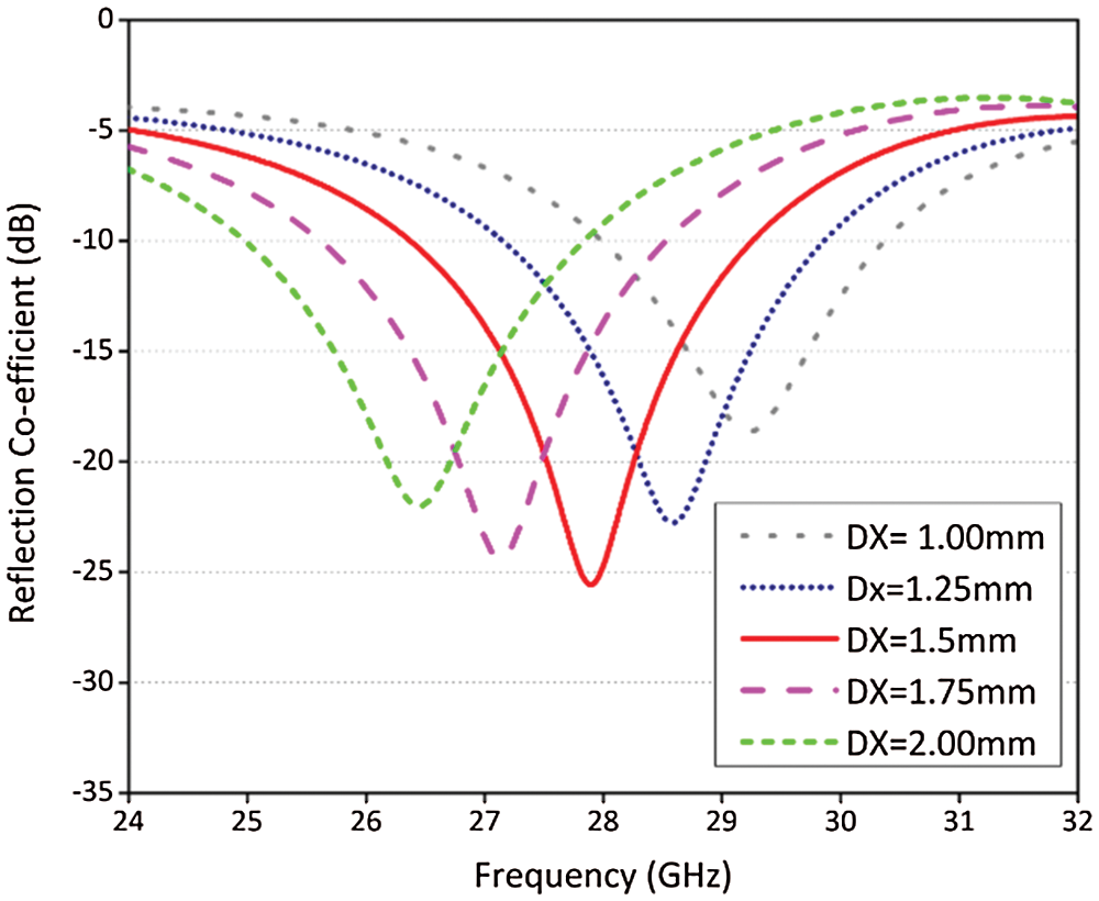
Figure 4: Shows the effect of the ground cut width on the reflection coefficients
Fig. 5 shows the impact of increasing and decreasing the ground cut length on the reflection coefficients. From the parametric analysis graph, it is clear that increasing the length of the ground plane cut effect both the impedance matching and resonance frequency. Initially a gradual decrease in the ground cut width shift right the resonance frequency. The maximum impedance matching is achieved at 1.75 mm ground cut length. To achieve 28 GHz target resonance frequency, the ground cut is further decreased to 1.5 mm. Any further decrease in the ground length not only degrade the impedance matching but also highly degrade the impedance matching. Thus 1.5 mm is the final ground cut length.
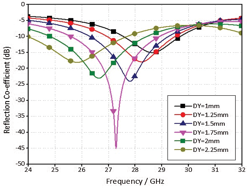
Figure 5: Shows the effect of the ground cut length on the reflection coefficients
Fig. 6 shows the impact of the ground length on the reflection coefficients. It is clear that increasing the ground length shifts the operating band to right and also reduces the impedance matching. With the ground length of 5 mm, the target resonance frequency of 28 GHz with −24 dB value of the reflection coefficient is achieved. Further increase in the ground length further reduces the impedance matching and shift right the resonance frequency.
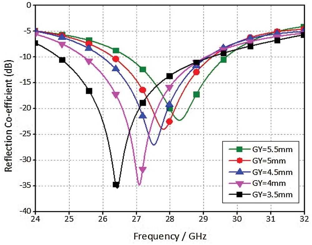
Figure 6: Shows the effect of the ground length on the reflection coefficients
Fig. 7 shows the effect of ground plane width on the return loss. Any decrease in the ground plane does not significantly change the impedance matching. A minor left shift in the resonance frequency is noticed with the decrease in the ground plane. Thus, to keep the operating band at the required resonance frequency, the ground plane is kept with its maximum value as that of the substrate.
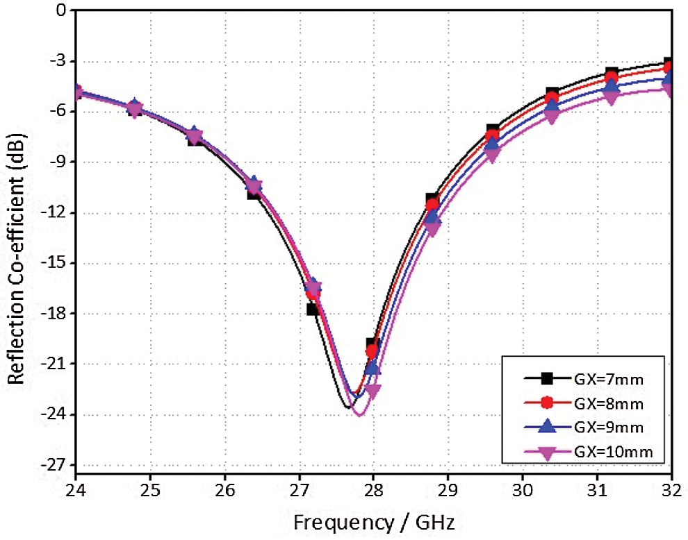
Figure 7: Shows the effect of the ground width on the reflection coefficients
2.2 Surface Current Distribution on Single Unit
Surface current distribution gives a good idea of electric field intensity on different parts of the design. Fig. 8 shows the current distribution on different part of the proposed design. It is clear from the figure that at resonance frequency current is highly focused on the feed line and radiator. While a low current activity is witnessed on the ground plane. This shows that altering the feedline length and different dimensions of the patches will alter the resonance frequencies and operating bandwidth.
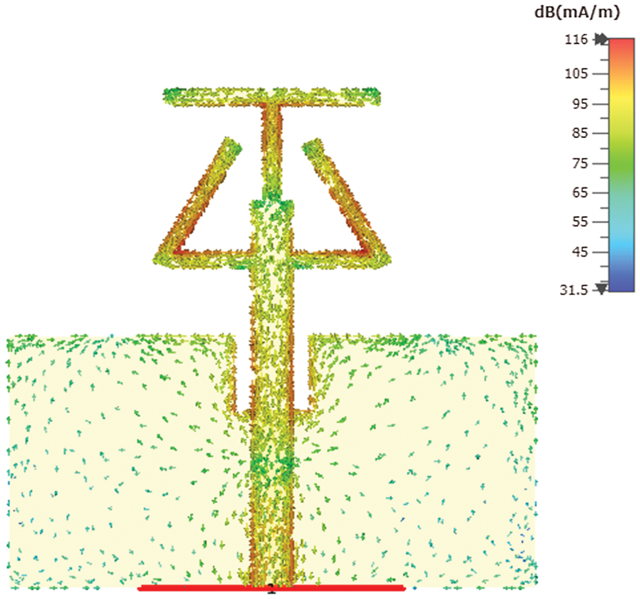
Figure 8: Surface current distribution of the proposed design at 28 GHz frequency
High gain is the requirement of modern wireless communication systems. This helps to overcome the atmospheric losses and fading during communication. For 5G wireless communication technology a gain of 10 dBi is the minimum requirement [1]. To meet the gain requirement, proposed antenna is transformed in to four element linear array system. As shown in Fig. 9, the array is designed by using a simple feeding network. A 50 Ω feedline with 0.9 mm width is splitted into two feedlines of 100 Ω. The width of 100 Ω line is kept 0.3 mm. In order to feed four elements of the design, the feedline is further divided into four feedlines of 70.7 Ω with 0.54 mm thickness. This arrangement of the feed network ensures equal power distribution to all radiating elements. On the bottom side of the design a rectangular ground notch also supports each radiating element. Fig. 10 shows the current distribution on the four element linear array. From the figure it is clear that when the design is excited, the current is focused on the feedlines and radiating elements. Some current activity is also noticed on the rectangular notches of the ground plane. These notches are made symmetrically beneath the each feedline.
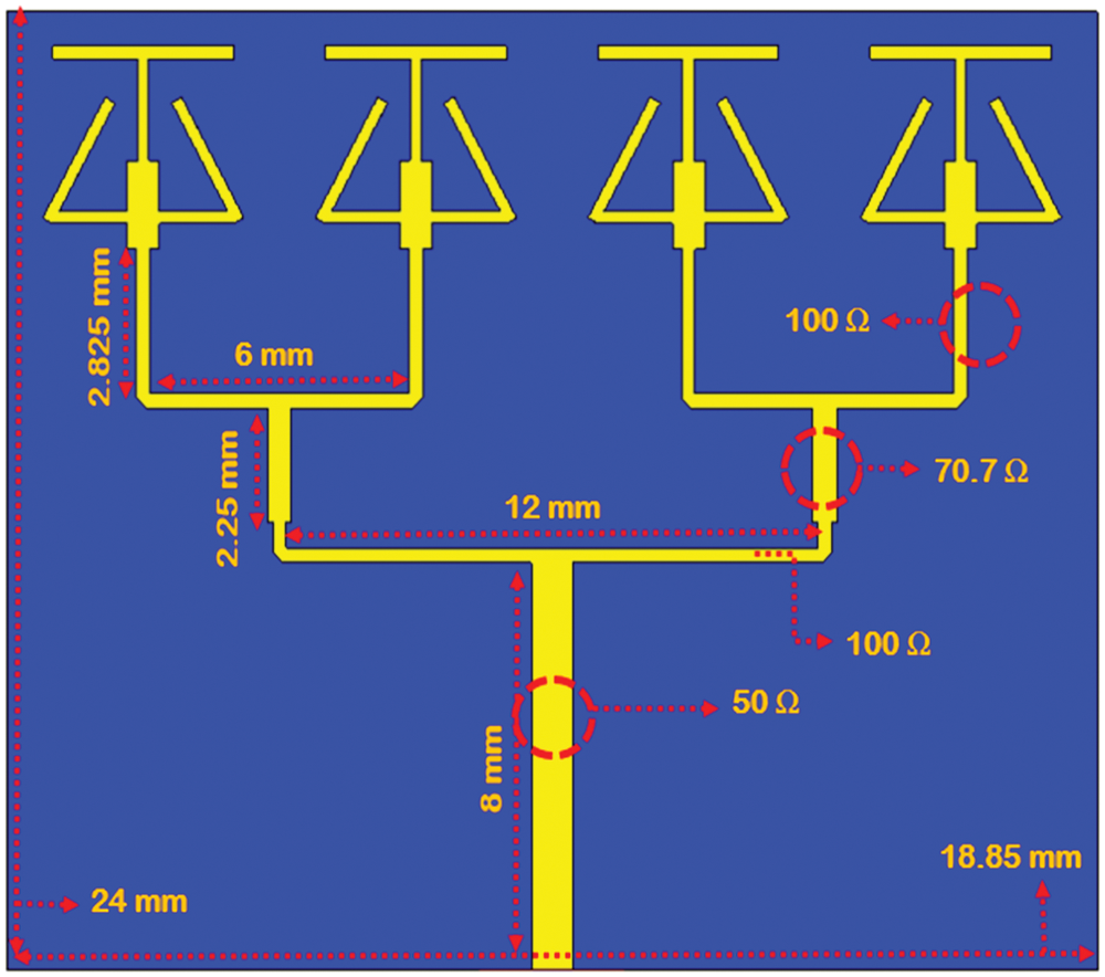
Figure 9: Proposed antenna array configuration with overall dimensions
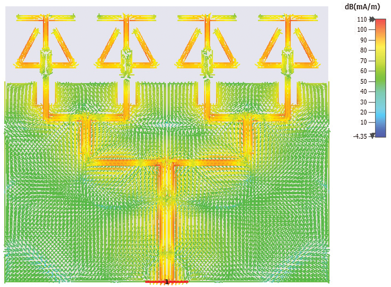
Figure 10: Surface current distribution of array configuration
The proposed antenna is fabricated and tested for the validation of the simulated results. Fig. 11 shows the simulated and measured reflection coefficient of the proposed four elements linear antenna array. From the figure, it is obvious that the simulated results closely resemble with the measured results. The measured impedance bandwidth for −10 dB reference value is 2.93 GHz. The achieved bandwidth is enough to cover the 5G mmWave wireless applications. The radiation patterns in terms of E-field and H-field are also measured. As shown in Fig. 13, the radiation pattern of the proposed design is measured in an anechoic chamber. Fig. 13 shows the simulated and measured radiation patterns at 28 GHz. At Phi 90° plane the main beam of the far field pattern is broadside and is focused towards −29° with the angular width of 33°. In Phi 0° plane, the main beam is pointed towards 0° and 180°, producing dual beam response with narrow angular beam width of 22.6°. Fig. 14 shows the antenna efficiency response and gain at the selected frequency points. The measured efficiency of the proposed design at the resonance frequency is 96%. The overall value of efficiencies is greater than 84% throughout the desired the operating band. The peak measured array gain at 28 GHz is 10.1 dBi. The Voltage Standing Wave Ratio (VSWR) value in the entire operational bandwidth is below 2. The directivity is 10.7 dBi at the central frequency which is shown in Fig. 15. The far field radiation pattern setup is shown in Fig. 12.
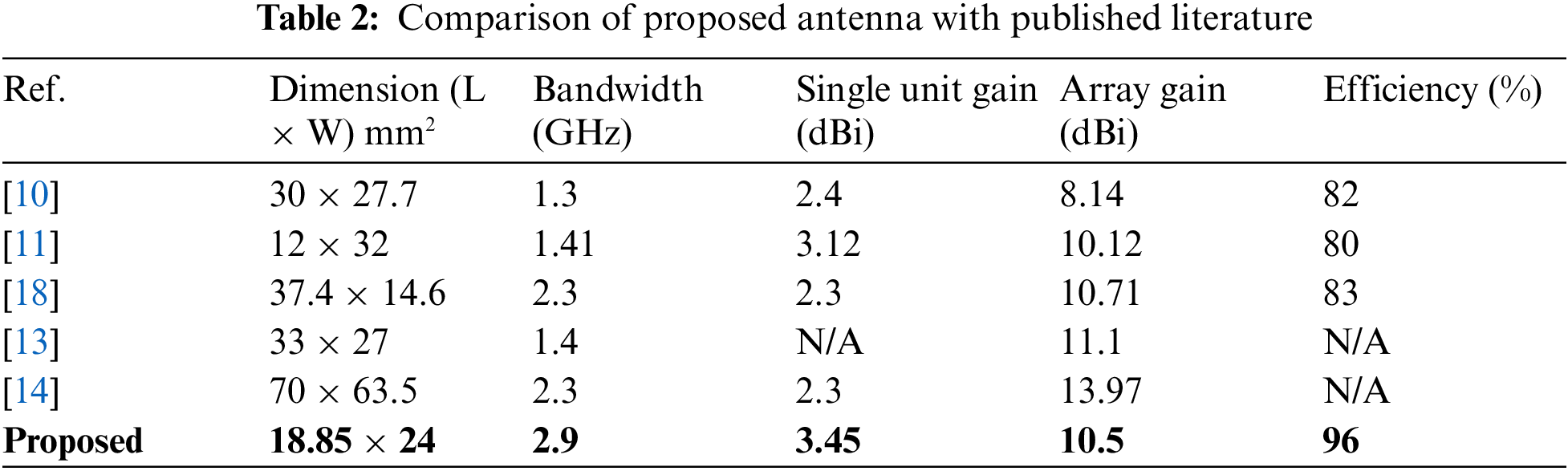
In Tab. 2, the proposed design is compared with the state of the art published literature. The comparison is based on the achieved operational bandwidth, gain, the antenna size and efficiency. From the table it is clear that the proposed array is compact since the dimensions in terms of length and width are less than the reported literature. The achieved bandwidth for the proposed design is 2.9 GHz which sufficient for the 5G applications. Moreover, the bandwidth of the proposed design is also lager than the designs in the comparison table. In [10] a SIW based phased array has reasonable efficiency and operating bandwidth. The drawback of this design is complex architecture, low gain and relatively larger volume. In [11] a compact fractal snowflake design has a good operating band and gain. However the bandwidth of the antenna is very low. From the table it is evident that proposed antenna design is well suited and a better candidate for future mmWave RF front-ends.
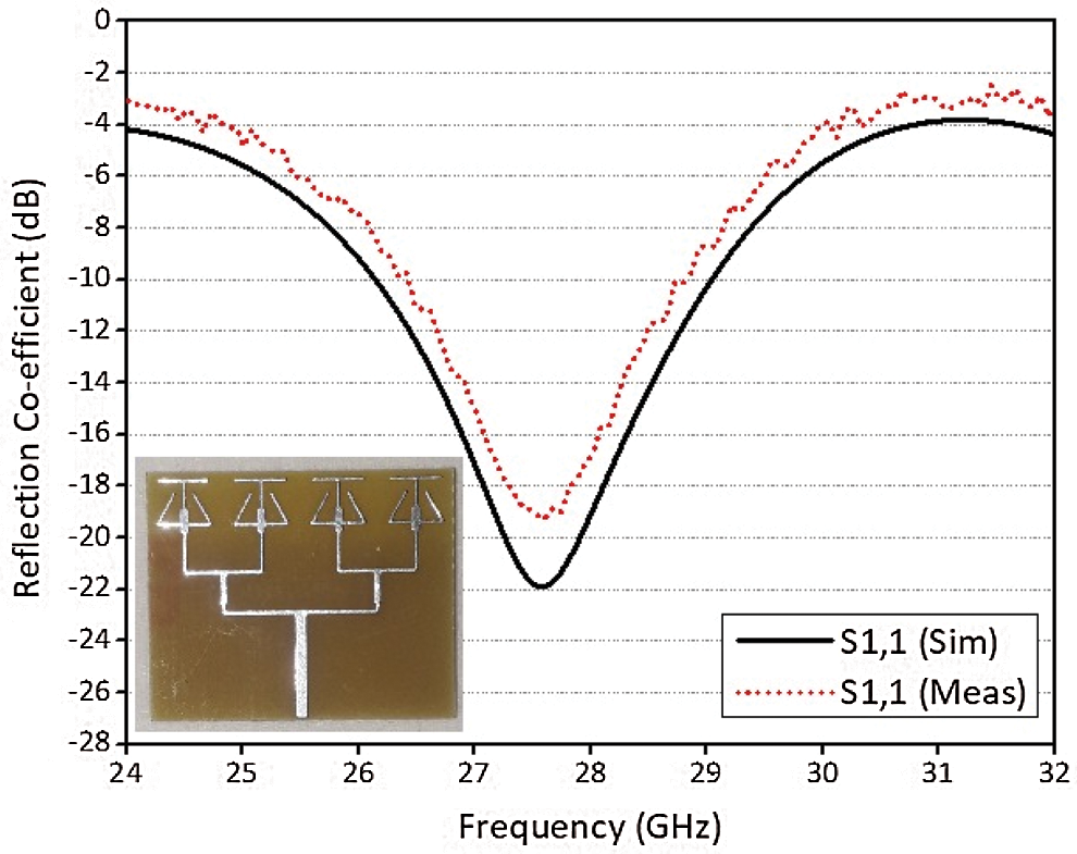
Figure 11: Measured and simulated reflection co-efficient of the proposed antenna array
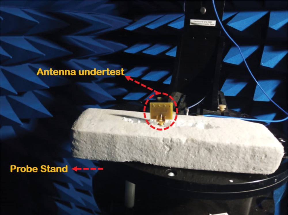
Figure 12: Far field radiation pattern set-up at 28 GHz
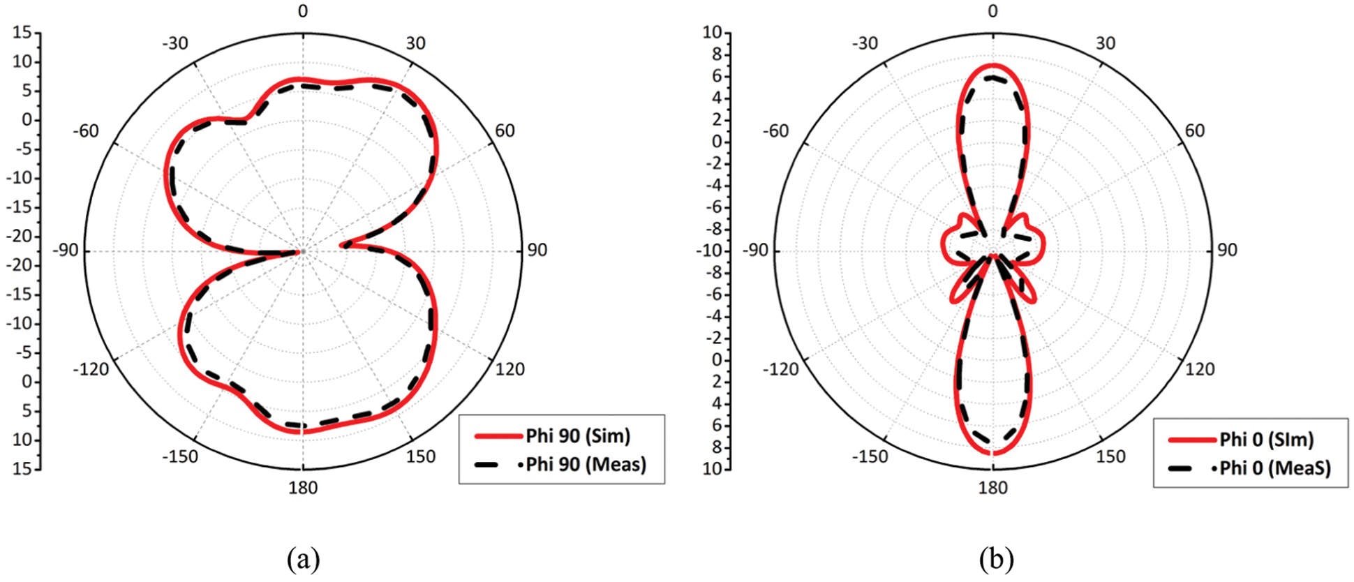
Figure 13: Simulated and measured radiation pattern at 28 GHz (a) Phi-90 (b) Phi-0
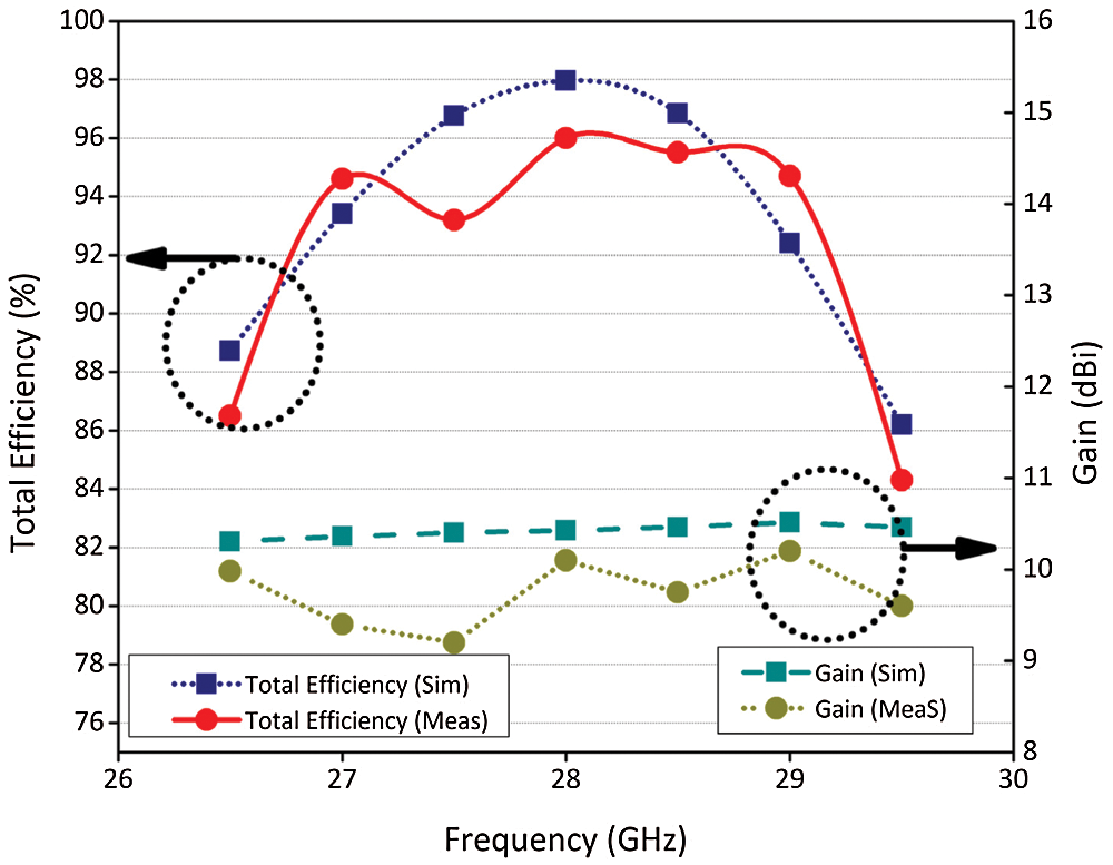
Figure 14: Simulated and measured gain and radiation efficiencies of the proposed antenna system
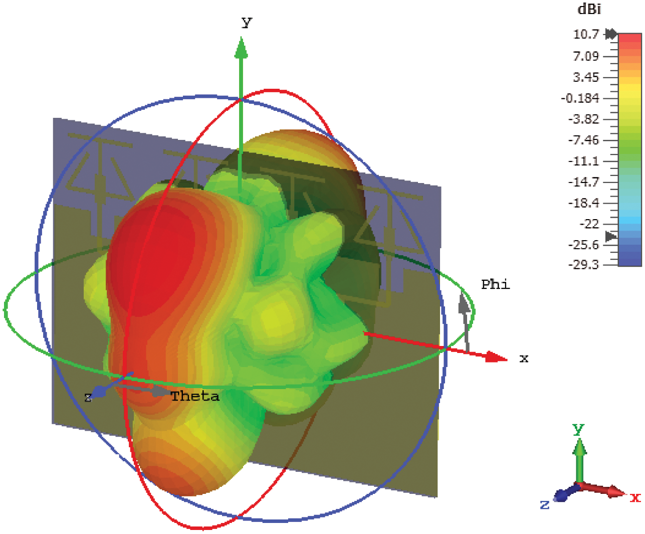
Figure 15: Directivity 3D view of proposed antenna array
This work presented a compact four element linear array or 5G wireless communication. The single unit of four element array is very simple with two open stubs and a top horizontal strip. The open end stubs are bent at 30°. This arrangement helps to achieve the desired resonance frequency and operating band with good impedance matching. The achieved impedance bandwidth for −10 dB criteria is 2.9 GHz. With the simple feeding structure, the proposed single element antenna design was transformed into four element linear array system. The proposed design has a high array gain of 10.1 dBi. The E-field radiation pattern of the proposed design is narrow. The design has 97% radiation efficiency at resonance frequency. The fabricated prototype has shown a good agreement with the simulated results. Based on the achieved results, the proposed antenna will prove a potential candidate for future mmWave, IoT and RF front-ends.
Acknowledgement: Princess Nourah bint Abdulrahman University Researchers Supporting Project number (PNURSP2022R137), Princess Nourah bint Abdulrahman University, Riyadh, Saudi Arabia. The authors would like to acknowledge the support of Prince Sultan University for paying the Article Processing Charges (APC) of this publication.
Funding Statement: The authors would like to acknowledge the support of Prince Sultan University for paying the Article Processing Charges (APC) of this publication. This research was funded by the Deanship of Scientific Research at Princess Nourah bint Abdulrahman University through the Fast-track Research Funding Program.
Conflicts of Interest: The authors declare that they have no conflicts of interest to report regarding the present study.
1. M. Bozic, M. Cabarkapa, D. Barjamovic and D. Budimir, “Waveform comparison and PA nonlinearity effects on CP-OFDM and 5G FBMC wireless systems,” Microwave and Optical Technology Letters, vol. 60, no. 8, pp. 1952–1956, 2018. [Google Scholar]
2. M. Khalily, R. Tafazolli, P. Xiao and A. A. Kishk, “Broadband mmWave microstrip array antenna with improved radiation characteristics for different 5G applications,” IEEE Transactions on Antennas and Propagation, vol. 66, no. 9, pp. 4641–4647, Sep. 2018. [Google Scholar]
3. J. Park, D. Choi and W. Hong, “28 GHz 5G dual-polarized end-fire antenna with electrically-small profile,” in 12th European Conf. on Antennas and Propagation (EuCAP), London, UK, pp. 1–4, 2018. [Google Scholar]
4. U. Ullah, I. B. Mabrouk, S. Koziel and M. Al-Hasan, “Implementation of spatial/polarization diversity for improved-performance circularly polarized multiple-input-multiple-output ultra-wideband antenna,” IEEE Access, vol. 8, pp. 64112–64119, 2020. [Google Scholar]
5. B. Feng, L. Li, K. L. Chung and Y. Li, “Wideband widebeam dual circularly-polarized magnetoelectric dipole antenna/array with meta-columns loading for 5G and beyond,” IEEE Transactions on Antennas and Propagation, vol. 69, no. 1, pp. 219–228, 2020. [Google Scholar]
6. S. Zhu, H. Liu, Z. Chen and P. Wen, “A compact gain-enhanced vivaldi antenna array with suppressed mutual coupling for 5G mm-wave application,” IEEE Antennas Wireless Propagation Letters, vol. 17, no. 5, pp. 776–779, May 2018. [Google Scholar]
7. Z. Pi and F. Khan, “An introduction to millimeter-wave mobile broad-band systems,” IEEE Communication Magazine, vol. 49, no. 6, pp. 101–107, 2011. [Google Scholar]
8. Y. Cheng and Y. Dong, “A compact folded SIW multibeam antenna array for 5G millimeter wave applications,” Microwave and Optical Technology Letters, vol. 63, no. 4, pp. 1236–1242, 2021. [Google Scholar]
9. J. Zhang, K. Zhao, L. Wang, S. Zhang and G. F. Pedersen, “Dual-polarized phased array with end-fire radiation for 5G handset applications,” IEEE Transactions on Antennas and Propagation, vol. 68, no. 4, pp. 3277–3282, 2020. [Google Scholar]
10. K. K. Yavuz, S. Lemey and H. Rogier, “Dual-polarized 28-GHz air-filled SIW phased antenna array for next-generation cellular systems,” in IEEE Int. Symp. on Phased Array System & Technology (PAST), Waltham, MA, USA, IEEE, 2019. [Google Scholar]
11. H. Ullah and F. Tahir, “A novel snowflake fractal antenna for dual-beam applications in 28 GHz band,” IEEE Access, vol. 8, pp. 19873–19879, 2020. [Google Scholar]
12. H. Ullah and F. A. Tahir, “A high gain and wideband narrow-beam antenna for 5G millimeter-wave applications,” IEEE Access, 8, pp. 29430–29434, 2020. [Google Scholar]
13. H. Chu, X. Chen, S. Luo and Y. X. Guo, “A millimeter-wave filtering monopulse antenna array based on substrate integrated waveguide technology,” IEEE Transactions on Antennas and Propagation, vol. 64, no. 1, pp. 316–321, 2016. [Google Scholar]
14. S. Zhu, H. Liu, P. Wen and Z. Chen, “A compact gain-enhanced vivaldi antenna array with suppressed mutual coupling for 5G mmWave application,” IEEE Antennas and Propagation Letters, vol. 17, no. 5, pp. 776–779, 2018. [Google Scholar]
15. S. J. Park, D. H. Shin and S. O. Park, “Low side-lobe substrate-integrated-waveguide antenna array using broadband unequal feeding net-work for millimeter-wave handset device,” IEEE Transactions on Antennas and Propagation, vol. 64, no. 3, pp. 923–932, 2016. [Google Scholar]
16. M. Khalily, R. Tafazolli, T. A. Rahman and M. R. Kamarudin, “Design of phased arrays of series-fed patch antennas with reduced number of the controllers for 28-GHz mm-wave applications,” IEEE Antennas and Propagation Letters, vol. 15, no. 5, pp. 1305–1308, 2016. [Google Scholar]
17. W. Roh, J. Y. Seol, J. Park, B. Lee, J. Lee et al., “Millimeter-wave beamforming as an enabling technology for 5G cellular communications: Theoretical feasibility and prototype results,” IEEE Communication Magazine, vol. 52, no. 2, pp. 106–113, 2014. [Google Scholar]
18. H. Jin, G. Q. Lou, W. Wang, W. Che and K. Chin, “Integration design of millimeter-wave filtering patch antenna array with SIW four-way anti-phase filtering power divider,” IEEE Access, vol. 7, pp. 49804–49812. 2019. [Google Scholar]
 | This work is licensed under a Creative Commons Attribution 4.0 International License, which permits unrestricted use, distribution, and reproduction in any medium, provided the original work is properly cited. |