DOI:10.32604/cmc.2022.024201
| Computers, Materials & Continua DOI:10.32604/cmc.2022.024201 | |
| Article |
Artificial Monitoring of Eccentric Synchronous Reluctance Motors Using Neural Networks
Army Academy of Armored Forces, Beijing, 100072, China
*Corresponding Author: Jiaqi Li. Email: lijiaqi8643@163.com
Received: 08 October 2021; Accepted: 13 December 2021
Abstract: This paper proposes an artificial neural network for monitoring and detecting the eccentric error of synchronous reluctance motors. Firstly, a 15 kW synchronous reluctance motor is introduced and took as a case study to investigate the effects of eccentric rotor. Then, the equivalent magnetic circuits of the studied motor are analyzed and developed, in cases of dynamic eccentric rotor and static eccentric rotor condition, respectively. After that, the analytical equations of the studied motor are derived, in terms of its air-gap flux density, electromagnetic torque, and electromagnetic force, followed by the electromagnetic finite element analyses. Then, the modal analyses of the stator and the whole motor are performed, respectively, to explore the natural frequency and the modal shape of the motor, by which the further vibrational analysis is possible to be conducted. The vibration level of the housing is furtherly studied to investigate its relationship with the rotor eccentricity, which is validated by the prototype test. Furthermore, an artificial neural network, which has 3 layers, is proposed. By taking the air-gap flux density, the electromagnetic force, and the vibrational level as inputs, and taking the eccentric distance as output, the proposed neural network is trained till the error smaller than 5%. Therefore, this neural network is obtaining the input parameters of the tested motor, based on which it is automatically monitoring and reporting the eccentric error to the upper-level control center.
Keywords: Synchronous reluctance motor; rotor eccentricity; vibrationalanalysis; artificial neural network
Synchronous reluctance (SynRel) motor is attracting an increasing interest due to its wide speed range, low cost, and robust structure [1]. However, this type of machine presents some drawbacks, such as low power factor [2] and high torque ripple [3], which limits the application of SynRel motor to some areas. As for the power factor, it could be significantly improved by inserting ferrite permanent magnet (PM) into the flux barrier of the rotor lamination, leading the SynRel motor to permanent magnet assisted synchronous reluctance (PMaSynRel) motor [4]. Whilst the mitigation of torque ripple always demands a rather complex rotor geometry and a narrow air-gap [5], which leads to obvious noise, vibration, and harshness (NVH) phenomenon [6]. Specifically compared to induction motor and permanent magnet synchronous motor, the SynRel motor is more sensitive in terms of the vibrational level [7].
During the manufacturing process of a motor, there is a possible eccentric rotor allowed by the manufacturing tolerance. However, a slight shift of the rotor position may have a significant effect on the motor performance [8], especially a more serious vibration [9]. Specifically, for the SynRel motor which is usually having a relatively small air-gap length [10], the vibration level would be higher with respect to other type of motors [11]. Therefore, it is critical and essential to find out the rotor eccentricity at the very early stage of manufacturing processing.
Moreover, due to the daily use of the motor, the abrasion of the rotor also causes the eccentricity [12], which needs to be paid more attention especially in some critical application, such as aerial craft, precise instrument, and high-tech industry [13]. Therefore, it is foremost important to monitor the eccentric error of the motor not only in the manufacturing process, but also in the general usage.
Hence, this paper applies the vibrational level as a measuring tool to validate the rotor eccentricity of SynRel motor. It starts with an equivalent asymmetric magnetic circuit deducing from the analytical model of the 15 kW SynRel motor. Then, the electrical performance, particularly the electromagnetic torque and force, under both the concentric and eccentric conditions are analyzed. After that, the eccentric SynRel motor is investigated for its vibrational level, which is compared to it of concentric SynRel motor to explore the difference between concentric and eccentric motors. Finally, a neural network based on artificial intelligence algorithm is proposed to realize monitoring the eccentric error automatically.
2 Analytical Modelling of SynRel Motor
In this section, an analytical model of a SynRel motor is developed based on its equivalent magnetic circuit. Then, according to the eccentric cases, the proposed equivalent magnetic circuit is extended to an asymmetric magnetic circuit for a better understanding on the eccentric SynRel motor.
According to Maxwell stress tensor, the electromagnetic force is determined by the radial air-gap flux density and tangential air-gap flux density. The electromagnetic force is the main excitation of the vibration. Therefore, the air-gap flux density and electromagnetic force are mainly focused as they are two key parameters in the vibration analysis.
2.1 Equivalent Asymmetric Magnetic Circuit
In Fig. 1, it presents a 15 kW SynRel motor which is designed for this case study. It is illustrated that this motor has 48 slots, 4 poles, and 3 layers of flux barrier.
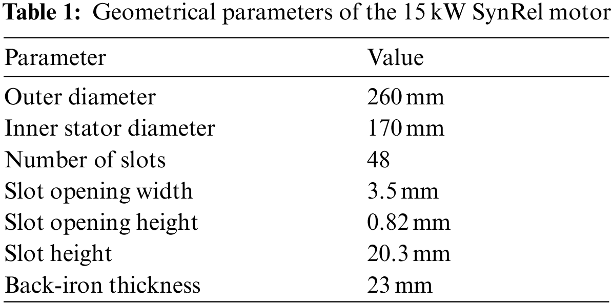
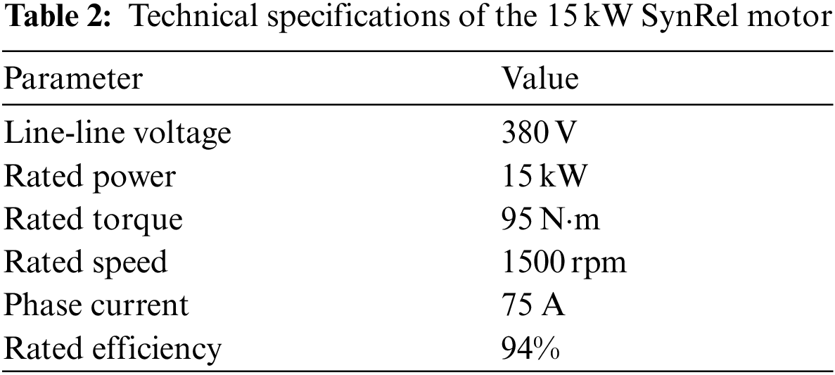
Tabs. 1 and 2 introduce the geometrical parameters and the technical specifications of the proposed 15 kW SynRel motor, respectively.
For analytically analyzing the studied SynRel motor, it firstly starts with the stator magnetic potential which is described as [14]
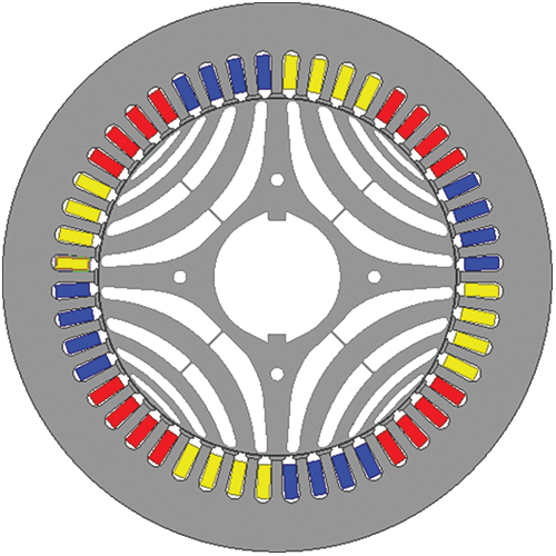
Figure 1: 2D cross section of 15 kW SynRel motor
where Us(θse, t) represents the stator magnetic potential, θse is the electric degree of rotor position on stator reference frame, ωme is the electric angular speed, D is the rotor diameter, p is the pole pair number, αie is the electric current angle, v is a coefficient defined by the Fourier function of Eq. (1), from where v = 2k + 1 (k = 1, 2, 3…), Kv is the coefficient of stator electric loading [15] which is expressed by Eq. (2).
where Ns is the number of windings on one phase, kwv is the distribution factor defined by the physic parameters of the slots and windings, I is the current amplitude given in Tab. 2.
After deriving the stator magnetic potential, it goes to the rotor magnetic potential in order to analytically perform the electrical features of the studied SynRel motor, which is mainly symbolized by the air-gap flux density, the electromagnetic torque, and the electromagnetic force. As it is aforesaid that the rotor geometry of SynRel motor is presenting a rather complex structure for obtaining a higher saliency ratio, bigger electromagnetic torque, and better electrical performance, one pole of the rotor core is sampled and divided into 7 zones based on their magnetic reluctance difference, which is presented in Fig. 2.
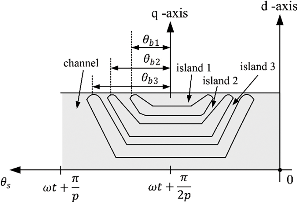
Figure 2: Linearized geometry of one single rotor pole
Then, following each island and channel depicted in Fig. 2, the equivalent magnetic circuit of the studied SynRel motor is drafted as shown in Fig. 3.
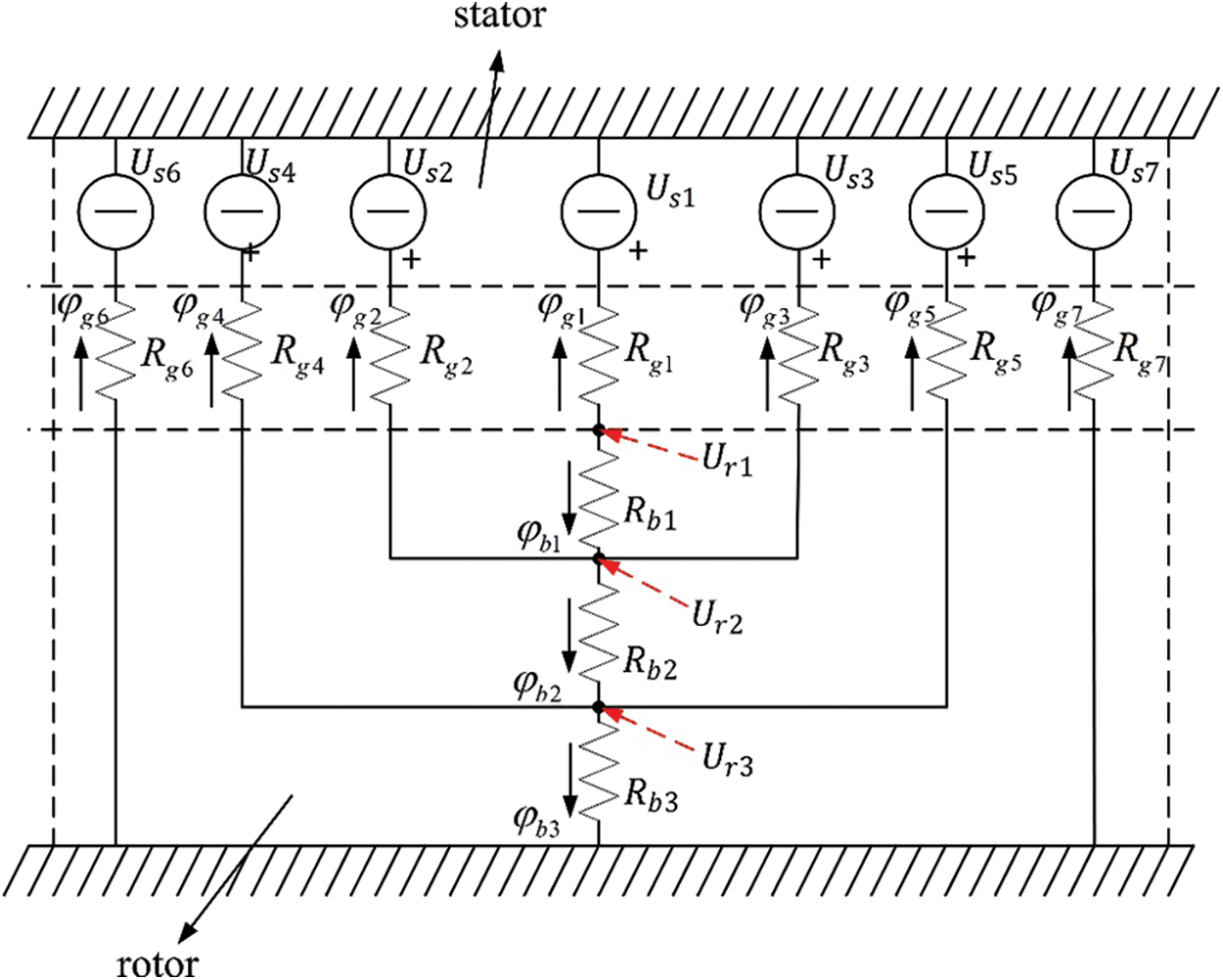
Figure 3: Equivalent magnetic circuit of a rotor pole
From where the rotor magnetic potential of the i-th (i = 1, 2, 3) flux barrier is computed by
where φbi is the flux flowing in each island or channel, Rbi is the equivalent magnetic reluctance.
It is noted from Figs. 2 and 3 that the rotor magnetic potential of 2nd flux barrier includes the effects of 1st flux barrier, while the rotor magnetic potential of 3rd flux barrier is influenced by them from both the 1st and 2nd flux barriers. Therefore, the rotor magnetic potential can be computed starting from the 1st single flux barrier, then, by substituting the rotor magnetic potential of 1st and 2nd flux barrier into the equation of 3rd flux barrier accordingly, the final rotor magnetic potential is resultedin
In Eq. (4), ρ1, ρ2, and ρ3 are the processing coefficient of Ur1, Ur2, and Ur3, respectively, which are cited in [16]. Then, according to Fig. 4, which illustrates the relations between the stator magnetic potential, the rotor magnetic potential, and the air-gap, the air-gap flux density is given by
where Bg(θs) is the air-gap flux density at each circumrenal position on stator reference frame, μ0 is the vacuum relative permeability, and Lg is the air-gap length.
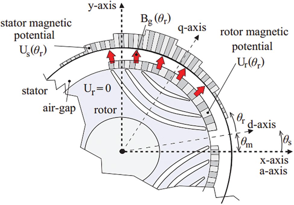
Figure 4: Distribution of the magnetic potentials of stator and rotor
By considering the air-gap length in case of eccentricity, it includes static eccentricity and dynamic eccentricity. To understand the difference between the concentric, static eccentric and dynamic eccentric rotor position, a brief comparison is shown in Fig. 5.
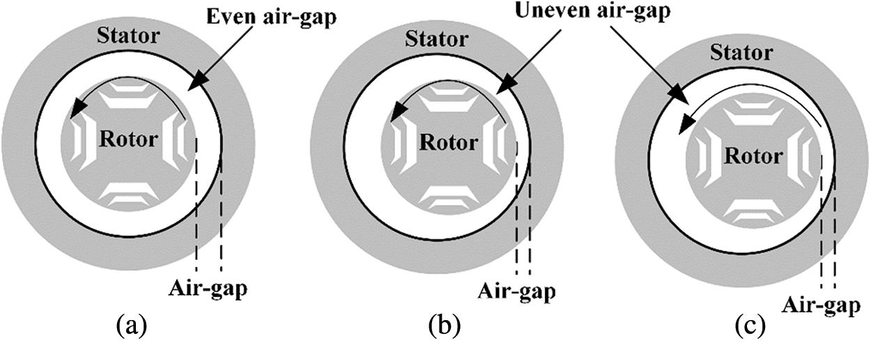
Figure 5: Sketches of the rotor center with respect to the stator center (a) Concentricity (b) Static eccentricity (c) Dynamic eccentricity
As for those two eccentric cases, their equivalent magnetic circuits are accordingly changed due to the uneven air-gap distribution. Fig. 6 presents the diagram of static eccentric SynRel motor that the air-gap length at each position is fixed with rotating rotor, which means the air-gap length is not influenced by the rotor position.
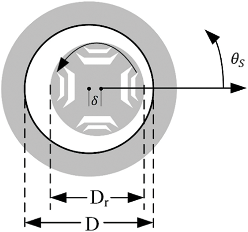
Figure 6: Air-gap length variation with rotor position in case of static eccentricity
In Fig. 6, δ represents the eccentric distance between the stator axial center and the rotor axial center; θs represents the rotating angle of the rotor. Then, according to Fig. 6, the airgap length at each circumferential position based on d-axis is expressed as,
Then, as for the dynamic eccentric SynRel motor, its air-gap length distribution varying on the rotor position is shown in Fig. 7, from where the circumferential air-gap length in case of dynamic eccentricity changes with the rotating rotor.
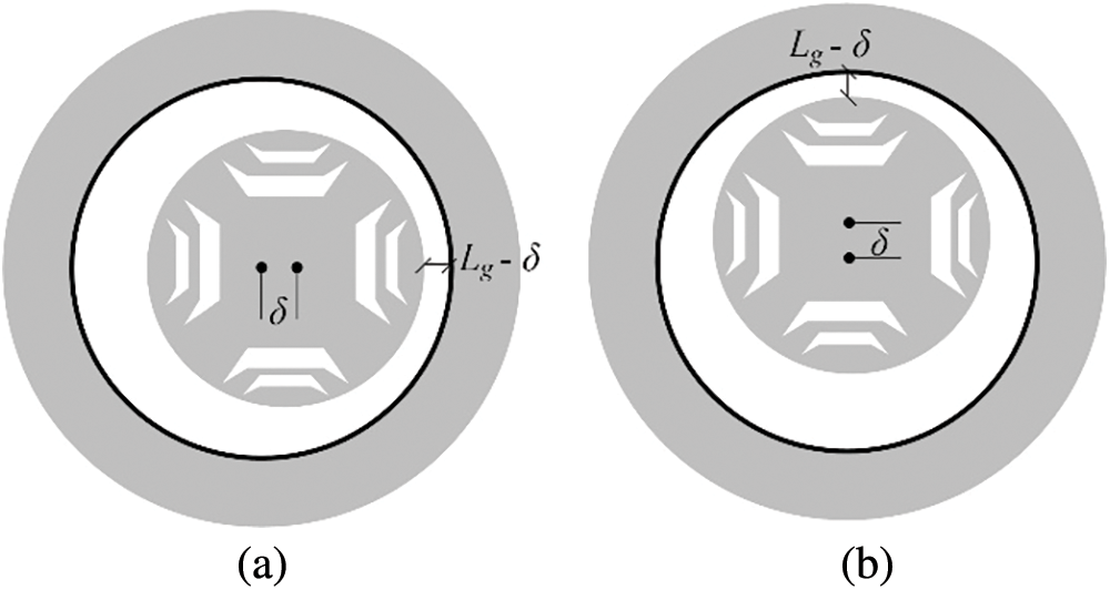
Figure 7: Air-gap length variation with rotor position in case of dynamic eccentricity (a) at θm = 0° (b) at θm = 90°
In Fig. 7a, the shortest air-gap length appears aligning with x-axis, while it aligns with y-axis in Fig. 7b after the rotor rotates 90 mechanical degrees anti-clockwise comparing to Fig. 7a. Hence, the air-gap length variation of dynamic eccentric SynRel motor can be derived as a function of θs in the stator reference frame, which is
2.2 Computation of Air-gap Flux Density
According to eccentric case, by accordingly substituting Eqs. (6) or (7) into Eq. (5), it results in the air-gap flux density distribution under static eccentric case or dynamic eccentric case, respectively.
Also, based on Eqs. (6) and (7), it is noted that the air-gap flux density distribution of static eccentric SynRel motor is the same as it of dynamic eccentric SynRel motor at the initial position, where θm = 0°. Fig. 8 presents the comparison of air-gap flux density distribution of both concentric (healthy), static eccentric and dynamic eccentric SynRel motor at θm = 0° in which both the static eccentricity and dynamic eccentricity are presenting a same rotor positon and air-gap length distribution according to Figs. 5 and 6. Therefore, the air-gap flux density distribution of both static eccentricity and dynamic eccentricity are performing a same waveform. Then, by simulating the concentric case and eccentric cases using electromagnetic finite element tool, Fig. 8 illustrates that the trends of the air-gap flux density distribution are well aligning with each other. However, the amplitude of the air-gap flux density under eccentric case is more fluctuating compared to it under concentric case, which is mainly caused by the inconstant air-gap length variation. By taking rotor position θm = 270° as example, from where the air-gap length of eccentric rotor is closer than designed value, its corresponding air-gap flux density is bigger than usual based on Eq. (8). Similarily, at the rotor position θm = 90°, it presents a totally opposite feature.
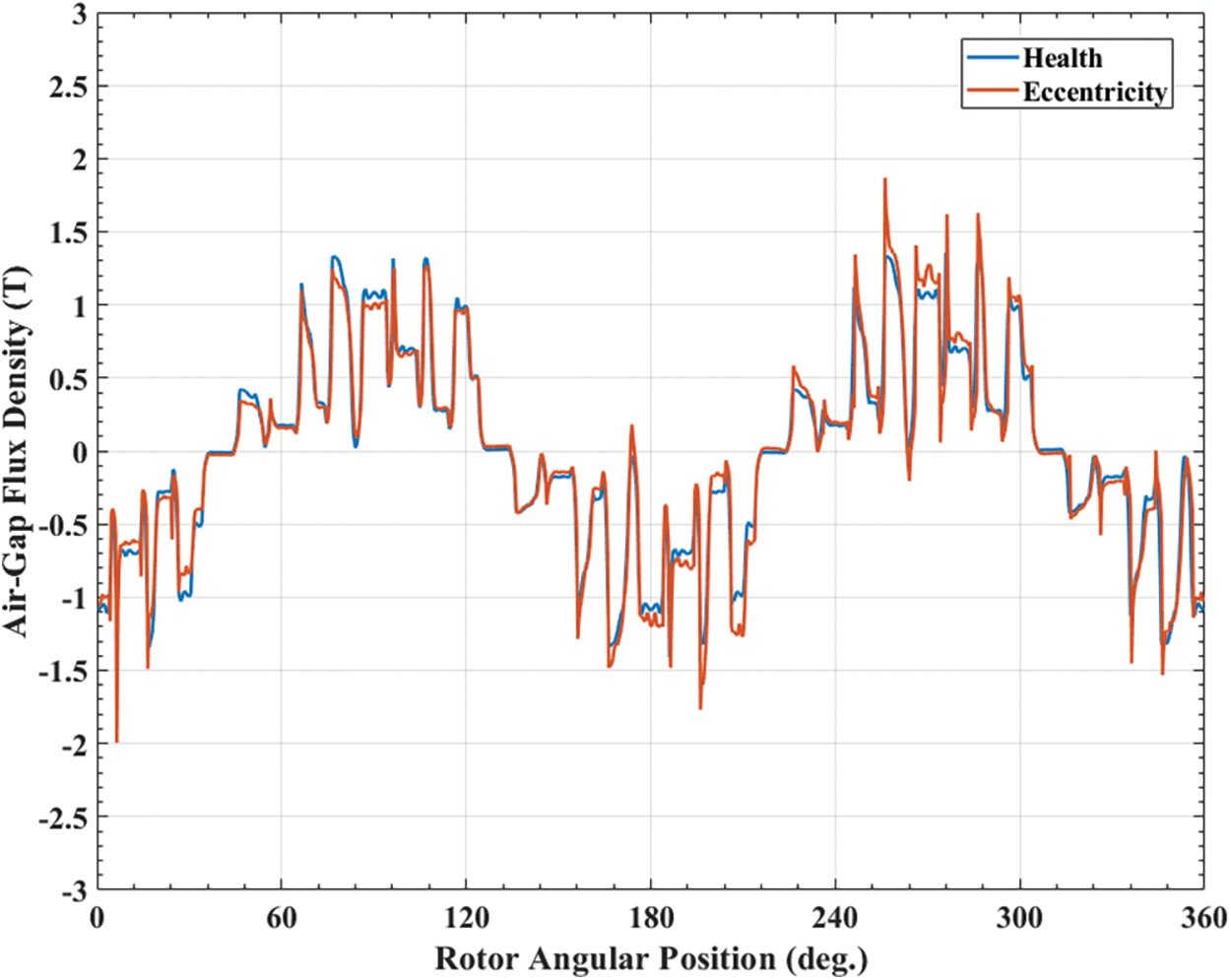
Figure 8: Comparison of the air-gap flux density distribution when θm = 0°
Then, by anticlockwise rotating the concentric, static eccentric, and dynamic eccentric motor, respectively, in 90 mechanical degrees (θm = 90°), which makes Figs. 8 and 9 as shown. The rotor position of static eccentricity and dynamic eccentricity are performed as shown in Fig. 7, that the shortest air-gap length of static eccentricity is still aligning with the x-axis, while the shortest air-gap length of dynamic eccentricity rotates with the rotor, and aligns with the y-axis. Therefore, Fig. 9 presents the air-gap flux densities of concentric, static eccentric and dynamic eccentric rotor, respectively.
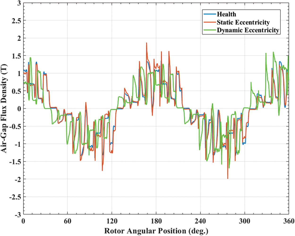
Figure 9: Comparison of the air-gap flux density distribution when θm = 90°
In this case, it describes that the air-gap flux density distributions under both three cases are keeping the same trend. However, the peak values of concentric, static eccentric, and dynamic eccentric case are appearing different amplitudes, respectively. Moreover, the air-gap flux density distribution of both static eccentric and dynamic eccentric SynRel motor are performing an asymmetric distribution.
2.3 Derivation of Electromagnetic Force
Since the electromagnetic force produced in the air-gap plays the main role in the motor vibration, it is critical to investigate the characteristics of the electromagnetic force following the analytical modelling. By using Maxwell Tensor [17], the force density of electromagnetic force can be obtained through
where, σ and τ are representing the electromagnetic force density in radial and tangential direction, respectively, Br and Bθ are representing the air-gap flux density in radial and tangential direction, respectively. Furthermore, as the air-gap flux density in the tangential direction is much smallerwith respect to it in the radial direction [18], therefore, the tangential air-gap flux density is neglected from Eq. (9), which leads the electromagnetic force density to
Due to the symmetric motor geometry, and the number of slots and phases, all the electromagnetic forces acting on the teeth tips are repeating the same as they show on first four teeth tips [19]. Therefore, it is enough to present and analyze the electromagnetic force distribution of the first four teeth tips, as shown in Fig. 10.
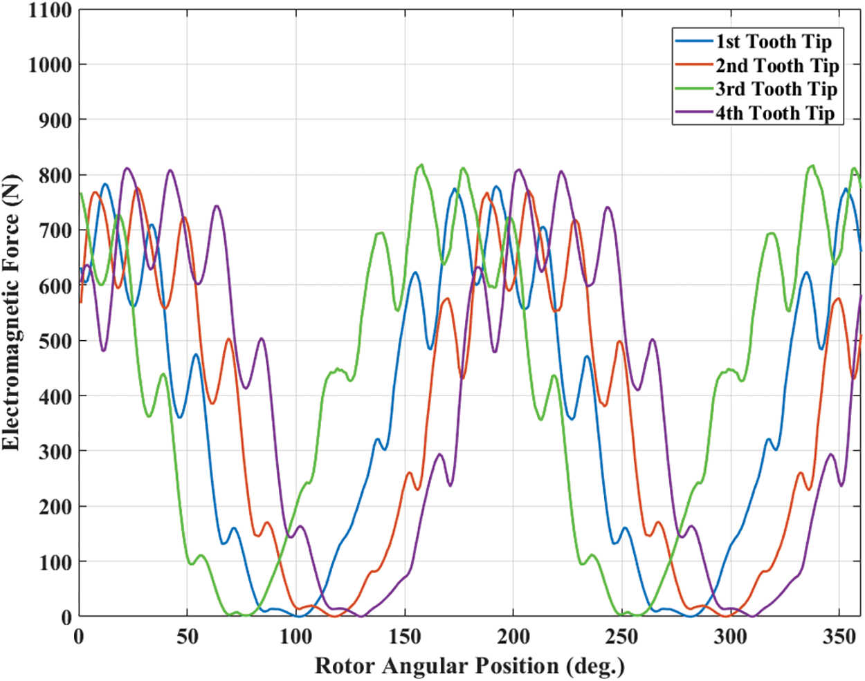
Figure 10: Distribution of electromagnetic force acting on first 4 teeth tips at 1500 rpm
It is illustrated by Fig. 10 that the amplitudes of the electromagnetic force acting on each tooth tip are around 800 N. Besides, their waveforms are performing a similar fluctuating trend. After that, as the armature current is constant, and the magnetic characteristics of the motor under 500 and 1000 rpm conditions are not changing, therefore the distributions of the air-gap flux density and the electromagnetic force under 500 and 1000 rpm are lesser sensitivity to the rotating speed, which means their waveforms are similar to it of under 1500 rpm.
3 Investigation of Vibration of SynRel Motor
As a main part of the vibration investigation, the material applied in the stator core and rotor core is M270-50A of which the properties are listed in Tab. 3.
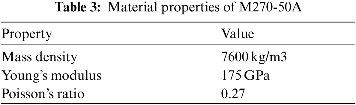
The mass density, Young's modulus, and Poisson's ratio are strongly relating to the mechanical performance of the motor, for instance the modal shape, natural frequency, and vibrational level. For investigating the vibrational level of the motor, it is essential to analyze its modal shape and natural frequency at first.
Modal analysis is the foremost important factor to be considered for exploring the intrinsic structural properties of motor. As for the modal analysis results, the most crucial parts are the modal shape and the natural frequency, which are used for predicting the resonance, evaluating the structural characteristics, investigating the vibration resource, and recognizing the designing error.
There are two methods to perform the modal analysis, which are analytical computation and finite element analysis (FEA). The analytical method is based on Newton's Motion Law as shown in Eq. (11).
where K is the stiffness coefficient matrix, M is the mass matrix, x is the displacement of the motion, ω is the frequency of the motion displacement.
When x = 0, there is no motion displacement, which means no vibration at all. For the other cases, the matrix described in Eq. (11) can be solved as a n-order matrix by using eigenvalues, which deduces the natural frequency and leads Eq. (11) to
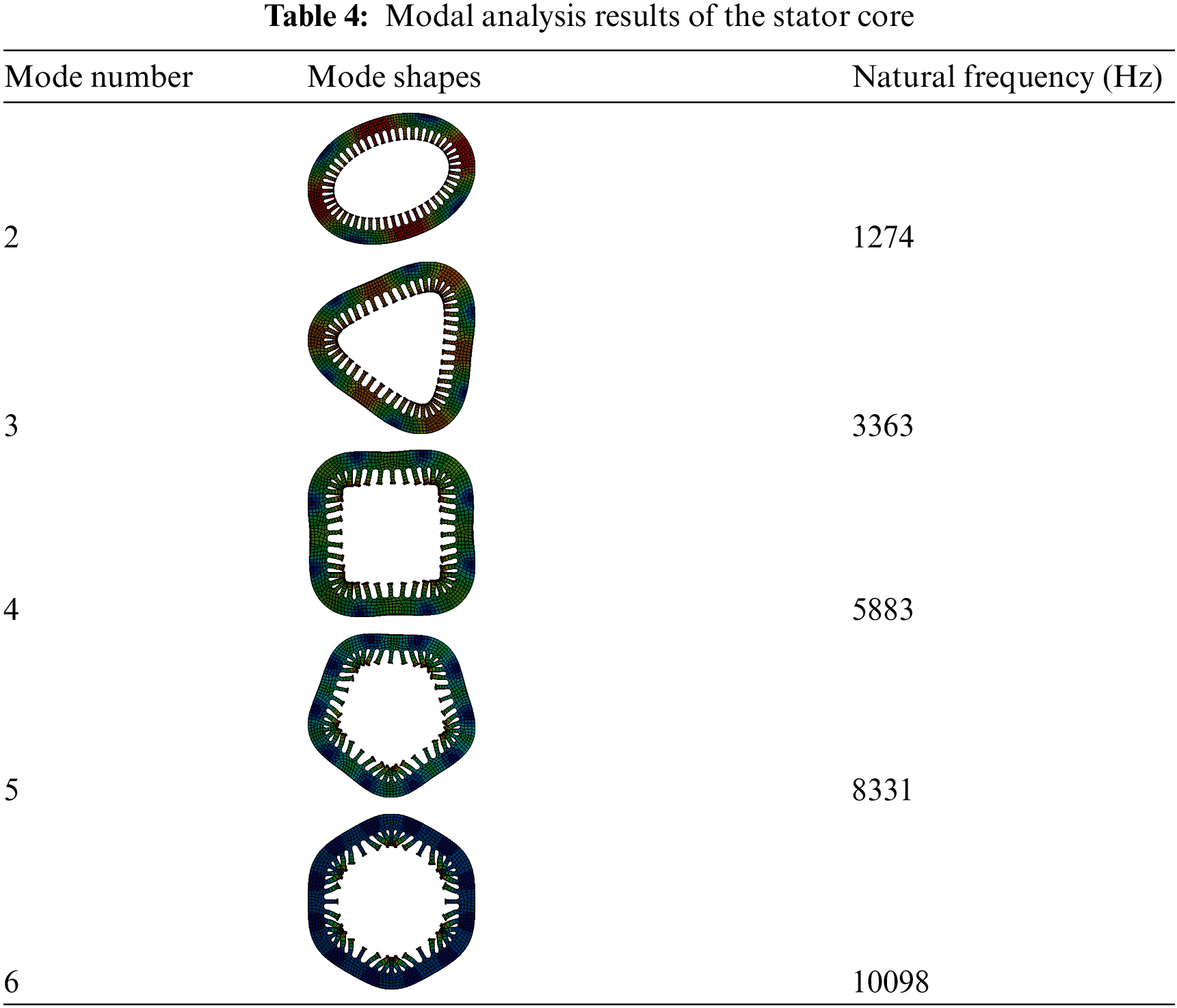
As the structure and the objectives of the SynRel motor is too complex, it is time consuming and lesser accuracy by using analytical method. Therefore, the FEA method is adopted in this paper. Tab. 4 lists and presents the results of modal analysis.
Tab. 4 presents the modal shapes, and their natural frequencies at first six orders. The 1st order natural frequency is very close to it of the 2nd order, which is ignored. From the 3rd order to 6th order, the natural frequency keeps increasing and the structure deforming becomes more obvious.
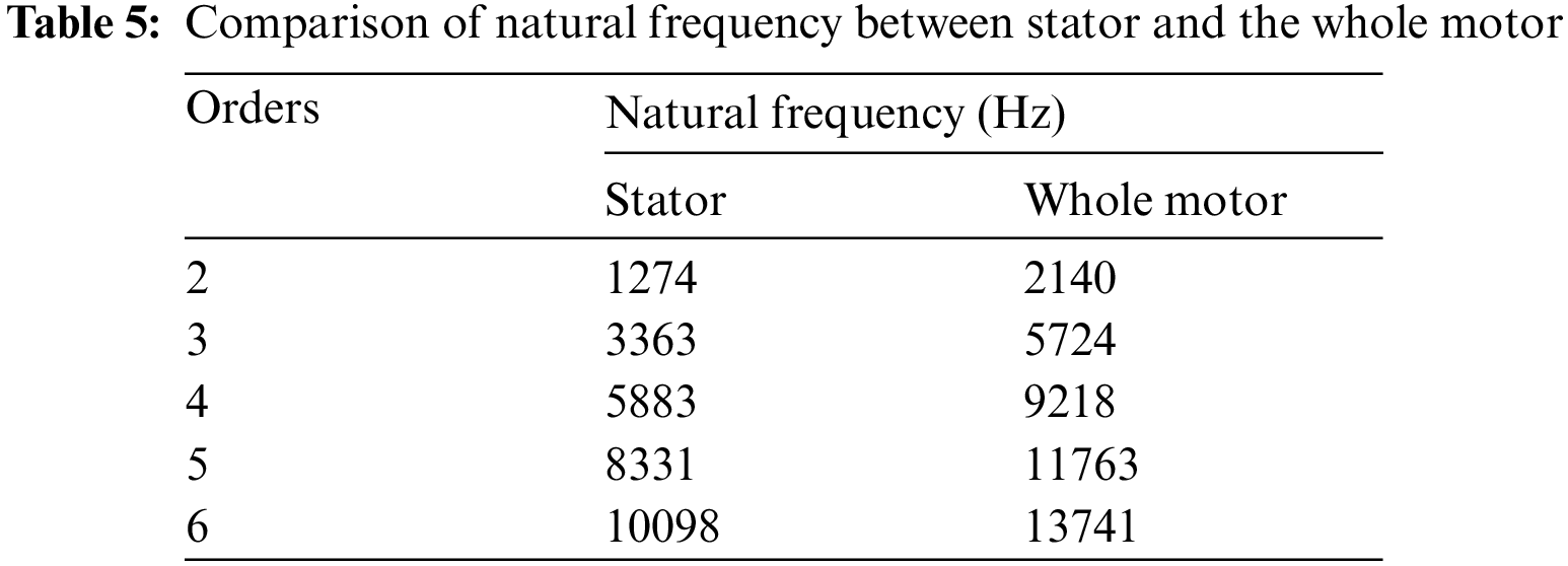
As the mass of the stator occupies a huge proportion of the whole motor, it is meaningful to separately analyze the modal shape and natural frequency of single stator. Then, Tab. 5 compares the natural frequency of the stator to it of the whole motor.
By setting the eccentric error as 0.15 mm for all the eccentric cases and applying the electromagnetic force onto the housing of the motor, a harmonic response analysis is conducted in this section to investigate the vibrational level of the studied SynRel motor in cases of concentricity, static eccentricity, and dynamic eccentricity, which is shown in Fig. 11 (g = 9.8 m/s2).
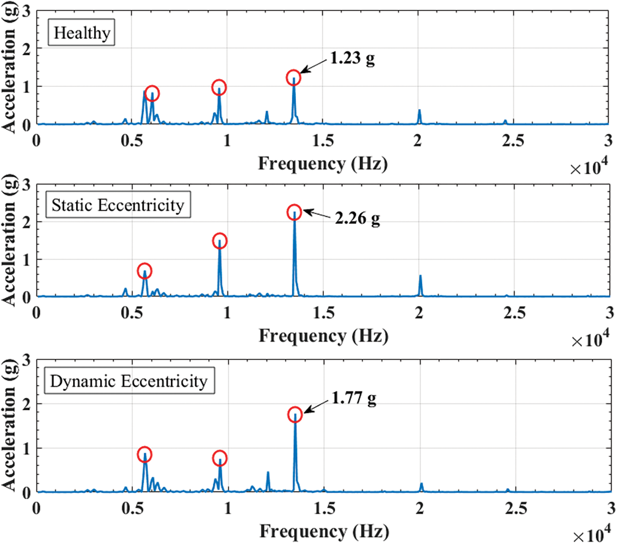
Figure 11: Comparison on vibration level of SynRel motor
Due to the uneven distribution of air-gap length in case of static eccentricity, dynamic eccentricity and concentricity, their air-gap flux densities are performing different waveforms with varying amplitudes and trends. Therefore, their radial air-gap flux densities and tangential air-gap flux densities are changing according to the air-gap flux density at each position. Consequently, the electromagnetic force in each eccentric case presents different amplitude, respectively, therefore the corresponding vibration level achieves different amplitude.
From Fig. 11, it is illustrated that the peak vibrations are occurred around 13500 Hz, which is a natural frequency. Among these three cases, the peak vibration of static eccentricity is the highest, which is at 2.26 g, whilst the peak vibration of concentricity and dynamic eccentricity are at 1.23 and 1.77 g, respectively. Hence, the peak vibration of static eccentric case is 83.74% higher than health motor, and the peak vibration of dynamic eccentric case is 43.9% higher than health motor. Also, it can also be validated by the electromagnetic force distribution, that the static eccentric motor produces bigger and more fluctuant electromagnetic forces. Furthermore, the vibration analysis provides a possible solution for identifying the eccentric status of the manufactured SynRel motors.
In this section, the proposed analytical model and the vibrational analyzing method are validated by a prototype test. The protype of the studied SynRel motor is manufactured for characterizing and testing its operation, which intends to get the motor performance when driven by a commercial driver, but mainly focuses on the vibration characteristics under various operating conditions. The test specifications and the needed equipment are presented in Figs. 12 and 13, which introduces the test bench and vibrating sensor.
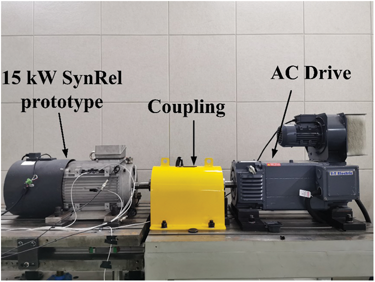
Figure 12: Test bench and the SynRel prototype motor
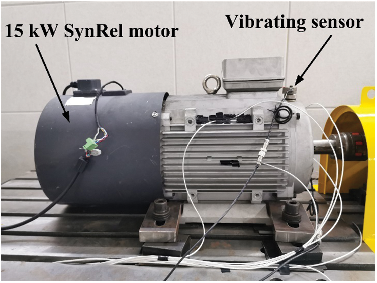
Figure 13: Connections of vibration test
By running the prototype under 15 kW condition, it is tested on various speed. The housing acceleration is taken as the symbol of the vibration level. Tab. 6 presents the experimental results.
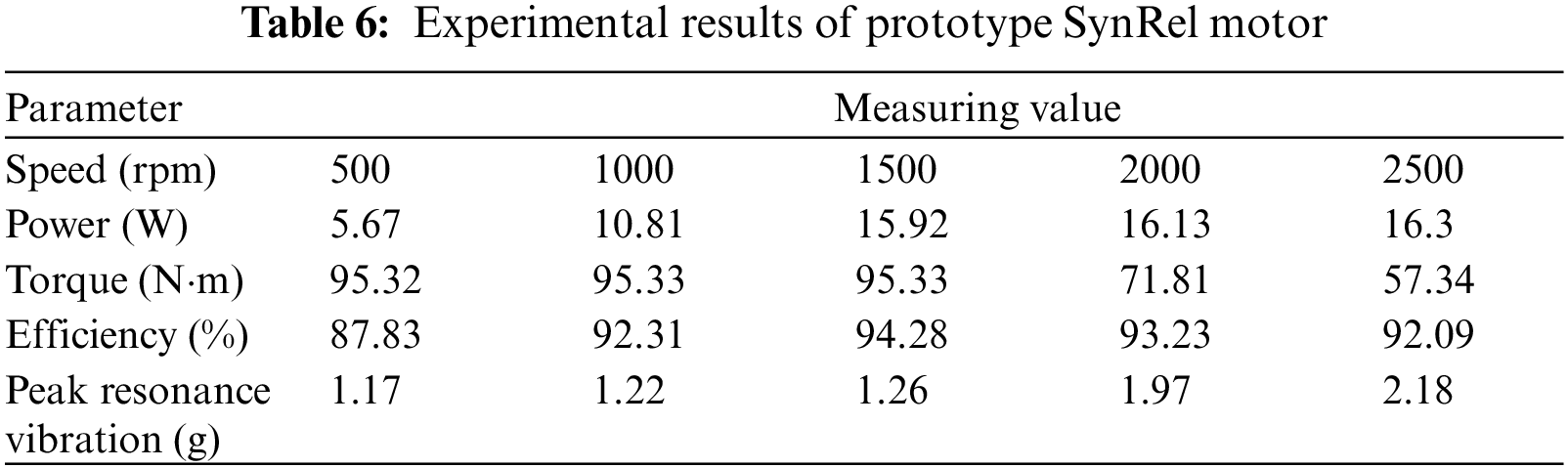
The peak resonance vibration under 1500 rpm is 0.03 g higher than the FEA result. However, the tested power, torque, and efficiency are both higher than the designed value listed in Tabs. 1 and 2, therefore, it is reasonable there is more vibration with respect to the FEA results. Hence, it is validated by Tab. 6 that the proposed model is effective, and the analyzing method is feasible, which can be used for further analysis and study.
5 Neural Network for Monitoring Eccentricity
During the daily usage of the SynRel motor, it is nearly impossible to monitor the eccentric error at full-time range manually. Hence, a neural network model is developed in this section to realize the function that automatically monitoring and reporting the eccentric error by using artificial intelligence [20]. Fig. 14 shows the multilayer feed-forward artificial neural network with one hidden layer [21].
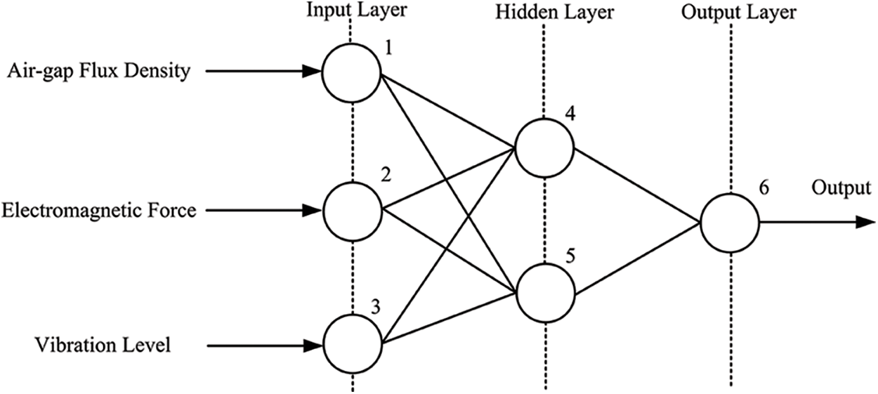
Figure 14: Multilayer feed-forward artificial neural network
There are three inputs with this neural network, which are the air-gap flux density distribution, the electromagnetic force waveform, and the vibration level, as three nodes on the input layer [22]. Besides, they are denoted by x1, x2, and x3, respectively. One hidden layer is utilized to perform the processing, which is with any number of possible nodes [23]. Finally, the output layer has only one output, which is the eccentric displacement between the real rotor center and the rotating center of the SynRel motor. The output is denoted by w1.
Then, the activation of a neuron i in the layer k, is defined as
where, fs is the sigmoid function, that is fs(x) = 1/(1 + e−x). Besides, uik is defined by
In this case, the backpropagation learning algorithm is utilized for training the neural networks [24,25], which is employed to use the gradient descent algorithm to estimate the interconnected weights [26,27]. Then, the connected weights are varying by
From where it meets with
where y is target value, and ε is smaller integer.
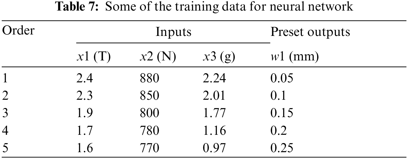
The proposed neural network is learning the training data generated from FEA simulation, including the air-gap flux density distribution, electromagnetic force waveform, and vibration level, in case of static eccentric and dynamic eccentric SynRel motor. Some of the training data are collected and presented in Tab. 7 for a generic approach to the neural network training.
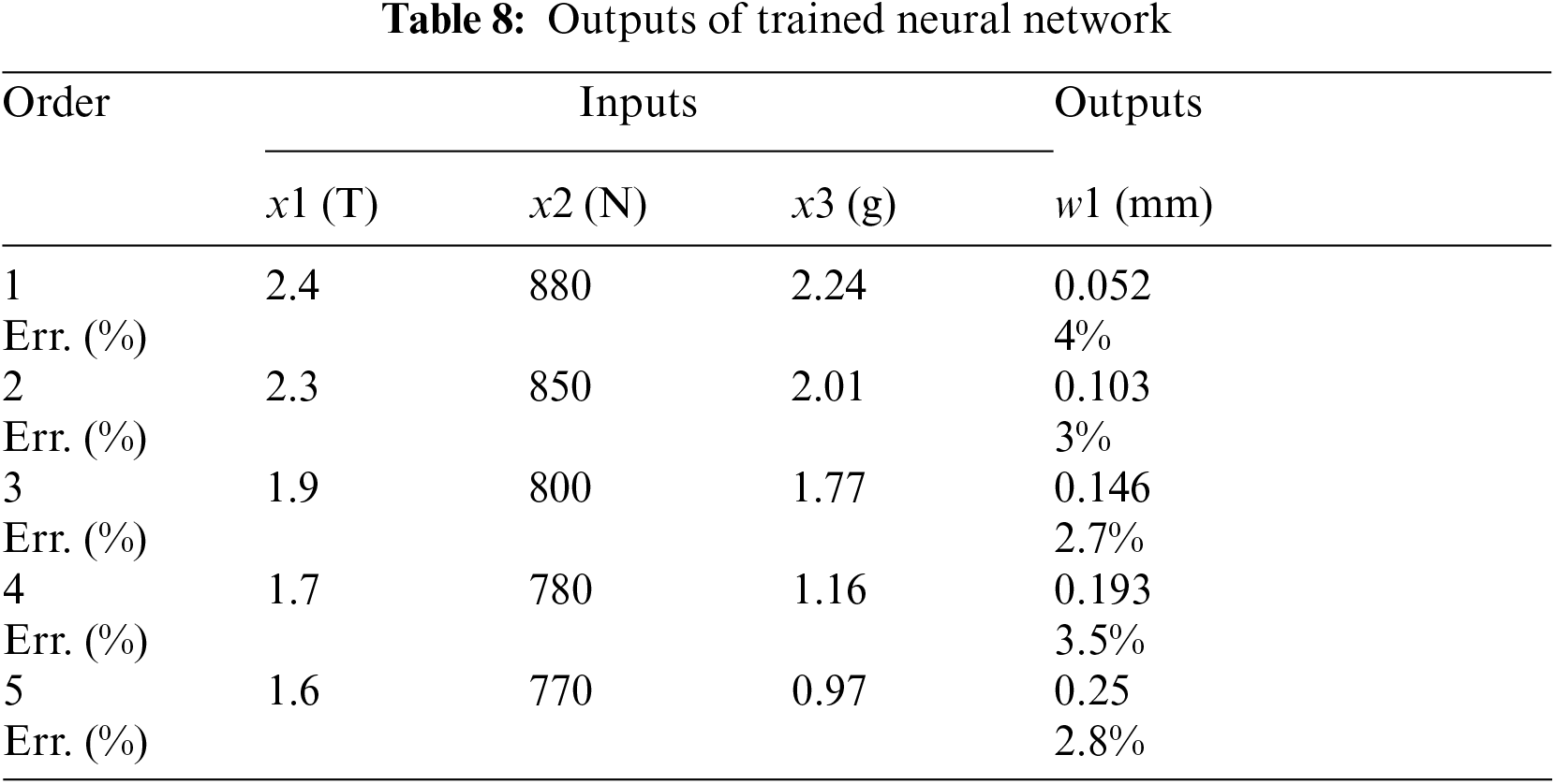
At the beginning of the training process, the connection weights are assigned as a random value. Then, by generating more training data through FEA simulation, the proposed neural network continues learning till the learning error smaller than 5%. In Tab. 8, it presents the outputs of trained neural network.
In this paper, a 15 kW SynRel motor is designed as a case study for its vibration test. Firstly, the analytical model of the studied SynRel motor is developed to compute the key parameters, such as the magnetic potentials, air-gap flux density and electromagnetic force density. Then, the modal analysis is conducted to realize the mechanical characteristics of the studied SynRel motor, followed by a harmonic response FEA simulation for investigating the vibration features. After that, a protype test is performed to prove the developed analytical model and the determined analyzing method. Finally, a neural network focusing on the eccentric error prediction is proposed.
From the results, it proves that the novel neural network is predicting the eccentric error efficiently and accurately, by which it is possible to artificially monitor the eccentric error of the SynRel motor at full-time range. However, from the obtained results so far, it is still challenging to recognize and distinguish the type of eccentricity, including the static and dynamic eccentricity.
Acknowledgement: Many appreciations go to the colleagues who contributed to this paper's work but not mentioned, and genuinely grateful to all the authors of the references for their valuable investigations and contributions.
Funding Statement: The authors received no specific funding for this study.
Conflicts of Interest: The authors declare that they have no conflicts of interest to report regarding the present study.
1. S. Taghavi, “Design of synchronous reluctance machines for automotive applications,” Ph. D. Dissertation, Concordia University, Canada, 2015. [Google Scholar]
2. M. Ehsani, Y. Gao, S. E. Gay and A. Emadi, Modern electric, hybrid Electric, and fuel cell vehicles, vol. 1. United States: CRC Press, pp. 10–14, 2005. [Google Scholar]
3. H. Mahmoud, “Synchronous reluctance machine: Eccentricity analysis and design criteria,” Ph. D. Dissertation, University of Padova, Italy, 2017. [Google Scholar]
4. R. R. Moghaddam, “Synchronous reluctance machine (SynRM) in variable speed drives applications,” Ph. D. Dissertation, Sweden, 2011. [Google Scholar]
5. T. Matsuo and T. Lipo, “Rotor design optimization of synchronous reluctance machine,” IEEE Transactions on Energy Conversion, vol. 9, no. 2, pp. 359–365, 1994. [Google Scholar]
6. L. Yang, J. Li, R. Qu, D. Ye, H. Lu et al., “Electromagnetic force and vibration analysis of permanent-magnet-assisted synchronous reluctance machines,” IEEE Transactions on Industry Applications, vol. 54, no. 5, pp. 4246–4256, 2018. [Google Scholar]
7. Y. Xu, H. Fang, D. Li, R. Qu and J. Guo, “Fast evaluation of high frequency electromagnetic force and vibration for PMSMS based on field reconstruction technique,” IEEE Transactions on Industry Applications, vol. 56, no. 4, pp. 3549–3548, 2020. [Google Scholar]
8. J. Li, H. Mahmoud, M. Degano, C. Gerada, A. Bardalai et al., “Impact of vibration of eccentric permanent magnet assisted synchronous reluctance machine,” in 2020 XXVI Int. Conf. on Electrical Machines (ICEM), Gothenburg, 2020. [Google Scholar]
9. J. Li, H. Mahmoud, M. Degano and C. Gerada, “Vibration analysis of permanent-magnet-assisted synchronous reluctance machines,” in 2019 22nd Int. Conf. on Electrical Machines and Systems (ICEMS), Harbin, 2019. [Google Scholar]
10. N. Bianchi, M. Degano and E. Fornasiero, “Sensitivity analysis of torque ripple reduction of synchronous reluctance and interior PM motors,” IEEE Transactions on Industry Applications, vol. 51, no. 1, pp. 187–195, 2015. [Google Scholar]
11. N. Bianchi, H. Mahmoud, and S. Bolognani, “Fast synthesis of permanent magnet assisted synchronous reluctance motors,” IET Electric Power Applications, vol. 10, no. 5, pp. 312–318, 2016. [Google Scholar]
12. H. Mahmoud, N. Bianchi, M. Degano, M. Al-ani and C. Gerada, “Eccentric reluctance and permanent magnet synchronous machines comparison,” IEEE Transactions on Industry Applications, vol. 54, no. 6, pp. 5760–5771, 2018. [Google Scholar]
13. G. Pellegrino, T. M. Jahns, N. Bianchi, W. L. Soong and F. Cupertino, The rediscovery of synchronous reluctance and ferrite permanent magnet motors: Tutorial course notes, Germany: Springer Press, pp. 43–47, 2016. [Google Scholar]
14. H. Mahmoud and N. Bianchi, “Nonlinear analytical model of eccentric synchronous reluctance machines considering the iron saturation and slotting effect,” IEEE Transactions on Industry Applications, vol. 53, no. 3, pp. 2007–2015, 2017. [Google Scholar]
15. S. S. R. Bonthu, A. Arafat and S. Choi, “Comparisons of rare earth and rare earth free external rotor permanent magnet assisted synchronous reluctance motors,” IEEE Transactions on Industrial Electronics, vol. 64, no. 12, pp. 9729–9738, 2017. [Google Scholar]
16. J. Li, “Vibration analysis and investigation of synchronous reluctance motor,” Ph. D. Dissertation, University of Nottingham, U.K., 2021. [Google Scholar]
17. M. Gamba, G. Pellegrino, and F. Cupertino, “Optimal number of rotor parameters for the automatic design of synchronous reluctance machines,” in Int. Conf. on Electrical Machines (ICEM), Berlin, pp. 1334–1340, 2014. [Google Scholar]
18. H. Mahmoud and N. Bianchi, “Eccentricity in synchronous reluctance motors—part I: Analytical and finite-element models,” IEEE Transactions on Energy Conversion, vol. 30, no. 2, pp. 745–753, 2015. [Google Scholar]
19. N. Bianchi, H. Mahmoud and S. Bolognani, “Fast synthesis of permanent magnet assisted synchronous reluctance motors.” IET Electric Power Applications, vol. 10, no. 5, pp. 312–318, 2016. [Google Scholar]
20. A. Alhussain, H. Kurdi and L. Altoaimy, “A neural network-based trust management system for edge devices in peer-to-peer networks,” Computers, Materials & Continua, vol. 59, no. 3, pp. 805–815, 2019. [Google Scholar]
21. A. Maamar and K. Benahmed, “A hybrid model for anomalies detection in ami system combining k-means clustering and deep neural network,” Computers, Materials & Continua, vol. 60, no. 1, pp. 15–40, 2019. [Google Scholar]
22. B. Gu, W. Xiong and Z. Bai, “Human action recognition based on supervised class-specific dictionary learning with deep convolutional neural network features,” Computers, Materials & Continua, vol. 63, no. 1, pp. 243–262, 2020. [Google Scholar]
23. C. Shen, Y. Chen, B. Chen and J. Xie, “A compensation controller based on a nonlinear wavelet neural network for continuous material processing operations,” Computers, Materials & Continua, vol. 61, no. 1, pp. 379–397, 2019. [Google Scholar]
24. P. J. Werbos, “Backpropagation through time: What it does and how to do it,” Proc. of IEEE: Special Issue on Neural Network, vol. 78, no. 5, pp. 124–135, 1992. [Google Scholar]
25. J. Oda, T. Mizukami and A. Wang, “Design of adaptive structure using neural network,” Transactions of the Japan Society of Mechanical Engineerings (A), vol. 58, no. 4, pp. 45–52, 1992. [Google Scholar]
26. Z. Li, W. Li, F. Lin, Y. Sun, M. Yang et al., “Hybrid malware detection approach with feedback-directed machine learning,” Science China Information Sciences, vol. 63, no. 3, pp. 39–45, 2020. [Google Scholar]
27. Z. Li, B. Chang, S. Wang, A. Liu, F. Zeng et al., “Dynamic compressive wide-band spectrum sensing based on channel energy reconstruction in cognitive internet of things,” IEEE Transactions on Industrial Informatics, vol. 14, no. 6, pp. 2598–2607, 2018. [Google Scholar]
 | This work is licensed under a Creative Commons Attribution 4.0 International License, which permits unrestricted use, distribution, and reproduction in any medium, provided the original work is properly cited. |