DOI:10.32604/cmc.2022.024782
| Computers, Materials & Continua DOI:10.32604/cmc.2022.024782 | |
| Article |
Directional Wideband Wearable Antenna with Circular Parasitic Element for Microwave Imaging Applications
1Faculty of Electronic and Computer Engineering (FKEKK), Universiti Teknikal Malaysia Melaka (UTeM), Durian Tunggal, 76100, Melaka, Malaysia
2Electrical Engineering Department, Jouf University, Sakaka, 72388, Aljouf, Kingdom of Saudi Arabia
3Faculty of Engineering, Universiti Malaysia Sabah (UMS), Kota Kinabalu, 88400, Sabah, Malaysia
4Centre for Wireless Communications (CWC), University of Oulu, Oulu, 90014, Finland
5Advanced Communication Engineering (ACE) CoE, Faculty of Electronic Engineering Technology, Universiti Malaysia Perlis (UniMAP), Arau, 02600, Perlis, Malaysia
*Corresponding Author: Z. Zakaria. Email: zahriladha@utem.edu.my
Received: 31 October 2021; Accepted: 21 December 2021
Abstract: This work proposes a wideband and unidirectional antenna consisting of dual layer of coplanar waveguide based on the circular parasitic element technique. The design procedure is implemented in three stages: Design A, which operates at 3.94 GHz with a bandwidth of 3.83 GHz and a fractional bandwidth (FBW) of 97.2%; Design B, which operates at 3.98 GHz with a bandwidth of 0.66 GHz (FBW of 56.53%); and Design C as the final antenna. The final Design C is designed to resonate at several frequencies between 2.89 and 7.0 GHz for microwave imaging applications with a bandwidth of 4.11 GHz (79.8%) centered at 5.15 GHz. This antenna is fabricated fully using two textile materials: felt as the substrate and ShieldIt as the conductor. It features a unidirectional radiation with a gain of 5.5 dBi, and reduced low back radiation from 2.06 to−7.81 dB. The front-to-back ratio (FBR) for Design A, Design B and Design C are 4.82, 2.94 and 11.36 dB, respectively. This antenna is wideband with unidirectional radiation, lightweight, and flexible.
Keywords: Wearable antennas; ultrawideband antennas; unidirectionalantennas; microwave imaging
A report released by the National Breast Cancer Foundation in 2015 indicated that breast cancer is one of the significant causes of female death worldwide [1]. Researchers are intensively exploring different approaches aimed at early breast tumor detection, considering the limited access to clinical imaging [2,3]. Wearable antennas are electronic-based devices that can be worn regularly, integrated into clothing, or attached to the human body for this purpose. However, designing such antennas is particularly challenging, as their performance is highly influenced by the electromagnetic interaction with the body itself [4].
Generally, several procedures can be used for cancer screening, such as X-ray scanning, magnetic resonance imaging, biopsy, and bronchoscopy screening. However, these technologies may cause mental trauma in patients and produce harmful ionizing rays when frequently used [2,3]. Moreover, these equipment needs to be operated by trained physicians and incur high maintenance costs. Besides that, these technologies also suffer from inaccuracies, with false-positive rates of between 60% and 70%. Furthermore, approximately 20% to 30% of breast cancer is undetected by mammography [2–5], the most widely used screening method for breast cancer. An alternative method to detect early-stage breast cancer is the microwave imaging technique (MWI). Such a method is appealing due to its low procurement cost, ease of operation, non-invasive nature, mobility, and efficiency in localizing and detecting these tumours [6–10].
One of the important components in the microwave imaging method is the antennas. In recent years, several techniques have been applied to microwave breast imaging using different antennas. Antennas operating at low-frequency bands offer good penetration, whereas those operating at high-frequency bands offer good resolution [11]. An example in [12] used a Vivaldi antenna to enable a high gain and wide bandwidth. These properties were achieved simultaneously by increasing the number of corrugations and the antenna length. Another antipodal Vivaldi antenna design was presented in [13], with an ultrawide bandwidth from 1.3 to 20 GHz (175%) using a fern fractal leaf structure. It also produced a high directive gain of 10 dBi, and a fidelity factor above 90%. Besides Vivaldi antennas, a square monopole antenna was used for MWI due to its wide bandwidth and ease of fabrication [14]. On the other hand, authors in [15] integrated slots into the antenna ground plane to provide a wide operating frequency range. Besides that, the monopole antenna proposed in [16] embedded L-shaped slits into the ground plane for bandwidth enhancement. In improving radiation efficiency, two-slot geometries (T-shaped slots and E-shaped strips) were inserted in the ground plane to improve radiation efficiency to 86% over a large bandwidth [17]. Similarly, an ultra-wideband monopole antenna with a modified octagonal-shaped patch was introduced in [18] to enhance the radiation efficiency while operating over a wide frequency range.
Planar monopole antennas generally offer wide operating bandwidth, ease of fabrication, low cost, compact size, and light weight [19–25]. However, they tend to produce bidirectional radiation characteristics [26]. The unidirectional characteristic of antennas is crucial in MWI despite increasing the complexity of antenna design, as bidirectional antennas increase the possibility of environmental interference and false detections at the receiver terminals when used for MWI [27]. To improve the directional properties in conventional planar monopoles, several techniques have been proposed, including incorporating reflecting elements, adding cavities or shielding planes behind the main radiator, and using absorbent materials. However, these approaches tend to increase antenna size and design complexity while affecting antenna efficiency [26].
An example of modifying the bidirectional to unidirectional radiation for such antennas is presented in [28]. The radiating fins of a side-slotted Vivaldi antenna (SSVA) were modified by etching six slots on its sides to produce directive radiation with high gain. Besides that, horns are also another good alternative with satisfactory efficiency, gain, and directivity for MWI [29]. In [30,31], a simple directional monopole antenna is designed on a high-permittivity material for breast imaging, with the use of a reflector that provides directional radiation patterns. Finally, in [32], an open cavity was inserted on the reverse side of the antenna to improve unidirectional broadside radiation and maintain UWB impedance bandwidth.
Flexibility feature of MWI devices is another important factor to be considered. In [33], a 16-element antenna array operating with single and dual-polarization in the shape of a breast is proposed. The reflector element is placed at 1 cm distance from the antenna to improve its directivity. However, such distance between the reflector and the antenna is difficult to be accepted due to the need for large spacing. On the other hand, a flexible CPW-fed UWB antenna was proposed in [34]. Fractal topology is integrated into the antenna to enable high directivity and gain, resulting in a more complex antenna design. Meanwhile, the proposed antenna in [35] with a centred rectangular slot and staircase-shaped slots resulted in a wide bandwidth, directional behavior and compact size. However, its bandwidth is limited to 67%. All antennas from [33–35] are flexible antennas, as they are made using Kapton polyimide substrate and are inkjet-printed. However, these works are not focused on improving the directivity or FBR. Furthermore, a single-layered Kapton is very thin (t = 0.12 mm) and can be more costly compared to other flexible materials such as textiles.
In this study, a simple, compact and dual-layered monopole antenna with a circular parasitic element is proposed. This, in combination with its coplanar waveguide (CPW) feedline, enabled the antenna to achieve a wide operating bandwidth with unidirectional radiation. The main patch is fed by a 50 Ω CPW line, with the rear reflector grounded. In between them, a circular parasitic element is integrated on a separate layer to improve directivity. It is directly attached to the ground plane to maintain compactness. This resulted in a satisfactory tradeoff between the antenna size and directivity in comparison to existing literature. Despite its slightly larger size due to the low dielectric properties of the textile substrate, the choice of felt substrate ensured cost-effectiveness and is more user friendly for breast tumour detection due to its clothing-like structure. Simulation and measurement results indicated a good agreement, with the proposed antenna operating from 2.89 GHz to 7.00 GHz (79.8% of bandwidth), a stable unidirectional radiation pattern, improved directivity, and low front-to-back ratio (FBR) of 11.36 dB.
The antenna design procedure will be described in the next section presents the full design of the proposed antenna, followed by the simulation results, parametric study, and experimental observations. Finally, our concluding remarks are provided in the last section.
Fig. 1 shows the schematic layout of the proposed wideband wearable antenna with a circular parasitic element. It is simulated using CST Microwave Studio [36] and is designed using felt as its substrate (with a dielectric constant, εr = 1.45; and a tangent loss, tanδ = 0.045) and ShieldIt SuperTM to form its conductors (with an estimated conductivity of 6.67 x 10⁵ S/m). The antenna consists of five layers: two substrate layers and three-conductor layers.
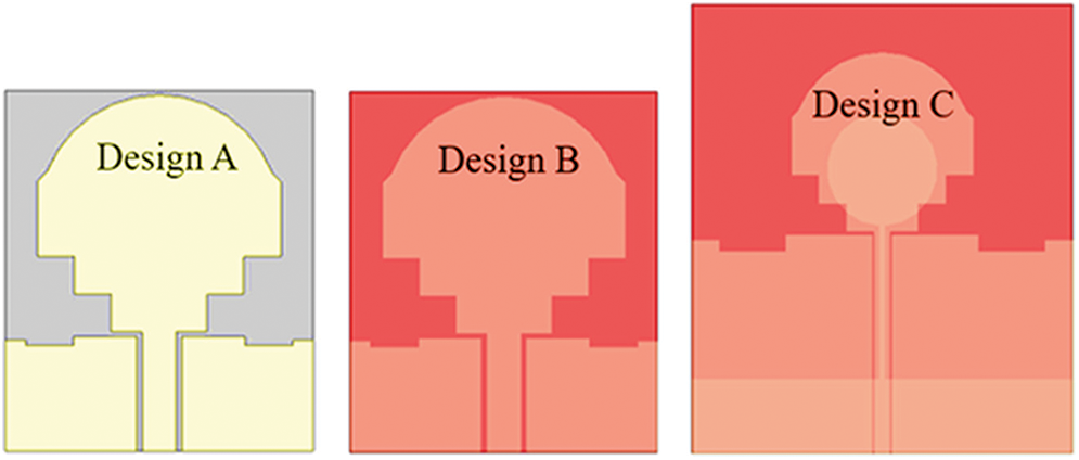
Figure 1: Development steps of the proposed antenna–Design A, Design B and Design C
The antenna design process consists of three main stages, as illustrated in Fig. 1 (from Design A to Design C). The top layer consists of the main patch and a CPW feedline. For the first stage, a basic rectangular patch is designed as the main radiator on the top layer of Design A. Next, the top of this rectangular radiator is rounded, which improves the FBR in the antenna's radiation pattern [37]. Besides that, staircase-shaped steps are added to the bottom section of the main patch. This technique improved the impedance matching of the antenna over a wide frequency range [38]. This is followed by the modification of the CPW ground plane, also using steps to enable the antenna's UWB operation [39]. For the second stage (Design B), a layer of the conductor is added behind the antenna, with the same dimension as substrate layer 1 (please see Fig. 2). The purpose of this addition is to enable the antenna to radiate towards the forward direction.

Figure 2: Proposed wideband wearable antenna (Design C), (a) Top view of substrate layer 1, (b) Top view of substrate layer 2, (c) Rear view of substrate layer 2, (d) Side view
In the third stage, the patch from Antenna B is modified to enable size reduction, resulting in Design C, as presented in Fig. 2. The co-planar waveguide is optimized to improve the bandwidth of the antenna when a circular parasitic patch and a microstrip line is integrated onto the next felt layer (substrate layer 1). The addition of the circular parasitic patch improved the forward directivity of the antenna, similar to [40]. Finally, a full ground plane is integrated at the bottom-most layer of this antenna formed using ShieldIt SuperTM.
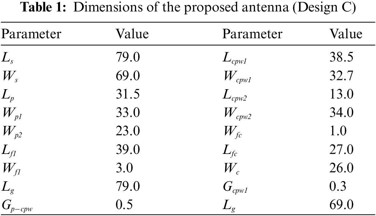
The overall antenna (and substrate) size is dimensioned at 79 mm (substrate length, Ls) × 69 mm (substrate width, Ws). The CPW line feeding the main patch is sized at 39 mm (length, Lf1) × 3.0 mm (width, Wf1), and is terminated with a SubMiniature version A (SMA) connector. On the other hand, the rectangular section of the parasitic patch located on substrate layer 2 is dimensioned at 69.0 mm (length, Lcpw2) × 13.0 mm (width, Wcpw2), whereas the feedline connecting this patch to the circular patch is 27.0 mm (length, Lfc) × 0.5 mm (width, Wfc). The diameter of the circular patch, Wc = 26.0 mm. All antenna dimensions are summarized in Tab. 1.
The reflection coefficients and resonant frequencies of the proposed antenna at different stages: Design A, Design B, and Design C are presented in Fig. 3 and summarized in Tab. 2. The variation in the operating frequency for each design stage is mainly due to the difference in geometry. Design A operates with a wide 3.83 GHz bandwidth (97.2% of fractional bandwidth, FBW). It should be noted that this design does not incorporate any rear ground plane on the reverse side of the substrate and is made using a single substrate layer. The bandwidth enhancement is due to the CPW located at the patch.

Figure 3: Simulated reflection coefficients for Design A, Design B and Design C
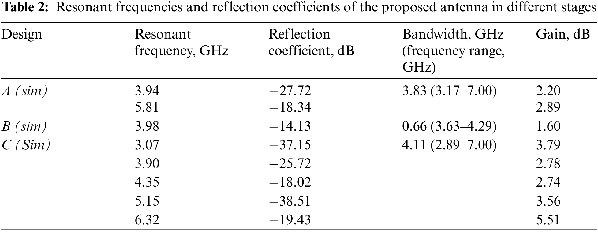
For the second Design B, another layer of felt is added behind the antenna structure with the full ground plane, which then resulted in the decrease of the bandwidth to 0.66 GHz with an FBW of 56.53%. However, the resonant frequency remained similar to the previous Design A at 3.98 GHz.
The final Design C consists of an additional circular parasitic element and a felt substrate layer. This antenna featured an improved bandwidth of up to 4.11 GHz and a relative FBW increase of 23.27% in comparison to Design B. Its reflection coefficient behavior indicates that this antenna is the combination of several wideband resonant frequencies at 3.07 GHz, 3.90 GHz, 4.35 GHz, 5.15 GHz, and 6.32 GHz. This is achieved due to the additional parasitic patches on the layer sandwiched between the two substrates. A narrowband operation is also observed from 1.15 to 1.19 GHz with 40 MHz of bandwidth, with a resonance of 1.17 GHz.
Fig. 4a compares the radiation patterns of Design A, Design B, and Design C at 3.9 GHz. At the ϕ = 0° cut, Design A and Design B featured an omnidirectional radiation pattern. From the graph, the FBR of Design A and Design B is 4.19 dB and 3.01 dB, respectively. The circular parasitic element introduced into the design resulted in a main directional lobe at 0° with a magnitude of 2.62 and –7.81 dB at 149.0°. This then improved the FBR to 10.43 dB. Similarly, at the θ = 90° cut, Design C indicated a reduced back lobe relative to Design A and Design B. The FBR for Design A, Design B and Design C are 4.82, 2.94 and 11.36 dB, respectively. Fig. 4b shows the antenna gain over frequency.
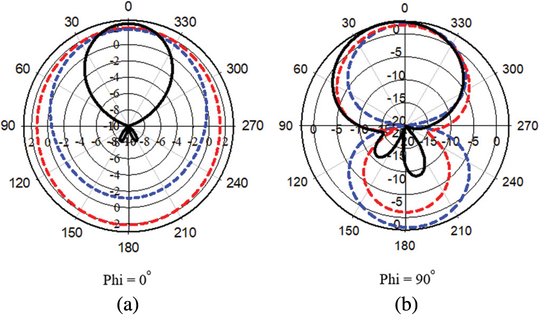

Figure 4: Simulated results from different antenna design stages. (a) Radiation patterns at 3.9 GHz, and (b) Gain variation over frequency
The effects of the dimensional variation of the different designs, four parameters from Design A and Design C, are chosen to be investigated using parametric study. Their values are varied while observing the reflection coefficients and radiation patterns. The results will be presented in the following sections. The major goal of the parametric analysis of proposed antennas is to determine how more sensitive parameters can be more easily used to optimize the performance of the antenna in terms of reflection coefficient, bandwidth, and antenna directivity. This procedure will also provide more degrees of freedom for tuning purposes during the simulation and parametric analysis.
4.1 CPW Ground Length (Design A)
Fig. 5 presents the parametric study for the length of the CPW ground plane, Lcpw1, in Design A. The increase of the CPW length from 6.49 to 10.49 mm widened the bandwidth of the antenna from 3.12 to 3.90 GHz. The changes in this dimension, however, did not affect the shape of the radiation pattern.

Figure 5: Reflection coefficients for the different ground lengths (Lcpw1) for Design A
4.2 Width of Line Connecting the Parasitic Patches (Design A)
The next parametric study is conducted when varying the width of the line connecting the circular and rectangular patch on substrate layer 2. As shown in Fig. 6a, the change of the width has a negligible effect on the antenna reflection coefficient within the 3.4 GHz to 4.5 GHz range. Note that Wfc = 0 mm there is no connecting line between the circular and rectangular patches. On the other hand, the radiation pattern in Fig. 6b indicates that the addition of this line improved antenna directivity with a single back lobe. However, the additional feedline creates another additional back lobe with a higher magnitude.

Figure 6: Parametric study for different line widths between the circular and rectangular parasitic patches Wfc for Design C, (a) Reflection coefficients, (b) Radiation patterns (at ϕ = 0° cut) at 3.9 GHz
4.3 Circular Parasitic Element Radius (Design C)
The next parametric study investigates the effects of the change in radius of the circular parasitic element (Wc) on the performance of Design C. Five values are considered: 0, 6.5, 13.0, 19.5, and 26.0 mm. Fig. 7a showed slight variations of bandwidth due to these changes in Wc: 2.38 GHz, 2.40 GHz, 0.96 GHz, 3.242 GHz, and 2.386 GHz, respectively. On the other hand, the radiation patterns from Design C for the four Wc (of 6.5, 13.0, 19.5, 26.0 mm) illustrated Fig. 7b indicates that the impact on this antenna parameter on the radiation pattern is negligible. However, when Wc = 0 mm (indicating that the circular parasitic element is non-existent), the forward gain reduced significantly.

Figure 7: Parametric study for different radius of the circular parasitic element, (a) Reflection coefficients (b) Radiation patterns (at ϕ = 0° cut) at 3.9 GHz
4.4 Patch Antenna Length (Design C)
The last parametric study is focused on different patch lengths, Lp in Design C. Five values of Lp are considered: 25.2, 28.3, 31.5, 34.5, and 37.8 mm, as shown in Figs. 8a and 8b. Changes in the patch length affected the resonant frequencies of the antenna. For example, the maximum reflection coefficient when Lp = 25.2 mm is –34.70 dB at 2.97 GHz, in comparison to –27.80 dB at 2.66 GHz for Lp = 28.3 mm. Fig. 8b illustrates the radiation patterns resulting from the different Lp of Design C. The increase of the length affected the main lobe's forward directivity significantly, besides the FBR of the antenna.

Figure 8: Parametric study with different lengths of patch antenna in Design C, (a) Reflection coefficients, (b) Radiation patterns (at ϕ = 0° cut) at 3.9 GHz
In this work, antenna Design C is chosen to be fabricated and experimentally evaluated. The fabricated prototype is shown in Fig. 9. The yellow section is the felt substrate, whereas the ShieldIt conductor sections are grey. Reflection coefficient measurements are performed using a vector network analyzer (Agilent Technologies, E5071C) between 1 and 7 GHz. In contrast, a far-field anechoic chamber (Atenlab OTA 500) is used to measure the radiation pattern and gain.

Figure 9: Fabricated antenna prototype (a) Front view (b) Back view
Comparison between simulated and measured reflection coefficients is presented in Fig. 10a. Measurement results indicated that the antenna operated with a 10 dB impedance bandwidth from 3.06 to 7 GHz, with three main resonances: 3.29 GHz, 5.51 GHz and 6.67 GHz. Their S11 are −24.678, −17.654 and −19.621 dB, respectively. Fig. 10b illustrates the simulated and measured gain of the proposed antenna, with a maximum measured gain of 3.79 and 3.55 dB at 3.07 GHz and 5.15 GHz, respectively.

Figure 10: Simulated and measured result for the proposed antenna design C (a) Reflection coefficient, (b) Gain
The simulated and measured results slightly differ due to inaccuracies when fabricating using manual cutting tools, besides the inhomogeneous dielectric constant of the substrate [41]. The differences between simulations and measurements are also affected by the SMA connector losses in practice, as an ideal connector is modeled in simulations. Besides that, the amount of power fed into the antenna in measurements is also affected by the way the epoxy is applied to galvanically connect the SMA connector and fabric [42].
Figs. 11a and 11b depict the radiation patterns of the proposed antenna (Design C) at ϕ = 0° and 90° cuts at 3.07 GHz and 5.15 GHz, respectively. For the ϕ = 0° cut at 3.07 GHz, the main lobe is directed towards the 0° direction with a small back lobe, and the same main direction is observed for the ϕ = 90° cut, with two small back lobes directed at 210° and 130°. The patterns at 5.15 GHz are similarly shaped with the respective 0° and 90° cuts, with a maximum at the 0° direction.
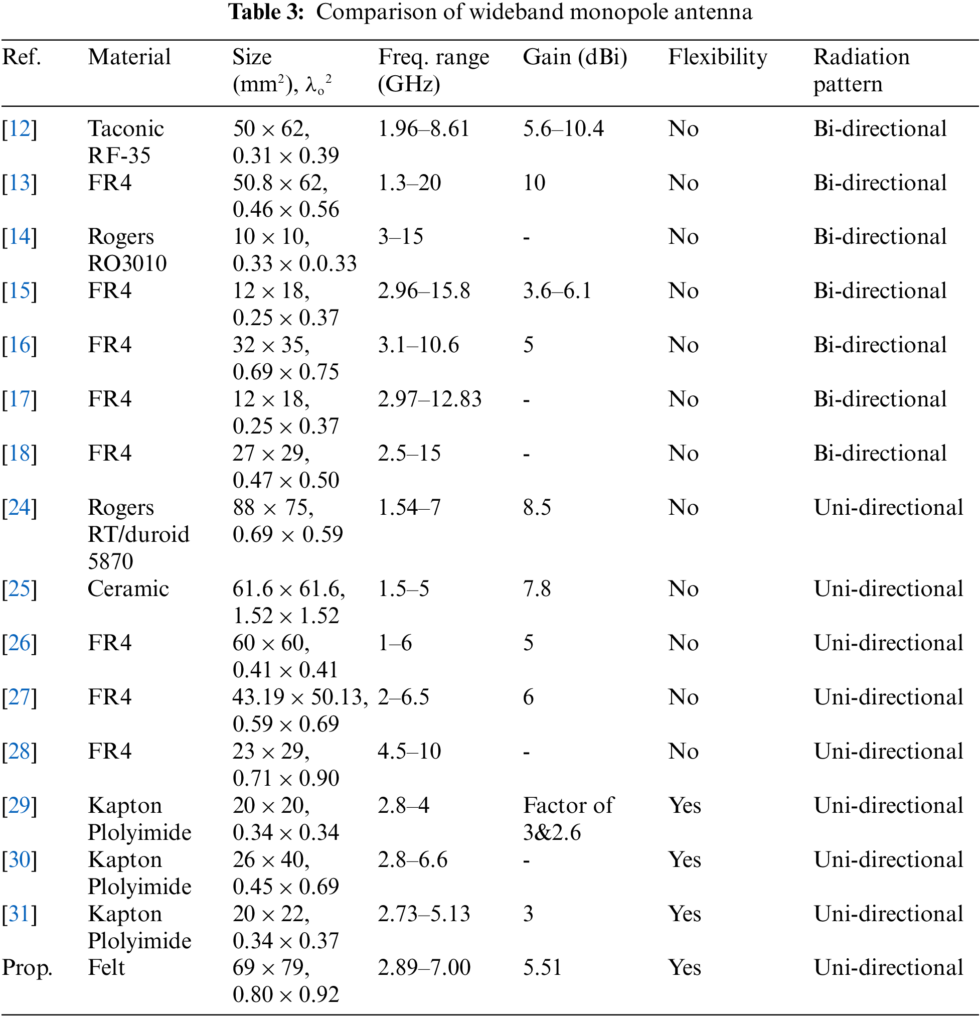
Tab. 3 compares the performance of the proposed antenna with available literature. It is observed to feature flexibility, compact size, wide bandwidth, and unidirectional radiation patterns. This enables it to be potentially applied for MWI due to its conformance to the targeted area when required. Furthermore, the antenna is designed in a wearable format for use on the human body to directly support breast imaging applications.

Figure 11: Radiation pattern of Design C at ϕ = 00 and ϕ = 900 at two resonant frequencies of: (a) 3.07 GHz and (b) 5.15 GHz
In this work, a directional wideband wearable antenna designed using flexible materials is presented. The antenna is designed based on the monopole antenna concept, with an improved directivity and a stable directional radiation pattern. A circular parasitic element and ground plane integrated below the antenna radiator significantly reduced the back radiation level relative to those seen in Design A and Design B. A relatively good agreement between the simulated and measured results is achieved. A directional monopole antenna with an improved directivity and a stable directional radiation pattern was presented by introducing a ground plane with a circular parasitic element at the other layer. This is one of the key to design a good imaging application antenna. The antenna more operates from 2.89 to 7 GHz (in simulations) and from 3.01 to 7 GHz (in measurements) with at least –10 dB of the reflection coefficient. A unidirectional radiation is also observed with a gain of 5.51 dBi, and an FBR of 11.36 dB. Such antenna characteristics with the ultrawideband operation, compact size, and flexible format are suitable as antennas in a microwave imaging application.
Funding Statement: This work was supported in part by the Malaysia Public Service Department (JPA) and Universiti Teknikal Malaysia Melaka (UTeM) under Jurnal/2020/FKEKK/Q00053. P. J. Soh acknowledges the support from the Academy of Finland 6Genesis Flagship (Grant No. 318927).
Conflicts of Interest: The authors declare that they have no conflicts of interest to report regarding the present study.
1. Z. Guan, H. Yu, K. Cuk, Y. Zhang and H. Brenner, “Whole-blood DNA methylation markers in early detection of breast cancer: A systematic literature review,” Cancer Epidemiology Biomarkers & Prevention, vol. 28, no. 3, pp. 496–505, 2018. [Google Scholar]
2. R. Chandra, H. Zhou, I. Balasingham and R. M. Narayanan, “On the opportunities and challenges in microwave medical sensing and imaging,” IEEE Transactions on Biomedical Engineering, vol. 62, no. 7, pp. 1667–1682, 2015. [Google Scholar]
3. M. D. Hossain and A. S. Mohan, “Cancer detection in highly dense breasts using coherently focused time-reversal microwave imaging,” IEEE Transactions on Computational Imaging, vol. 3, no. 4, pp. 928–939, 2017. [Google Scholar]
4. M. Rokunuzzaman, M. Samsuzzaman and M. T. Islam, “Unidirectional wideband 3-D antenna for human head-imaging application,” IEEE Antennas and Wireless Propagation Letters, vol. 16, no. 5, pp. 169–172, 2017. [Google Scholar]
5. S. Kwon and S. Lee, “In-place calibration with single measurement in time-domain microwave breast imaging,” IEEE Antennas and Wireless Propagation Letters, vol. 16, pp. 206–209, 2017. [Google Scholar]
6. M. R. Casu, M. Vacc, J. A. Tobon, A. Pulimeno, I. Sarwar et al., “A COTS-based microwave imaging system for breast-cancer detection,” IEEE Transactions on Biomedical Circuits and Systems, vol. 11, no. 4, pp. 804–814, 2017. [Google Scholar]
7. M. S. R. Bashri and T. Arslan, “Low-cost and compact RF switching system for wearable microwave head imaging with performance verification on artificial head phantom,” IET Microwaves, Antennas & Propagation, vol. 12, no. 5, pp. 706–711, 2018. [Google Scholar]
8. M. T. Islam, M. Z. Mahmud, N. Misran, J. I. Takada and M. Cho, “Microwave breast phantom measurement system with compact side slotted directional antenna,” IEEE Access, vol. 5, pp. 5321–5330, 2017. [Google Scholar]
9. F. Wang and T. Arslan, “A thin-film-based wearable antenna array for breast microwave imaging and diagnosis,” in Proc. Int. Conf. on Microwave Bio, Gothenburg, Sweden, pp. 1–4, 2017. [Google Scholar]
10. M. Rokunuzzaman, M. Samsuzzaman and M. T. Islam, “Unidirectional wideband 3-D antenna for human head-imaging application,” IEEE Antennas and Wireless Propagation Letters, vol. 16, pp. 169–172, 2017. [Google Scholar]
11. S. Alani, Z. Zakaria and A. Ahmad, “Miniaturized UWB elliptical patch antenna for skin cancer diagnosis imaging,” International Journal Electrical & Computers Engineering, vol. 10, no. 2, pp. 1422–1429, 2020. [Google Scholar]
12. M. Abbak, M. N. Akıncı, M. Çayören and I. Akduman, “Experimental microwave imaging with a novel corrugated Vivaldi antenna,” IEEE Transactions Antennas & Propagation, vol. 65, no. 6, pp. 3302–3307, 2017. [Google Scholar]
13. B. Biswas, R. Ghatak and D. R. Poddar, “A fern fractal leaf inspired wideband antipodal Vivaldi antenna for microwave imaging system,” IEEE Transaction. Antennas & Propagation, vol. 65, no. 11, pp. 6126–6129, 2017. [Google Scholar]
14. M. Ahadi, W. Z. W. Hasan, M. I. B. Saripan and M. B. M. Isa, “Square monopole antenna for microwave imaging, design and characterisation,” IET Microwave, Antennas & Propagation, vol. 9, no. 1, pp. 49–57, 2015. [Google Scholar]
15. N. Ojaroudi and N. Ghadimi, “Omnidirectional microstrip monopole antenna design for use in microwave imaging systems,” Microwave& Optical Technology Letters, vol. 57, no. 2, pp. 395–401, 2015. [Google Scholar]
16. M. H. Bah, J. Hong and D. A. Jamro, “Ground slotted monopole antenna design for microwave breast cancer detection based on time reversal music,” Progress in Electromagnetic Research C, vol. 59, no. 4, pp. 117–126, 2015. [Google Scholar]
17. N. Ojaroudi, M. Ojaroudi and N. Ghadimi, “UWB omnidirectional square monopole antenna for use in circular cylindrical microwave imaging systems,” IEEE Antennas Wireless Propagation Letters, vol. 11, pp. 1350–1353, 2012. [Google Scholar]
18. S. Subramanian, B. Sundarambal and D. Nirmal, “Investigation on simulation-based specific absorption rate in ultra-wideband antenna for breast cancer detection,” IEEE Sensors Journal, vol. 18, no. 24, pp. 10002–10009, 2018. [Google Scholar]
19. R. A. A. Kamaruddin, I. B. M. Ibrahim, A. J. A. Al-Gburi, Z. Zakaria, N. A. Shairi et al., “Return loss improvement of radial line slot array antennas on closed ring resonator structure at 28 GHz,” Przegląd Elektrotechniczny, vol. 1, no. 5, pp. 65–69, 2021. [Google Scholar]
20. N. A. Jan, S. H. Kiani, D. A. Sehrai, M. R. Anjum, A. Iqbal et al., “Design of a compact monopole antenna for UWB applications,” Computers, Materials & Continua, vol. 69, no. 1, pp. 679–694, 2021. [Google Scholar]
21. N. A. Jan, S. H. Kiani, F. Muhammad, D. A. Sehrai, A. Iqbal et al., “V-Shaped monopole antenna with Chichena Itzia inspired defected ground structure for UWB applications,” Computers, Materials & Continua, vol. 65, no. 1, pp. 19–32, 2020. [Google Scholar]
22. A. J. A. Al-Gburi, I. B. M. Ibrahim, Z. Zakaria, B. H. Ahmad, N. A. Bin Shairi et al., “High gain of UWB planar antenna utilising FSS reflector for UWB applications,” Computers, Materials & Continua, vol. 70, no. 1, pp. 1419–1436, 2022. [Google Scholar]
23. A. J. A. Al-Gburi, I. M. Ibrahim and Z. Zakaria, “An ultra-miniaturized MCPM antenna for ultra-wideband applications,” Journal of Nano- and Electronic Physics, vol. 13, no. 5, pp. 05012-1–05012-4, 2021. [Google Scholar]
24. A. J. A. Al-Gburi, I. M. Ibrahim, Z. Zakaria, M. Y. Zeain, H. Alwareth et al., “High gain of UWB CPWfed mercedes shaped printed monopole antennas for UWB applications,” Przegląd Elektrotechniczny, vol. 2021, no. 5, pp. 70–73, 2021. [Google Scholar]
25. A. J. A. Al-gburi, I. M. Ibrahim, K. S. Ahmad, Z. Zakaria, M. Y. Zeain et al., “A miniaturised UWB FSS with stop-band characteristics for EM shielding applications,” Przegląd Elektrotechniczny, vol. 2021, no. 8, pp. 142–145, 2021. [Google Scholar]
26. Y. L. Nga, Z. Zahriladha, N. A. Shairi, H. Alsariera and R. Alahnomi, “Design and investigation on wideband antenna based on Polydimethylsiloxane (PDMS) for medical imaging application,” Przegląd Elektrotechniczny, vol. 1, pp. 91–94, 2020. [Google Scholar]
27. F. Ahmed, N. Hasan and M. H. M. Chowdhury, “A compact low-profile ultra-wideband antenna for biomedical applications,” in Proc. Int. Conf. on Electrical, Computer and Communication Engineering, Cox's Bazar, Bangladesh, pp. 87–90, 2017. [Google Scholar]
28. M. T. Islam, M. Z. Mahmud, N. Misran, J. Takada and M. Cho, “Microwave breast phantom measurement system with compact side slotted directional antenna,” IEEE Access, vol. 5, pp. 5321–5330, 2017. [Google Scholar]
29. S. Latif, D. F. Tapia, D. R. Herrera, M. S. Nepote, M. S. Pistorius et al., “A directional antenna in a matching liquid for microwave radar imaging,” International Journal of Antennas and Propagation, vol. 2015, pp. 1–8, 2015. [Google Scholar]
30. S. Latif, D. F. Tapia, S. Pistorious and L. Shafai, “A planar ultrawideband elliptical monopole antenna with reflector for breast microwave imaging,” Microwave and Optical Technology Letters, vol. 56, no. 4, pp. 808–813, 2014. [Google Scholar]
31. A. Edalati, W. Shao, T. McCollough and W. McCollough, “A novel cavity backed monopole antenna with UWB unidirectional radiation,” Progress in Electromagnetics Research C, vol. 72, pp. 1–13, 2017. [Google Scholar]
32. M. Klemm, I. J. Craddock, J. A. Leendertz, A. Preece and R. Benjamin, “Radar-based breast cancer detection using a hemispherical antenna array experimental results,” IEEE Transactions on Antennas and Propagation, vol. 57, no. 6, pp. 1692–1704, 2009. [Google Scholar]
33. H. Bahrani, E. Porter, A. Santorelli, B. Gosselin, M. Popovic et al., “Flexible 16 antenna array for microwave breast cancer detection,” IEEE Transactions on Biomedical Engineering, vol. 62, no. 10, pp. 2516–2525, 2015. [Google Scholar]
34. A. J. A. Al-gburi, I. B. M. Ibrahim, Z. Zakaria and N. Farzana, “Wideband microstrip patch antenna for sub 6 GHz and 5G applications,” Przegląd Elektrotechniczny, vol. 2021, no. 11, pp. 26–29, 2021. [Google Scholar]
35. A. Afyf, L. Bellarbi, A. Achour, N. Yaakoubi, A. Errachid et al., “UWB thin film flexible antenna for microwave thermography for breast cancer detection,” in Proc. Int. Conf. on Electrical and Information Technologies, Tangiers, Morocco, pp. 425–429, 2016. [Google Scholar]
36. A. Baskakova, “Improved time efficiency for simulation of an antenna for near-field distance measurements in CST studio suite,” in Proc. Int. Conf. on Antennas Design and Measurement Int. Conf., Petersburg, Russia, pp. 26–29, 2019. [Google Scholar]
37. L. Zhang, S. Gao, Q. Luo, P. R. Young, Q. Li et al., “Single-feed ultra-wideband circularly polarized antenna with enhanced Front-to-Back ratio,” IEEE Transactions on Antennas and Propagation, vol. 64, no. 1, pp. 355–360, 2016. [Google Scholar]
38. A. J. A. Al-Gburi, I. Ibrahim, Z. Zakaria and A. D. Khaleel, “Bandwidth and gain enhancement of ultra-wideband monopole antenna using MEBG structure,” ARPN Journal of Engineering and Applied Sciences, vol. 14, no. 10, pp. 3390–3393, 2019. [Google Scholar]
39. A. J. A. Al-Gburi, I. Ibrahim, Z. Zakaria, M. K. Abdulhameed and T. Saeidi, “Enhancing gain for UWB antennas using FSS: A systematic review,” Mathematics, vol. 9, no. 24, pp. 3301, 2021. [Google Scholar]
40. Y. Li, W. Li and Q. Ye, “A CPW-fed circular wide-slot UWB antenna with dual-notch bands by combining slot and parasitic element techniques,” Microwave and Optical Technology Letters, vol. 56, no. 5, pp. 1240–1244, 2014. [Google Scholar]
41. A. Mehdi, K. Abdennacer and S. Mounir, “Analysis of the discrepancies fabricating error of microstrip antenna,” International Journal of Research and Reviews in Applied Sciences, vol. 9, no. 3, pp. 405–412, 2011. [Google Scholar]
42. K. Y. Yazdandoost and K. Sato, “Fabrication error in resonant frequency of microstrip antenna,” in Proc. Int. Conf. on Micromechatronics and Human Science, Nagoya, Japan, pp. 41–44, 2001. [Google Scholar]
 | This work is licensed under a Creative Commons Attribution 4.0 International License, which permits unrestricted use, distribution, and reproduction in any medium, provided the original work is properly cited. |