DOI:10.32604/cmc.2022.024824
| Computers, Materials & Continua DOI:10.32604/cmc.2022.024824 | |
| Article |
HARQ Optimization for PDCP Duplication-Based 5G URLLC Dual Connectivity
1Samsung Research, Seoul, 06765, Korea
2Samsung Electronics, Suwon, 16677, Korea
3School of Electrical and Electronic Engineering, Yonsei University, Seoul, 03722, Korea
*Corresponding Author: Jong-Moon Chung. Email: jmc@yonsei.ac.kr
Received: 01 November 2021; Accepted: 07 December 2021
Abstract: Packet duplication (PD) with dual connectivity (DC) was newly introduced in the 5G New Radio (NR) specifications to meet the stringent ultra reliable low latency communication (URLLC) requirements. PD technology uses duplicated packets in the packet data convergence protocol (PDCP) layer that are transmitted via two different access nodes (ANs) to the user equipment (UE) in order to enhance the reliability performance. However, PD can result in unnecessary retransmissions in the lower layers since the hybrid automatic retransmission request (HARQ) operation is unaware of the transmission success achieved through the alternate DC link to the UE. To overcome this issue, in this paper, a novel duplication-aware retransmission optimization (DRO) scheme is proposed to reduce the resource usage induced by unnecessary HARQ retransmissions. The proposed DRO scheme can minimize the average channel use while satisfying the URLLC requirements. The proposed DRO scheme derives the optimal HARQ retransmission attempts for different ANs by solving a nonlinear integer programming (NLIP) problem. The performance of the proposed DRO scheme was evaluated using MATLAB simulation and is compared to the existing 5G HARQ support schemes. The simulations results show that the proposed DRO scheme can provide a 14.71% and 15.11% reduced average channel use gain compared to the selective data duplication upon failure (SDUF) scheme and latency-aware dynamic multi-connectivity algorithm (LADMA) scheme, respectively, which are the existing 5G PD schemes that use HARQ.
Keywords: 5G networks; URLLC; dual connectivity; retransmission; packet duplication
Ultra reliable low latency communication (URLLC) is one of the fifth generation (5G) mobile service modes that can support high reliability wireless networking with very low time delays. Although different design goals are required for different URLLC applications (e.g., autonomous driving, drone control, factory automation, remote surgery), one of the stringent quality of service (QoS) requirements for URLLC traffic is the 99.999% reliability within 1 ms packet latency [1]. To support URLLC traffic in 5G networks, novel design concepts have been proposed in the physical (PHY) and medium access control (MAC) layers. For example, a short transmission time interval (sTTI) and faster processing speeds were applied to achieve the low latency requirements, and hybrid automatic repeat request (HARQ) was enhanced to achieve the high reliability requirements. However, in addition to the novel PHY and MAC designs, changes in the upper layers are also required to meet the stringent URLLC service requirements.
Dual connectivity (DC) was first introduced in the 3GPP Release 12 specifications in order to enable user equipment (UE) to access two different access nodes (ANs) simultaneously. The initial objective of DC was to achieve downlink (DL) data rate enhancement by splitting the user plane (UP) data, however, DC was recently extended to support reliability enhancements by exploiting packet duplication (PD). In the 3GPP Release 15 specifications, the PD functionality was adopted as a part of the packet data convergence protocol (PDCP) layer defined under the name PDCP duplication [2]. By duplicating URLLC packets in the PDCP layer and transmitting them through different ANs, an UE can obtain macro diversity. As a result, PD enables an UE to obtain not only higher transmission reliability, but reduced latency since it can alleviate the potential need for a retransmission.
However, PDCP duplication can give rise to unnecessary retransmissions if HARQ is operated in the lower layers. When duplicated packets are transmitted via different ANs, the packet delivered through one AN might be successful and the other packet sent through the other AN may be unsuccessful. In this case, the HARQ process will not be needed, but HARQ will be executed since the HARQ entity would be unaware of the successful packet delivery through the other AN. This redundant retransmission of HARQ will lead to a waste of radio resources. As the number of data traffic and connected devices in the mobile network increase, efficient management of radio resources become more essential in 5G networks [3,4]. In order to overcome this problem, a novel HARQ optimization scheme that cooperates with the PDCP duplication process is proposed. The original contributions of this paper are summarized as follows.
• To minimize redundant wireless resource usage in PDCP duplication, the duplication-aware retransmission optimization (DRO) scheme is proposed.
• The expected channel use model and the corresponding optimization statement is derived considering the HARQ latency and packet reliability model.
• The optimal number of HARQ retransmission attempts for different ANs is derived by solving a nonlinear integer programming (NLIP) problem based on a gradient descent method.
• The performance of DRO is compared to non-optimal retransmission control schemes such as selective data duplication upon failure (SDUF) and latency-aware dynamic multi-connectivity algorithm (LADMA), and the simulation results show that DRO can provide the lowest average channel use while satisfying the URLLC requirements.
Several papers have focused on the reliability enhancement of PDCP duplication in 5G networks. In [5], the feasibility and effectiveness of PDCP duplication were investigated, where the numerical results show that PD can help satisfy the latency and reliability requirement of URLLC. In [6], a reliability-oriented multi-connectivity (MC) concept was proposed based on PDCP duplication, which includes a novel admission mechanism to control the number of MC users. In [7], an analytical study on the reliability of MC was conducted while considering HARQ retransmission. In [8], the LADMA scheme was proposed to reduce the resource usage while satisfying the latency requirement, which activates MC only for users with a high latency violation probability. In [9], the SDUF scheme was proposed to reduce the radio resource consumption by activating DC only upon a transmission failure on the primary link. However, the number of HARQ retransmissions and flexible numerology which have an effect on the overall latency are not considered in the previous PDCP duplication works.
Other papers have studied on the HARQ retransmission aspect in 5G networks. These works focused on HARQ and efficent resource allocation for single connected users. In [10], an optimal resource allocation and repetition coding based HARQ retransmission scheme was proposed to minimize the necessary bandwidth required for URLLC traffic. In [11], a novel resource allocation scheme for retransmissions was proposed, where corresponding analytical models for loss rates were derived. In [12], a Pollaczek–Khinchine (P-K) formula based quadratic optimization (PFQO) scheme was proposed, which can minimize the URLLC bandwidth requirement based on the queueing analysis of HARQ.
Consider an UE which is connected to the master gNB (M-gNB) and the secondary gNB (S-gNB) simultaneously in the NR-NR DC (NR-DC) architecture [13], as shown in Fig. 1. The index
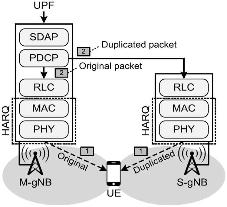
Figure 1: Example of the NR-DC architecture when packet duplication occurs in the PDCP layer
A packet error occurs after a decoder fails to correct an erroneous packet, and thereby a retransmission of the erroneous packet is induced. Let
where

Since URLLC packets are small in general, finite blocklength theory can be used to derive the amount of resource usage [16]. An URLLC packet of L bits can be transmitted with the PER of
where
Since PDCP duplication is used in the NR-DC architecture, the reliability of the URLLC packet can be enhanced. Let
In the NR-DC architecture, the URLLC packet fails if both the original packet and the duplicated packet are lost at the M-gNB and S-gNB. Consequently, the packet reliability in the NR-DC architecture
Let
where
where
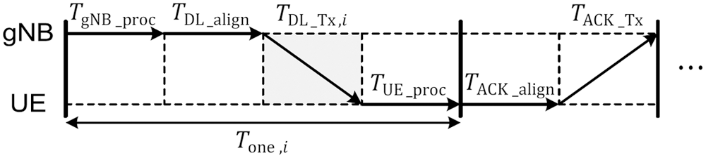
Figure 2: URLLC latency timeline based on HARQ retransmission mechanism
The proposed DRO technique is a selective duplication scheme [8,9], where a duplicated packet of the S-gNB is transmitted only when an initial transmission of the M-gNB fails. Therefore, unnecessary transmissions of the duplicated packets are prevented and the total number of transmission attempts can be effectively reduced. Fig. 3 shows an example of the selective duplication scheme when an initial transmission of the M-gNB fails. An incoming packet is duplicated in the PDCP layer of the M-gNB and the duplicated packet is forwarded to the S-gNB only after HARQ NACK reception. Otherwise, if the initial transmission of the M-gNB is successful, ACK is transmitted instead of NACK and the duplicated packet in the M-gNB is discarded. In addition to selective duplication, DRO derives the optimal number of maximum transmission attempts to minimize the radio resource consumption.
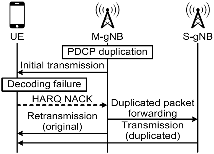
Figure 3: Signaling flow of selective duplication, where duplicated packet forwarding and transmission is carried out only after HARQ NACK reception
Let
where (C1) represents the URLLC reliability condition, in which the reliability
In addition, (C3) represents the channel use condition. The channel use in the time-frequency plane can be derived by the required bandwidth resource
where
Lemma 1. Suppose
Proof. The expected channel use
The expected number of transmission attempts for M-gNB can be derived as
However, the expected number of transmission attempts for the S-gNB can be derived as
since the S-gNB transmits a duplicated packet after transmission failure of the M-gNB. Therefore, the expected channel use
Therefore, the partial differentials of
In addition, the partial differential
The approximation gap of
Since
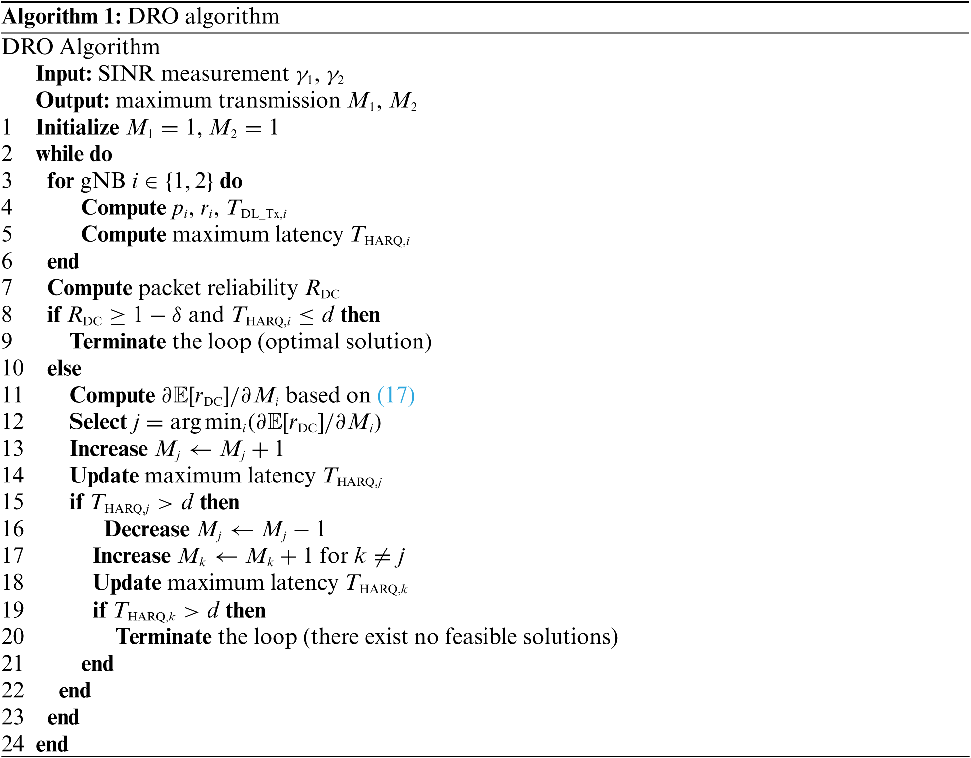
As the input, the SINR measurements with respect to the reference signal are used, which are reported periodically from the UE. First, the maximum number of transmission attempts are initialized to 1 in line 1, then the DRO scheme iterates a loop until it achieves the URLLC requirements in line 2. The maximum latency
In this section, the performance of the DRO scheme is evaluated using MATLAB simulation, where the URLLC packet size was set to
In the simulation, NR gNBs form a hexagonal-shaped cellular coverage. The M-gNB is located at (−50, 0), and the S-gNB is located at (50), where the carrier frequency is set to 3.5 GHz. Since DC is activated in the cell edge regions and cell range extension (CRE) is considered, the UE is initially located at (−10, 15) and moves toward (20, 15). The performance of the DRO scheme was compared with LADMA [8] and SDUF [9] when the maximum transmission attempts
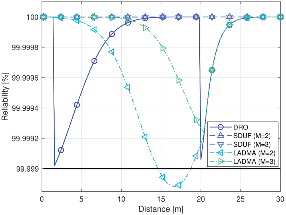
Figure 4: Simulation results with respect to the reliability performance
In Fig. 4, the reliability of the DRO scheme is presented, where the black bold line represents the reliability condition (
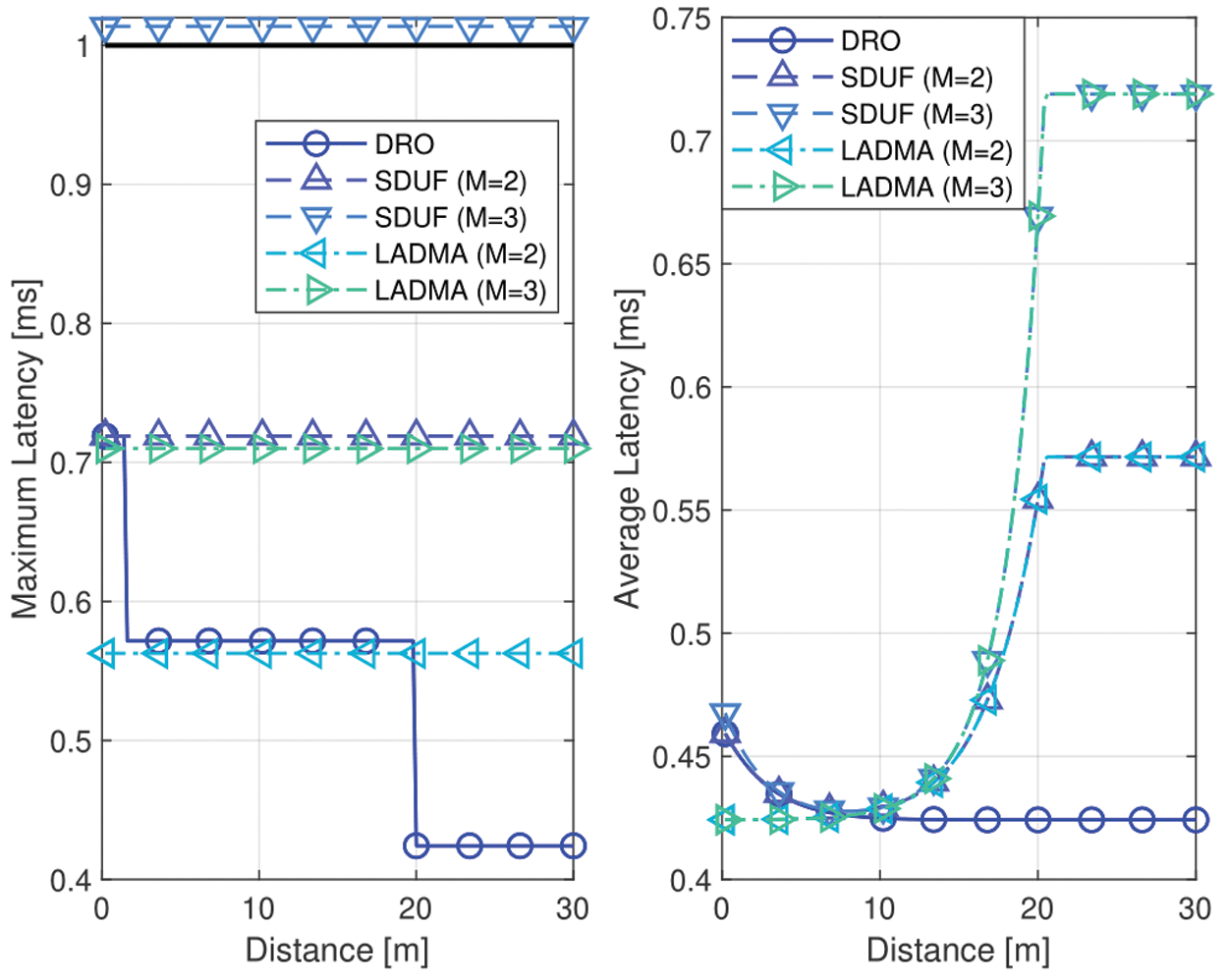
Figure 5: Simulation results with respect to the latency performance
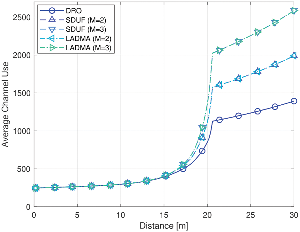
Figure 6: Simulation results with respect to the average channel use performance
In Fig. 5, the maximum latency and average latency of the DRO scheme is presented, where the black bold line in (a) represents the latency condition (
In Fig. 6, the average channel use of the DRO scheme is presented with respect to the distance of the UE movement. Based on the simulation results of Figs. 4 and 5, the proposed DRO scheme can satisfy the URLLC QoS conditions for the entire range of interest. Furthermore, Fig. 6 shows that the DRO scheme can provide the lowest average channel use compared to LADMA and SDUF for the entire range of interest. Under the feasible region of the URLLC QoS conditions, the DRO scheme can provide a 11.64% and 17.78% reduced average channel use when compared to SDUF with
In this paper, a PD aware HARQ retransmission scheme named DRO is proposed, which can minimize the average resource usage while satisfying the URLLC requirements in the NR-DC architecture. The proposed DRO scheme derives the optimal value of the maximum transmission attempts for each gNB based on the average channel use. The simulation results show that the proposed DRO scheme can provide a significant performance gain compared to the existing PD schemes, which include LADMA and SDUF.
Funding Statement: This work was supported by the Institute of Information & communications Technology Planning & Evaluation (IITP) grant funded by the South Korea government (MSIT, 2021-0-00040, Development of intelligent stealth technology for information and communication resources for public affairs and missions).
Conflicts of Interest: The authors declare that they have no conflicts of interest to report regarding the present study.
1. M. Bennis, M. Debbah and H. V. Poor, “Ultrareliable and low-latency wireless communication: Tail, risk, and scale,” Proceedings of the IEEE, vol. 106, no. 10, pp. 1834–1853, Oct2018. [Google Scholar]
2. 3GPP, “NR and NG-RAN overall description (Release 16),” 3GPP TS 38.300 v16.2.0, Jul. 2020. [Google Scholar]
3. F. Xu, P. Zou, H. Wang, H. Cao, X. Fang et al., “Resource allocation for D2D communication in cellular networks based on stochastic geometry and graph-coloring theory,” KSII Transactions on Internet and Information Systems, vol. 14, no. 12, pp. 4946–4960, 2020. [Google Scholar]
4. Z. Li, X. Wang, J. Zhang, W. Huang and Y. Tian, “Temporal and spatial traffic analysis based on human mobility for energy efficient cellular network,” KSII Transactions on Internet and Information Systems, vol. 15, no. 1, pp. 114–130, 2021. [Google Scholar]
5. J. Rao and S. Vrzic, “Packet duplication for URLLC in 5G: Architectural enhancements and performance analysis,” IEEE Network, vol. 32, no. 2, pp. 32–40, 2018. [Google Scholar]
6. N. H. Mahmood, M. Lopez, D. Laselva, K. Pedersen and G. Berardinelli, “Reliability oriented dual connectivity for URLLC services in 5G new Radio,” in 2018 15th Int. Symp. on Wireless Communication Systems (ISWCS), Lisbon, Portugal, pp. 1–6, Aug. 2018. [Google Scholar]
7. N. H. Mahmood, A. Karimi, G. Berardinelli, K. I. Pedersen and D. Laselva, “On the resource utilization of multi-connectivity transmission for URLLC services in 5G new Radio,” in 2019 IEEE Wireless Communications and Networking Conf. Workshops (WCNCW), Marrakech, Morocco, pp. 1–6, Apr. 2019. [Google Scholar]
8. N. H. Mahmood and H. Alves, “Dynamic multi-connectivity activation for ultra-reliable and low-latency communication,” in 2019 16th Int. Symp. on Wireless Communication Systems (ISWCS), Oulu, Finland, pp. 1–5, Aug. 2019. [Google Scholar]
9. M. Centenaro, D. Laselva, J. Steiner, K. Pedersen and P. Mogensen, “System-level study of data duplication enhancements for 5G downlink URLLC,” IEEE Access, vol. 8, pp. 565–578, 2020. [Google Scholar]
10. A. Anand and G. d. Veciana, “Resource allocation and HARQ optimization for URLLC traffic in 5G wireless networks,” IEEE Journal on Selected Areas in Communications, vol. 36, no. 11, pp. 2411–2421, 2018. [Google Scholar]
11. S. E. Elayoubi, P. Brown, M. Deghel and A. Galindo-Serrano, “Radio resource allocation and retransmission schemes for URLLC over 5G networks,” IEEE Journal on Selected Areas in Communications, vol. 37, no. 4, pp. 896–904, 2019. [Google Scholar]
12. H. Jang, J. Kim, W. Yoo and J. -M. Chung, “URLLC mode optimal resource allocation to support HARQ in 5G wireless networks,” IEEE Access, vol. 8, pp. 126797–126804, 2020. [Google Scholar]
13. 3GPP, “Multi-connectivity; Overall description (Release 16),” 3GPP TS 37.340 v16.7.0, Sep. 2021. [Google Scholar]
14. J. Ramis and G. Femenias, “Cross-layer design of adaptive multirate wireless networks using truncated HARQ,” IEEE Transactions on Vehicular Technology, vol. 60, no. 3, pp. 944–954, 2011. [Google Scholar]
15. H. D. Le, C. T. Nguyen, V. V. Mai and A. T. Pham, “On the throughput performance of TCP cubic in millimeter-wave cellular networks,” IEEE Access, vol. 7, pp. 178618–178630, 2019. [Google Scholar]
16. Y. Polyanskiy, H. V. Poor and S. Verdu, “Channel coding rate in the finite blocklength regime,” IEEE Transactions on Information Theory, vol. 56, no. 5, pp. 2307–2359, 2010. [Google Scholar]
17. 3GPP, “Email discussion/approval on converging the proposals for eURLLC processing timeline,” 3GPP R1-1901472, Jan. 2019. [Google Scholar]
 | This work is licensed under a Creative Commons Attribution 4.0 International License, which permits unrestricted use, distribution, and reproduction in any medium, provided the original work is properly cited. |