DOI:10.32604/cmc.2022.020259
| Computers, Materials & Continua DOI:10.32604/cmc.2022.020259 | |
| Article |
Deep Learning Control for Autonomous Robot
1College of Engineering, Muzahimiyah Branch, King Saud University, Riyadh, 11451, Saudi Arabia
2Laboratory for Analysis, Conception and Control of Systems, LR-11-ES20, Department of Electrical Engineering National Engineering School of Tunis, Tunis El Manar University, 1002, Tunisia
3King Abdulaziz City for Science and Technology, Saudi Arabia
4College of Computing and Information Technology, University of Bisha, Bisha, 67714, Saudi Arabia
*Corresponding Author: Saad Alhuwaimel. Email: huwaimel@ksacst.edu.sa
Received: 17 May 2021; Accepted: 13 December 2021
Abstract: Several applications of machine learning and artificial intelligence, have acquired importance and come to the fore as a result of recent advances and improvements in these approaches. Autonomous cars are one such application. This is expected to have a significant and revolutionary influence on society. Integration with smart cities, new infrastructure and urban planning with sophisticated cyber-security are some of the current ramifications of self-driving automobiles. The autonomous automobile, often known as self-driving systems or driverless vehicles, is a vehicle that can perceive its surroundings and navigate predetermined routes without human involvement. Cars are on the verge of evolving into autonomous robots, thanks to significant breakthroughs in artificial intelligence and related technologies, and this will have a wide range of socio-economic implications. However, in order for these automobiles to become a reality, they must be endowed with the perception and cognition necessary to deal with high-pressure real-life events and make proper judgments and take appropriate action. The majority of self-driving car technologies are based on computer systems that automate vehicle control parts. From forward-collision warning and antilock brakes to lane-keeping and adaptive drive control, to fully automated driving, these technological components have a wide range of capabilities. A self-driving car combines a wide range of sensors, actuators, and cameras. Recent researches on computer vision and deep learning are used to control autonomous driving systems. For self-driving automobiles, lane-keeping is crucial. This study presents a deep learning approach to obtain the proper steering angle to maintain the robot in the lane. We propose an advanced control for a self-driving robot by using two controllers simultaneously. Convolutional neural networks (CNNs) are employed, to predict the car’ and a proportional-integral-derivative (PID) controller is designed for speed and steering control. This study uses a Raspberry PI based camera to control the robot car.
Keywords: Autonomous car; cascade PID control; deep learning; convolutional neural network; differential drive system; raspberry PI; road lane detector
Since the middle of the 1980s, many universities, research centers, car companies, and companies in other industries have studied and developed self-driving cars (Fig. 1) (also known as autonomous cars and driverless cars).
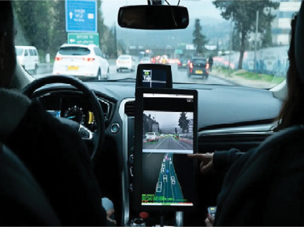
Figure 1: self-driving car
The Navlab mobile platform [1], the University of Pavia and University of Parma's car, ARGO [2], and UBM's vehicles, VaMoRs and VaMP, are all important examples of self-driving car research platforms from the last two decades. DARPA (Defense Advanced Research Projects Agency) conducted a test in 2004 to see if self-driving cars could complete the course, but no one did. Sebastian Thrun led his team to victory in the second challenge, which took place in 2005. Google developed the efficient self-driving car technology in the Toyota Prius, which was also licensed by the Department of Motor Vehicles in 2012 [3].
Deep learning and artificial intelligence have been key technologies behind many breakthroughs in computer vision and robotics over the last decade [4,5]. They also have a huge influence on the emerging autonomous driving revolution in academia and industry. A self-driving or autonomous car can sense its environment and travel to a pre-determined destination without the assistance of a human driver on a route that has not been specifically built for it [6].
With the advent of technologies and transportation, more cars now have self-driving modes to help passengers in protecting their health when driving long distances and reducing the risk of traffic accidents. The advantages of self-driving vehicles include the ability to predict and manage traffic problems and provide built-up accessibility for all users. Academic and industry research groups have developed various low-cost systems for studying research problems in autonomous driving and control [7–12].
Self-driving vehicles must maintain their lane. Because of numerous sensors on autonomous vehicles, such as radar, LiDAR, ultrasonic sensors, and infrared cameras, ordinary color cameras remain critical because of their low cost and capacity to collect rich data [13,14]. Lane detection is a critical environmental perception tool for creating a self-driving vehicle. It is critical to monitor a vehicle's movement in compliance with the road lane in which it is driving [10,11,15,16].
After detecting two lines, we must quantify and draw a virtual line in the center, then approximate the offset angle between the vehicle's body and the virtual line to change the vehicle's steering such that the vehicle is still in the middle of two lines under all circumstances [17].
The above-mentioned steering angle calculations are complicated and can result in several errors. Several roads have no lane or blurry lane markings. Furthermore, as cars are speeding along a sloping driveway, the camera installed previously will point to the sky and fail to keep up with the lane ahead, which can also lead to erroneous detection [18].
Recent developments in low-cost sensors and small-scale robot cars have provided new incentives and prospects for solving and overcoming the limitations, such as TurtleBot [19], Donkey car [20], and DFROBOT [21]. Students and researchers interested in self-driving can use these robot cars. They are also permitted to design and build their robot cars using low-cost sensors and units, such as remote-control cars, Raspberry Pi (RPi), GPS, Wi-Fi, Bluetooth, and single/stereo cameras [22].
Convolutional neural networks (CNNs) have been the most prevalent deep learning architecture due to its efficacy on image classification problems since their introduction in the 1990. For self-driving vehicles, deep learning has been widely used. Obstacle detection, scene recognition, and lane recognition are all major issues in self-driving cars that must be solved [23].
However, using CNNs, [24] showed an end-to-end learning method for self-driving vehicles. Reference [25] introduced using YOLO and CNN algorithms, which allow the system to detect road lanes, objects, and make suggestions to the driver. However, the system was recommended only for use on highways, not on city streets.
This study proposes a self-driving vehicle prototype, in which experimental hardware components and methodologies are used in a self-driving car. The device consists of an RPi as the key part operating the algorithms, cameras linked to the RPi, and various sensors. The Arduino is also a critical component because it controls the vehicle motors and their movements.
2 Autonomous Robot Car Architecture
Training the car in a real-time environment, such as a motorway or road with heavy traffic, is a risky and cost-driven task. To manage such a situation, a small RPi-based car and a custom environment were established so that training can be conducted feasibly.
This section describes the architecture and system block. A suitable configuration was chosen for developing a line-tacking robot using a Pi camera connected to the motor driver IC through an Raspberry PI3 B+. Fig. 2 illustrates this configuration.
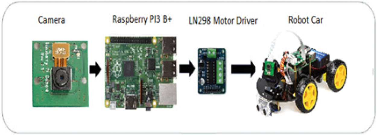
Figure 2: self-driving robot structure
The system's implementation on the Raspberry Pi ensured the following functions:
• Data and image collection using the Pi camera
• PID controllers and the expected steering angle are used to determine the speed of the left and right motors
• directing the robot in the desired direction.
3 Deep Learning Based PID Control for Self-Driving Vehicle
To make the vehicle autonomous, image processing, AI, and deep learning approaches are used. To control the robot, a cascaded PID controller is designed. Fig. 3 shows the overall proposed control diagram.
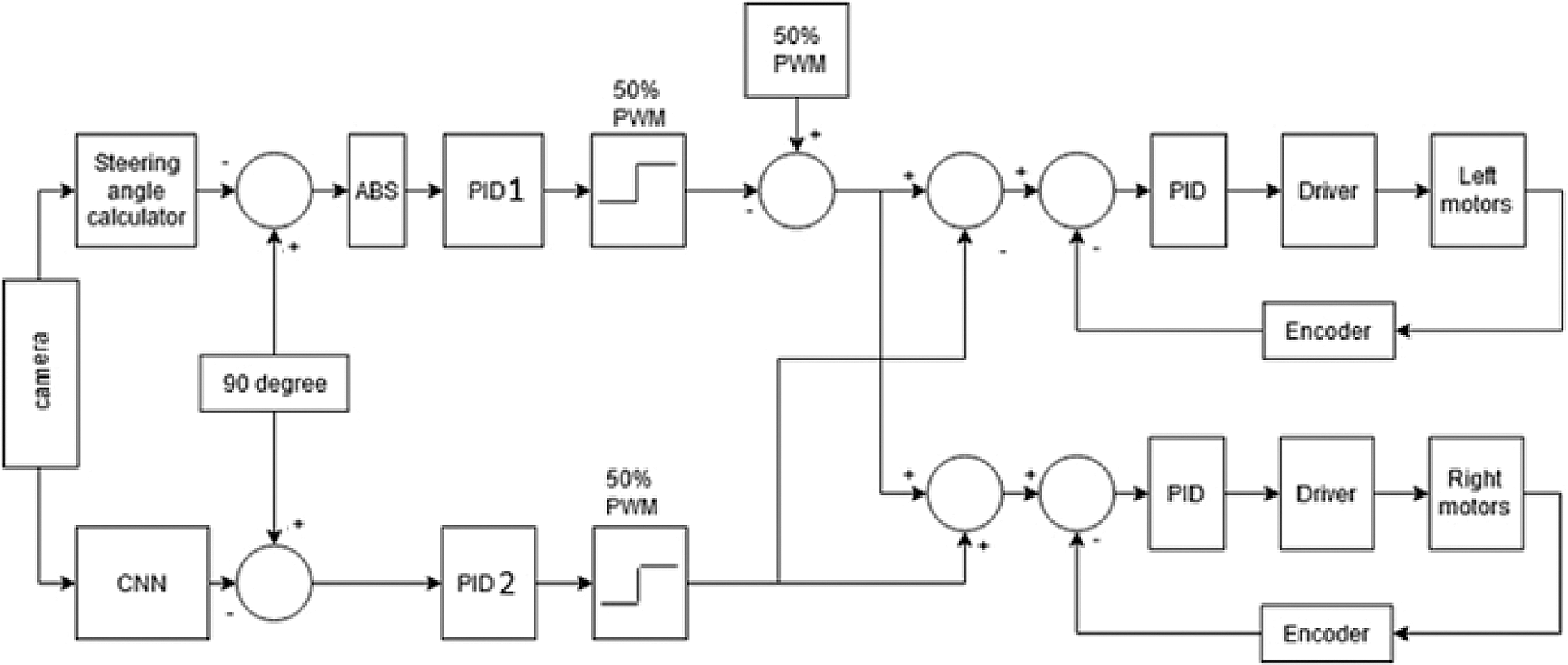
Figure 3: Main controller for autonomous lane-keeping robot
To control the robot's maneuver, steering control is needed. Therefore, two PID controllers are employed to control the robot's direction. The first PID controls the throttling speed (basic speed) based on the steering angle calculation. The steering angle is determined using an image processing controller. The input of the system is images; the output is steering angle in degrees (θ). Algorithm is applied on one single image (one frame) and will be repeated on all frames. The second PID determines the car's deviation speed using a CNN θ prediction. The trained network receives an image frame from a single forward-looking camera as input and generates a predicted θ value as the output at each control period.
If θ = 90°, the car will drive forward without needing to be steered. A constant throttling speed of 50% PWM is used to ensure that the robot car moves forward at 50% off the total speed. If θ > 90°, the car should steer to the right; otherwise, it should steer left.
The driving signals for the left and right motors are calculated using the following equations.
Right Speed = throttling speed (PID1) − speed correction (PID2)
Left Speed = throttling speed (PID1) + speed correction (PID2)
These driving signals will be used to generate the motor speed set-point for the robot. The speed control is tuned to make the robot move according to the speed set-point input using PID3 and PID4. For precise speed control of the two DC motors, encoders and PID controllers are required to obtain the actual positions and shaft rotations speeds.
Lane detection is a critical component of intelligent transportation systems For more than a decade, lane identification has been an important topic research, with numerous techniques suggested, such as the Hough transform, Kalman filtering and probabilistic fitting. Fig. 4 represents the entire operation. The system's input is images and its output is θ.
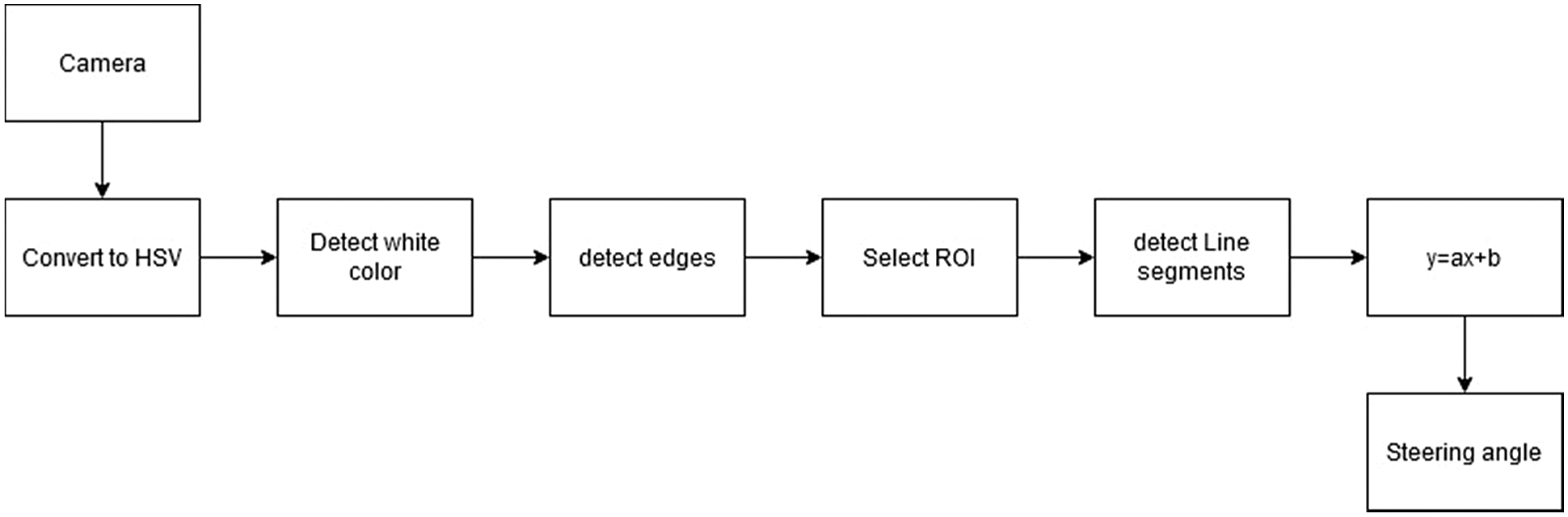
Figure 4: Steering angle (θ) calculation process
Camera
The camera will start recording a video with a resolution of 100 × 100 (Fig. 5). Since frames per second (fps) will drop after applying the processing techniques to each frame, we propose lowering the resolution to obtain a better fps.
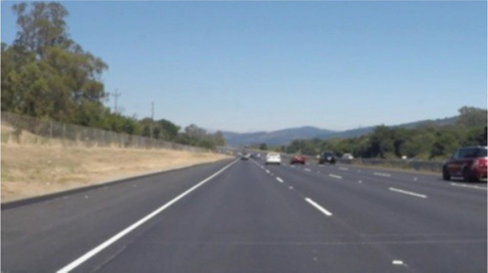
Figure 5: road line
hue saturation, value (HSV) color space conversion
After taking the video recording as frames from the camera, the following step is to convert each frame into an HSV color space (Fig. 6). The main benefit is that it helps you distinguish between colors based on their luminance levels [26].
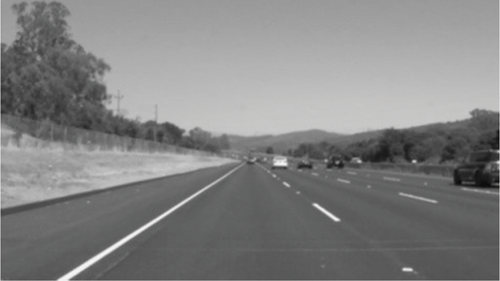
Figure 6: convert the image to HSV color
Detect white color and Edges
After converting the image to an HSV color space, we can now detect only the color we're interested in (i.e., white, since it is the color of the lane lines). Edges are only detected using canny edge detectors to minimize the overall distortion in each frame (Fig. 7) [26].
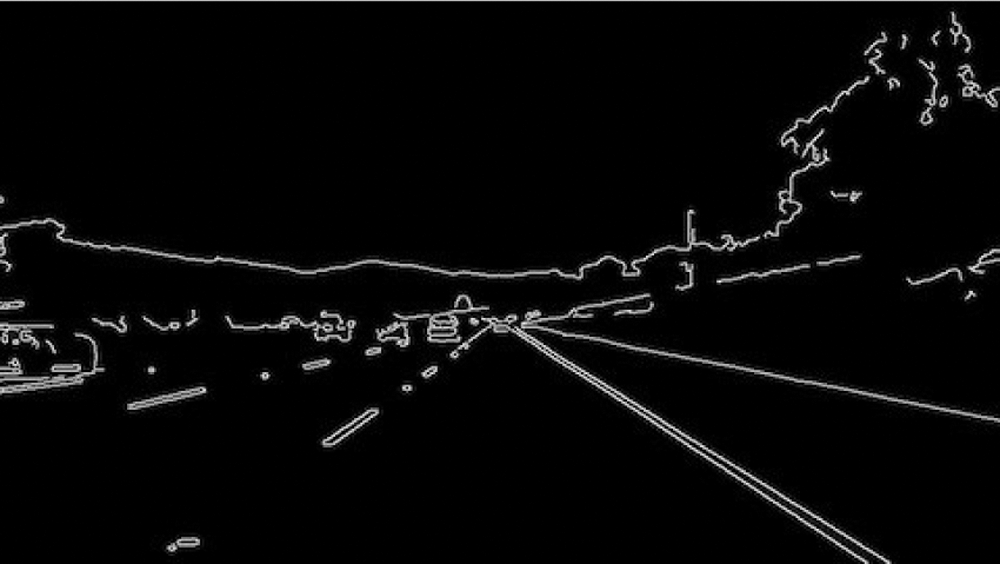
Figure 7: Canny edge detection
Select region of interest (ROI)
To concentrate only on one area of the picture, a ROI must be chosen. We do not want the robot car to see many things in the environment in this situation. We only focus on the lane lines in the bottom half of the frame and disregard the rest (Fig. 8) [26].
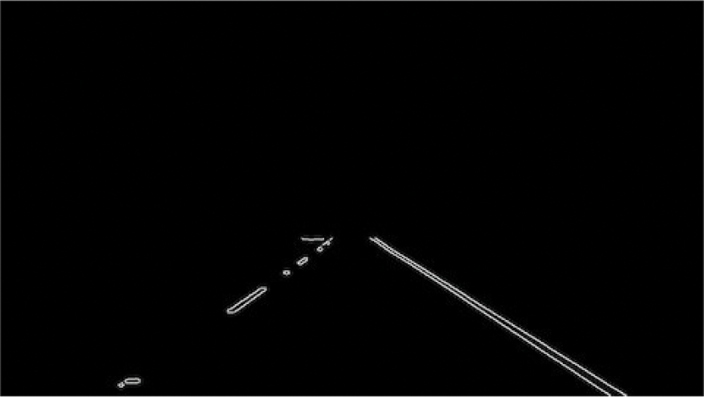
Figure 8: ROI selection
Detect line segments
The Hough transform technique is employed to find line segments from an edged frame (Fig. 9). The Hough transform is a mathematical technique for detecting any shape. It can recognize practically any object, even if it has been skewed by a certain number of votes [26].
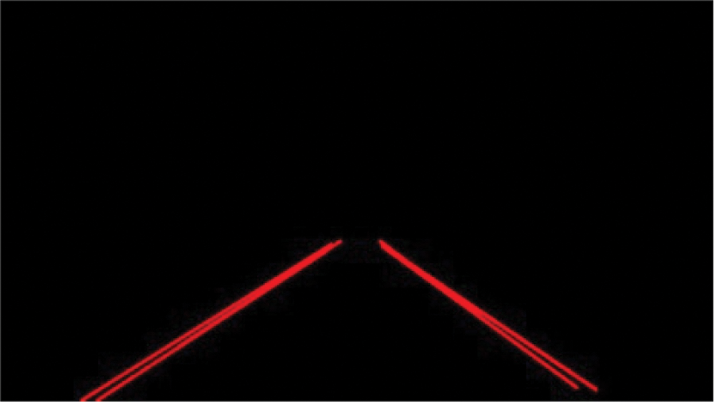
Figure 9: Identification of lane lines on the road
Average slope and intercept (m, b)
Here, the average of line segment slopes and intercepts identified using the Hough transform will be determined. Left lane points are defined as all lines with a negative slope; the right lane is the opposite. To improve detection accuracy, two boundary lines divide each picture into two sections (right and left). Right lane estimation is correlated with all width points greater than the right boundary line. If all width points are less than the left boundary line, they are linked to measuring the left lane (Fig. 10) [26].
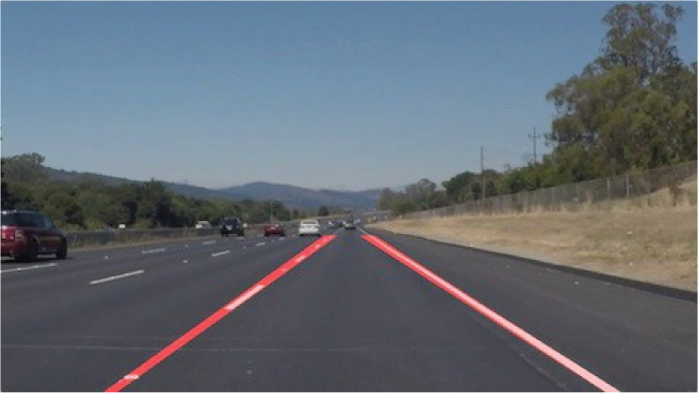
Figure 10: superimpose the left and right lines onto the original image
Calculate and display heading line
The heading line determines the direction in which the steering motor should rotate and the speed at which the throttling motors should run. If θ = 90°, the car can drive forward without having to steer. If θ > 90°, the car should turn right; otherwise, it should turn left.
3.2 Steering Angle Estimation Using CNN
When working with deep learning networks, data preparation is needed. The RPi captures images and data as the user drives the vehicle around the track at 4–5 km/h. Approximately 30,000 images are paired with steering angles in the data collected (Fig. 11). The image's initial resolution is 100 × 100 pixels.
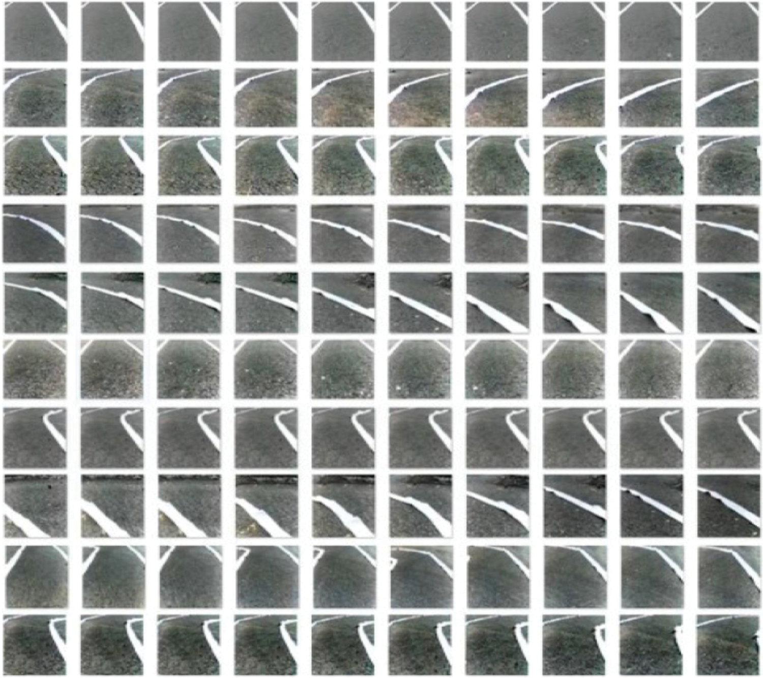
Figure 11: Collected data set
To avoid the blur caused by vibration as the vehicle drives on the track, the Pi Camera is set to capture at 10 fps with an exposure time of 5000 us. Fig. 12 provides several examples of this dataset's images.
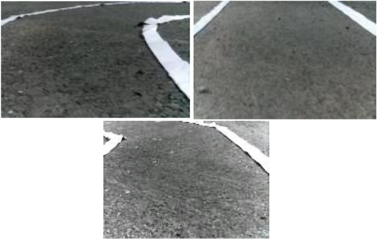
Figure 12: Samples from the driving dataset
Because there are too few examples to train on, deep learning models overfit the limited dataset, resulting in a model with poor generalization performance. Data augmentation manipulates incoming training data to produce more instances of training data by randomly converting existing examples into new ones. This approach expands the training size, reducing overfitting. Horizontal flip, brightness changes, random shadow, height, and width change are all common transformations. Furthermore, data augmentation is done only on the training data, not the validation or test data [27].
The dataset was divided into three subsets: training (60%), validation (20%) and test (20%). The training dataset contains 36,000 augmented frames, and the validation set contains 6000 frames. The model was copied back to the RPi after it was trained on the desktop computer. The vehicle's main controller then uses the model to feed a picture frame from the Pi camera as input. Each control cycle can process 10 images per second, and the vehicle's top speed around curves is 5–6 km/h.
3.2.4 Convolutional Neural Networks
CNNs is a powerful artificial neural network technique CNNs, are multilayer neural networks designed specifically for 2D input, such as video and pictures, and have become widely used in computer vision. These networks preserve the problem's spatial structure, make effective use of structural information and patterns in a picture and were designed for object identification and classification tasks [28].
CNNs get their name from the convolutional layers that make up its structure. Convolutional layers’ primary task is to detect specific local characteristics in each area of the input picture. A convolution layer is made up of a number of separate filters. The filter is slid over the entire image, and the dot product of the filter and chunks of the input image is calculated. Each filter is independently convolved with the image to produce feature maps. We can utilize a feature map for a variety of purposes, including reducing the size of an image while keeping its semantic content.
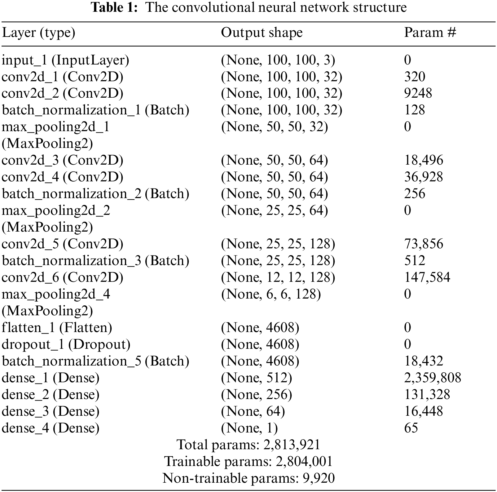
The network architecture comprises 18 layers, including 6 convolutional layers, and 4 fully connected ones. The input image is 100 × 100 × 3 (height × width × depth format). Convolutional layers were designed to perform feature extraction and were chosen empirically through a series of experiments with varied layer configurations. Convolutional layers use a 3 × 3 kernel and a stride of 2 × 2. The respective depth of each layer is 32, 32, 64, 64, 128, and 128 to push the network going deeper.
The max-pooling layer is a powerful tool used by CNN. This is a method that resizes large images but keeps the most important information about them. All max-pooling layers were chosen with a kernel of 2 × 2 and non-stride. The output is flattened after the convolutional layers, followed by a succession of fully connected layers of decreasing size: 512, 256, 64, and 1.
Batch normalization is a layer that allows the network's layers to learn more independently. It is used to normalize the output of the preceding layers and can be used as regularization to prevent the model from overfitting. By placing the BN after the rectified linear unit (ReLU) yields a slightly higher accuracy and lower loss.
All hidden layers are equipped with the ReLU to improve the convergence. From feature vectors, we apply Softmax to calculate steering wheel angle probability. The entire network will have ∼2,813,921 parameters (Tab. 1) and will offer excellent training performance on modest hardware. Additionally, to make the architecture more robust and avoid overfitting, we use batch normalization and dropout [28] at a rate of 0.5 for the last two fully connected layer gatherings of most parameters.
3.3 Proportional-Integral-Derivative Control
The PID constants were tuned separately in this cascaded PID method. A PID controller adjusts the output to keep the input variable close to the reference set-point. Three parameters can be tweaked to fine-tune this process (Kp, Ki, and Kd). Here is a continuous representation of the well-known PID controller equation.
Kp, Ki, and Kd represent the proportional, integral, and derivative gain constants, respectively.
To implement the controller equation in digital form, the reverse Euler method for numerical integration is employed.
u(kT) and e(kT) present the discrete time control and error signals at T sampling time.
The PID regulates both the left and right motor speeds based on the expected error measurement. The PID controller generates a control signal to establish the left and right speeds of the robot wheels (PID-value). It is a differential drive system.
The right and left speed used the duty cycle of the PWM and applied at the input pins of the motor driver IC.
The Ziegler–Nichols tuning method [29] was used to obtain the PID parameters (Kp, Ki, and Kd). To begin, the system's Ki and Kd were set to 0. The Kp was raised from 0 to the maximum gain Ku, after which the robot oscillated constantly (Tab. 2).
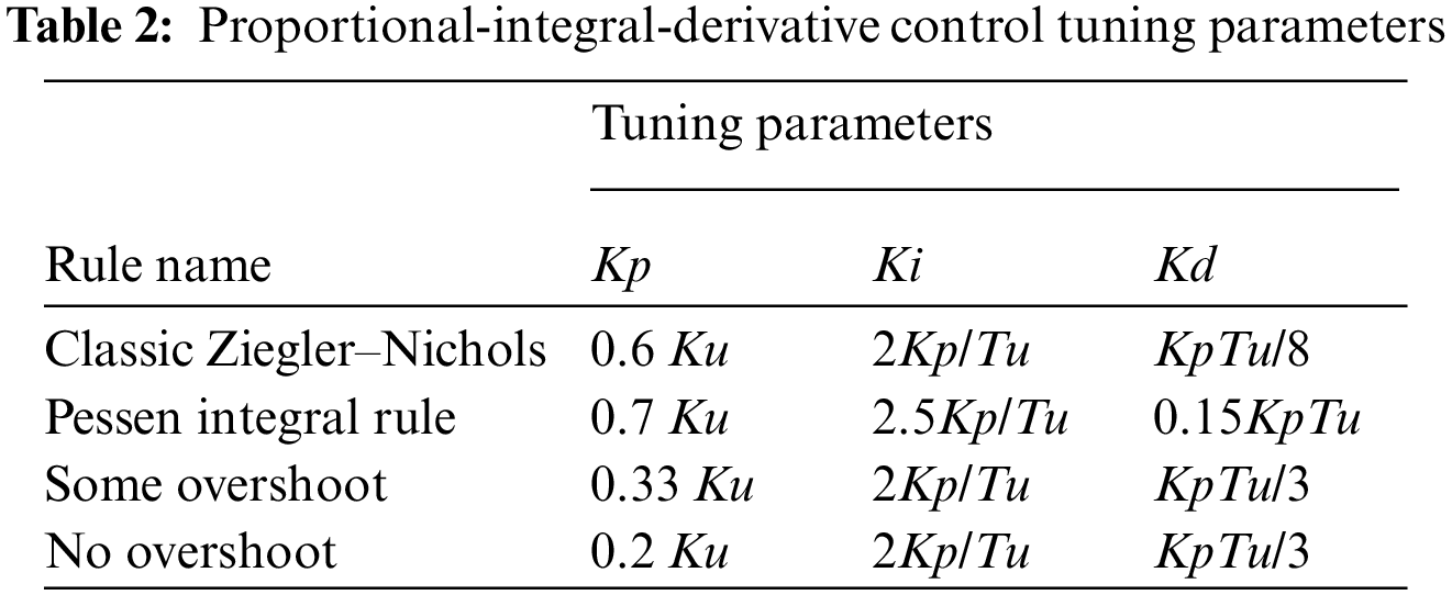
Because of the variations in line curvature, a traditional PID controller was found to be inadequate for the line-follower robot after extensive testing. To fix this problem, only the last three error numbers were summarized rather than aggregating all preceding values. The updated controller equation is as follows:
This technique provides satisfactory performance for lane detection.
We presented a vision navigation autonomous robot in which a camera takes an image input and a CNN model is employed to take a decision accordingly. To provide a smooth tracking line, we designed a deep learning based cascade PID controllers. The results indicate that the suggested approach is well suited to autonomous robots, as they can operate with imprecise information. More advanced controllers based deep learning could be developed in the future.
Acknowledgement: The authors acknowledge the support of King Abdulaziz City of Science and Technology.
Funding Statement: The authors received no specific funding for this study.
Conflicts of Interest: The authors declare that they have no conflicts of interest to report regarding this study.
1. C. Thorpe, M. Herbert, T. Kanade and S. Shafter, “Toward autonomous driving: The cmu navlab,” IEEE Expert, vol. 6, no. 4, pp. 31–42, 1991. [Google Scholar]
2. A. Broggi, M. Bertozzi and A. Fascioli, “Argo and the millemiglia in automatico tour,” IEEE Intelligent Systems and Their Applications, vol. 14, no. 1, pp. 55–64, 1999. [Google Scholar]
3. R. Gregor, M. Lutzeler, M. Pellkofer, K. Siedersberger and E. D. Dickmanns, “EMS-Vision: A perceptual system for autonomous vehicles,” IEEE Transactions on Intelligent Transportation Systems, vol. 3, no. 1, pp. 48–59, 2002. [Google Scholar]
4. A. Krizhevsky, I. Sutskever and G. E. Hinton, “ImageNet classification with deep convolutional neural networks,” Advances in Neural Information Processing Systems, vol. 1, pp. 1097–1105, 2012. [Google Scholar]
5. M. Andrychowicz, B. Baker, M. Chociej, R. Jozefowicz, B. McGrew et al., “Learning Dexterous In-Hand Manipulation,” CoRR, vol. abs/1808.00177, August 2018. [Online]. Available: https://arxiv.org/abs/1808.00177. [Google Scholar]
6. V. Nath and S. E. Levinson, Autonomous Robotics and Deep Learning, Springer International Publishing: London, Springer, pp. 1–3, 2014. [Google Scholar]
7. R. K. Bhadani, J. Sprinkle and M. Bunting, “The cat vehicle testbed: A simulator with hardware in the loop for autonomous vehicle applications,” arXiv preprint arXiv:1804.04347, 2018. [Google Scholar]
8. M. Masmoudi, H. Friji, H. Ghazzai and Y. Massoud, “A reinforcement learning framework for video frame-based autonomous Car-following,” IEEE Open Journal of Intelligent Transportation Systems, vol. 2, pp. 111–127, 2021. [Google Scholar]
9. A. Ndikumana, N. H. Tran, D. H. Kim, K. T. Kim and C. S. Hong, “Deep learning based caching for self-driving cars in multi-access edge computing,” IEEE Transactions on Intelligent Transportation Systems, vol. 22, no. 5, pp. 2862–2877, 2021. [Google Scholar]
10. P. Cai, H. Wang, H. Huang, Y. Liu and M. Liu, “Vision-based autonomous Car racing using deep imitative reinforcement learning,” IEEE Robotics and Automation Letters, vol. 6, no. 4, pp. 7262–7269, 2021. [Google Scholar]
11. A. Chowdhury, G. Karmakar, J. Kamruzzaman and S. Islam, “Trustworthiness of self-driving vehicles for intelligent transportation systems in industry applications,” IEEE Transactions on Industrial Informatics, vol. 17, no. 2, pp. 961–970, 2021. [Google Scholar]
12. F. Yu, Z. Qin, C. Liu, D. Wang and X. Chen, “REIN the RobuTS: Robust DNN-based image recognition in autonomous driving systems,” IEEE Transactions on Computer-Aided Design of Integrated Circuits and Systems, vol. 40, no. 6, pp. 1258–1271, 2021. [Google Scholar]
13. F. Farbord, Autonomous Robots, Boston, Springer International Publishing, pp. 1–13, 2020. [Google Scholar]
14. R. Siegwart and I. R. Nourbakhsh, Introduction to Autonomous Mobile Robots, A Bradford Book, Cambridge, The MIT Press, pp. 11–20, 2004. [Google Scholar]
15. M. Bojarski, D. D. Testa, D. Dworakowski, B. Firner, B. Flepp et al., “End to end learning for self-driving cars,” CoRR, vol. abs/1604.07316, 2016. [Online]. Available: http://arxiv.org/abs/1604.07316. [Google Scholar]
16. B. T. Nugraha, S. Su and S. T. Fahmizal, “Towards self-driving car using convolutional neural network and road lane detector,” in 2017 2nd Int. Conf. on Automation, Cognitive Science, Optics, Micro Electro-Mechanical System, and Information Technology (ICACOMIT), Jakarta, Indonesia, pp. 65–69, 2017. [Google Scholar]
17. V. John, Z. Liu, S. Mita, C. Guo and K. Kidono, “Real-time road surface and semantic lane estimation using deep features,” Signal Image Video Process, vol. 12, pp. 1133–1140, 2018. [Google Scholar]
18. D. Xiao, X. Yang, J. Liand, M. Islam, “Attention deep neural network for lane marking detection,” Knowledge Based Systems, vol. 194, pp. 105584, 2020. [Google Scholar]
19. Turtlebot3, 2022. [Online]. Available: https://www.turtlebot.com/. [Google Scholar]
20. Donkey car, 2022. [Online]. Available: https://www.donkeycar.com/. [Google Scholar]
21. Dfrobot, 2022. [Online]. Available: https://www.dfrobot.com/. [Google Scholar]
22. D. Janglova, “Neural networks in mobile robot motion,” International Journal of Advanced Robotic Systems, vol. 1, pp. 15–22, 2004. [Google Scholar]
23. M. Duong, T. Do and M. Le, “Navigating self-driving vehicles using convolutional neural network,” in Int. Conf. on Green Technology and Sustainable Development (GTSD), Ho Chi Minh City, pp. 607–610, 2018. [Google Scholar]
24. Y. Nose, A. Kojima, H. Kawabata and T. Hironaka, “A study on a lane keeping system using CNN for online learning of steering control from real time images,” in 34th Int. Technical Conf. on Circuits/Systems, Computers and Communications (ITC-CSCC), JeJu, Korea (Southpp. 1–4, 2019. [Google Scholar]
25. Na Yong-Kyun and Oh Se-Young, “Hybrid control for autonomous mobile robot navigation using neural network-based behavior modules and environment classification,” Autonomous Robots, vol. 15, pp. 193–206, 2003. [Google Scholar]
26. J. Howse and J. Minichino, Learning OpenCV 4 Computer Vision with Python 3: Get to grips with tools, techniques, and algorithms for computer vision and machine learning, pp. 40–80, Packt Publishing, 2020. [Online]. Available: https://www.amazon.com/Learning-OpenCV-Computer-Vision-Python/dp/1789531616 [Google Scholar]
27. M. Hodnett and J. F. Wiley, R Deep Learning Essentials, pp. 21–25, 2018. [Online]. Available: https://www.oreilly.com/library/view/r-deep-learning/9781788992893/ [Google Scholar]
28. U. Michelucci, Advanced Applied Deep Learning: Convolutional Neural Networks and Object Detection, New York, Apress, pp. 55–77, 2020. [Google Scholar]
29. Y. Pan, X. Li and H. Yu, “Efficient PID tracking control of robotic manipulators driven by compliant actuators,” IEEE Transactions on Control Systems Technology, vol. 27, no. 2, pp. 915–922, 2019. [Google Scholar]
 | This work is licensed under a Creative Commons Attribution 4.0 International License, which permits unrestricted use, distribution, and reproduction in any medium, provided the original work is properly cited. |