DOI:10.32604/cmc.2022.020879
| Computers, Materials & Continua DOI:10.32604/cmc.2022.020879 | |
| Article |
Thermomechanical Behavior of Brake Drums Under Extreme Braking Conditions
1Institute of Science and Technology, University Center Salhi Ahmed Naama, Algeria
2Laboratory of Gas Combustion and Environment, University of Sciences and Technology of Oran, L.P 1505 El-Menaouer, Oran, USTO 31000, Algeria
3High School of Aeronautic Techniques Dar El Beida, Algeria
4Ho Chi Minh City Open University, Ho Chi Minh City, Viet Nam
5Faculty of Engineering, Van Lang University, Ho Chi Minh City, Vietnam
6Soete Laboratory, Faculty of Engineering and Architecture, Ghent University, TechnologieparkZwijnaarde 903, B-9052 Zwijnaarde, Belgium
*Corresponding Author: M. Abdel Wahab. Email: magd.a.w@vlu.edu.vn; magd.abdelwahab@UGent.be
Received: 12 June 2021; Accepted: 30 December 2021
Abstract: Braking efficiency is characterized by reduced braking time and distance, and therefore passenger safety depends on the design of the braking system. During the braking of a vehicle, the braking system must dissipate the kinetic energy by transforming it into heat energy. A too high temperature can lead to an almost total loss of braking efficiency. An excessive rise in brake temperature can also cause surface cracks extending to the outside edge of the drum friction surface. Heat transfer and temperature gradient, not to forget the vehicle's travel environment (high speed, heavy load, and steeply sloping road conditions), must thus be the essential criteria for any brake system design. The aim of the present investigation is to analyze the thermal behavior of different brake drum designs during the single emergency braking of a heavy-duty vehicle on a steeply sloping road. The calculation of the temperature field is performed in transient mode using a three-dimensional finite element model assuming a constant coefficient of friction. In this study, the influence of geometrical brake drum configurations on the thermal behavior of brake drums with two different materials in grey cast iron FG200 and aluminum alloy 356.0 reinforced with silicon carbide (SiC) particles is analyzed under extreme vehicle braking conditions. The numerical simulation results obtained using FE software ANSYS are qualitatively compared with the results already published in the literature.
Keywords: Drum brake; finite element method; braking energy distribution; friction heat power; friction heat flux; transient temperature field
The thermal behavior phenomena have been studied widely in different fields, as presented in References [1–3]. In addition to their basic function, friction brakes present the thermal problem of transforming the kinetic energy of the moving parts of the vehicle into thermal energy [4]. This energy conversion process has been and is the subject of extensive experimental and numerical investigations on the thermal properties of brakes in international automotive research [5]. The focus is on the relationship between the heat released by the friction couples under the effect of external mechanical loads and the stresses and deformations of the components due to the heat generated. This interdependence has significant consequences on the function and load capacity of the brake system components. The analysis of thermal conditions, in particular in friction bodies (brake drum, brake linings…), the evaluation of friction surface temperatures as well as temperature fields in friction bodies and the knowledge of thermal load limits, heat absorption capacity, heat transfer to air and heat transfer to adjacent components allow a thermal optimization of brake components. Combined with the mathematical validation of stresses and deformations under mechanical load, the knowledge acquired provides an important basis for an optimized design in terms of the efficiency and material economy of the brakes. Drum brakes seem to last longer in the heavy-duty vehicle sector than in the passenger automobile sector because the advantages of the drum brake are more evident. This is not only due to the low actuating forces resulting from the higher self-reinforcement, but rather to lower manufacturing costs, longer maintenance intervals and the generally longer service life of the linings. It should be noted that under identical conditions, drum brakes attain lower temperatures than disk brakes. Today, more than 90% of heavy-duty vehicles are equipped with S-cam simplex pneumatic drum brakes for a fixed application force [6]. An analytical solution to compute the three-dimensional of distribution of temperature in a solid subjected to a moving rectangular heat source with surface cooling was proposed [7]. Moreover, a coupled numerical-experimental approach to identifying critical thermomechanical loadings of truck brake discs was presented [8]. Furthermore, the distribution of the normal pressure between the drum and brake linings, their deformations and their effective stresses was investigated using analytical and FEM [9]. The authors observed that high contact forces were present at the top end of the lining, particularly on the rear shoe and maximal stresses at the shoes were higher than those of the drum. Moreover, tribological, thermal and mechanical coupling aspects of dry sliding contact were presented [10]. In this research work, grey cast iron was replaced by an aluminum alloy to reduce the weight of the drum and also to improve the thermal dissipation rate of the brake drum. It was therefore decided to carry out investigations on the effect of geometric design and materials in order to evaluate and compare the thermal behavior in transient mode of different configurations of heavy-duty brake drums. All brake drum variants were modelled in three-dimensional configurations. To simulate the convective heat transfer rate, CFD analyses using ANSYS fluid software was performed. The numerical simulation results obtained using FE software ANSYS are qualitatively compared with the results already published in the literature.
2.1 Friction Heat Power and Heat Input Flow
The dynamic behavior of the braking system is modelled in order to be able to determine the braking power developed in a drum brake. The braking forces on the front and rear wheels resulting from the friction forces of the brake drums are in opposite directions to the vehicle movement, as shown in Fig. 1. Based on the law of energy conservation, the braking work

Figure 1: Longitudinal forces acting on the vehicle during braking on a downhill
Kinetic energy
The work of the resistant forces acting on the vehicle is equal to:
From the above equations, it follows:
By deriving Eq. (1) with respect to time, we obtain the friction power dissipated during braking:
Taking into account the brake power distribution of the vehicle, expressed by
When the wheel closes to lock the braking condition, the tires will have a certain amount of the slip rate (s); a part of the friction heat will be converted to friction heat between the tire and the road. The optimal value of the slip rate is between 0.05 and 0.20 [11]. In this study, only the front brakes were chosen because they are the most heavily loaded. The braking power dissipated in each front brake is split between the brake drum and the two brake linings:
During stopping braking, the drums absorb about 95% of the heat, and the brake shoes 5%. The relation (8) is available when the contact between drum and linings is of a short time, i.e., when the sliding velocity is high. Eq. (7) shows that the braking power with motor brake action required to bring a vehicle to a given speed depends directly on the vehicle's weight, rotating masses initial speed, deceleration, slope, road conditions, rolling coefficient air resistance, tire slip factor, heat distribution rate and the contact surface between the brake lining and the brake drum.
Another important thermal factor is the efficiency with which the braking system converts the movement of the brake drum into heat and, therefore, the dissipated heat rapidity by the brake. Note that disc brakes are entirely exposed to the surrounding atmosphere, and drum brakes are completely enclosed within the brake assembly. This can result in a relatively higher temperature compared to the disc brake system under the same braking conditions. The high temperature of the drum brake shoes can cause the brake to fade and eventually lose its effectiveness. The discoloration is the result of too much heat accumulation in the drum [12–14]. Drum brakes can therefore only operate as long as they can absorb the heat generated by the kinetic energy lost due to wheel deceleration. Once the brake components themselves are saturated with heat, they lose the ability to stop a vehicle. Eq. (10) can be applied to any braking situation and road conditions. There are two aim braking situations, stop braking and deceleration braking on the flat or sloped road. In the first case, the final speed is zero (
2.2 Governing Heat Dissipation Equations
During the braking process, the friction heat released in the drum brake is dissipated in two different ways: in both bodies in contact by conduction and accumulation in the materials and in the environment by convection and radiation. Thermal conduction exists between the drum and the brake linings because the friction interface generates heat. As already mentioned above, the distribution of the heat generated on contact between the two different friction materials is unequal because the thermal properties of the two components are different. This heat distribution is described by the heat flow distribution coefficient α, which is determined for the temperatures achieved on the two contact surfaces. It defines the proportion of heat flow absorbed by the brake drum. The relations (8) and (9) will calculate this factor in the case of perfect contact. At the interface, it is assumed that the temperatures are the same [15]. developed a thermal model based on the finite difference method and concluded that 65% of the energy is dissipated by convection and 35% as stored thermal energy, energy lost by radiation and conduction to the lining. For transient thermal brake drum analysis, the heat conduction for homogeneous and isotropic material with no internal heat production is governed by the following differential equation:
Thermal radiation is related to the temperatures of the drum's outer surface; the higher the temperature, the greater the heat dissipation by thermal radiation. In general, the heat dissipated by thermal radiation is about 5%–10% of the total heat dissipated. Thermal radiation only has an important role at high temperature and low velocities. The radiation heat dissipation is defined by:
The heat flow balance in the brake drum can be written as follows:
2.3 Thermal Modelling of Brake Drums
2.3.1 Geometrical Models and Mesh of Brake Drums
A complete three-dimensional structure of the drum brake has to be modelled. Three-dimensional models of the brake drums were built using the commercial simulation software ANSYS. The axisymmetric condition has been considered for the geometrical modelling and numerical simulation of the thermomechanical behavior of the brake drums. In order to evaluate and optimize the thermomechanical behavior of the brake drums and the heat release efficiency, four models are selected with the exact main dimensions, a basic brake drum, a brake drum with a groove on the front face, a drum with a circumferential fin and a drum with longitudinal fins, see Fig. 2.

Figure 2: The selected 3D geometrical models of the brake drum
A three-dimensional structure of each drum brake model, composed of the drum, head pad and tail pad, must be modeled in 3D finite-element. For solid modeling, three-dimensional isoparametric tetrahedral elements with 10 nodes are used, which are appropriate for the analysis of the transient thermal flow in a circular axisymmetric structure. It is assumed that the connection between the lining and the shoe is uniform. This condition also applies to the contact areas between linings and drum. Fixed bolts are modeled using cylindrical support elements. The brake shoes can then rotate around the fixed bolts see Fig. 3. In the models, the S-cam clamping device is not neglected; but it is only substituting by the acting force and thus shoe pressure. Meshing does influence not only the solution accuracy but also the convergence. The choice of mesh type is made according to the geometry and the physical problem to be resolved.

Figure 3: FE model of the drum-linings-shoes assembly and boundary conditions
The chosen simulation conditions of the thermal behavior analysis of a truck brake drum are presented in Tab. 1. Figs. 3 and 4 show the FE model of the drum-linings-shoes assembly with boundary conditions and isoparametric tetrahedral mesh with ten nodes of the four selected drum models. The mesh parameters for these drum models are listed in Tab. 2.
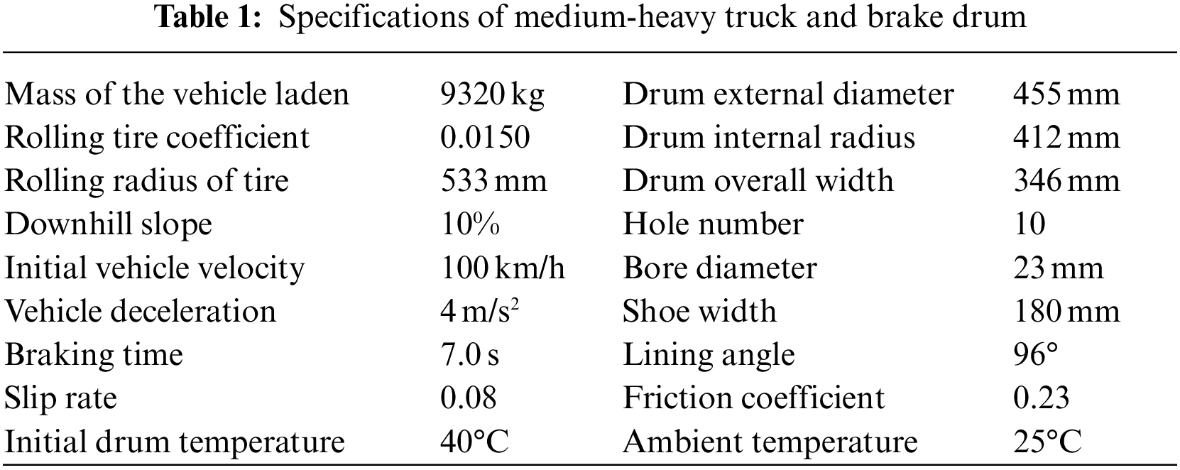

Figure 4: Isoparametric tetrahedral mesh with 10 nodes of four analyzed drum models

2.3.2 Material Properties of all Drum Brake Components
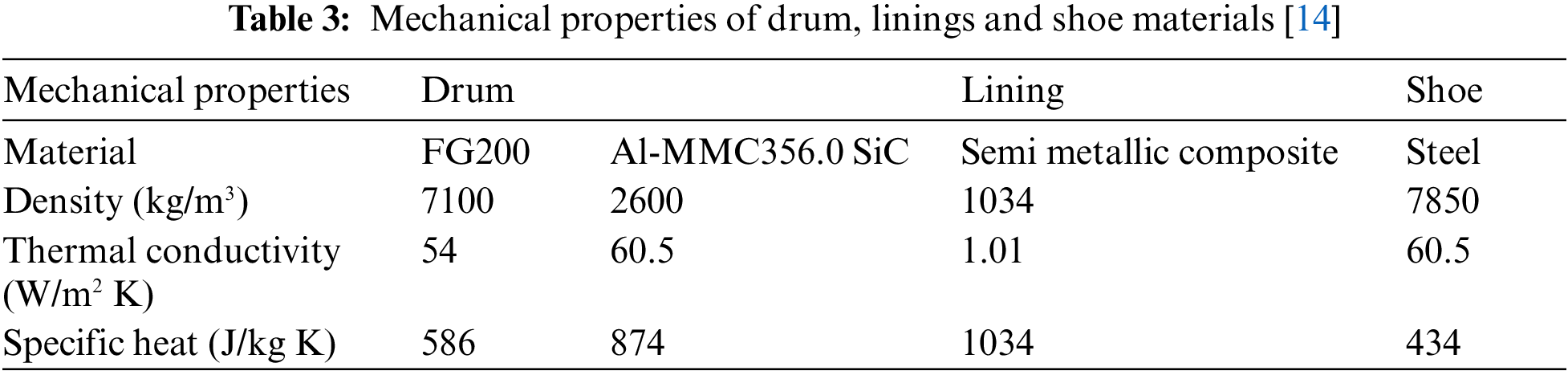
The brake drums as brake discs must be manufactured with a material that favors their thermal resistance with a high friction coefficient to generate the required friction force [16,17]. The drum materials are supposed homogeneous and isotropic. The brake drum is often made of cast iron, although some vehicles use aluminum drums, especially for the front wheels. Aluminum conducts heat better than cast iron, which improves heat dissipation and reduces fading. Aluminum drums are lighter than cast iron drums. Since Al MMC wears more easily than iron, Al MMC drums often have a cast iron or steel coating on the inner surface of the drum, which is glued or riveted to the outer shell. Tab. 3 gives the mechanical properties of the drum, linings and shoe materials considered in this work.
3 Simulation Results and Discussions
3.1 Convection Heat Coefficient of Each Drum Model
In the thermal modeling of the four selected brake drum models, the convection coefficient h = h (A, t) of each heat exchange area of the drum is first computed using the ANSYS CFX software. ANSYS CFX Preprocessor imports the mesh generated of the domains and defines the flow physics, the border states and the parameters of the SOLVER module. All problem specifications produced in the ANSYS CFX-Pre-module are solved by ANSYS CFXSolver. To compute the heat transfer coefficient of each convective surface and at each time, the solver uses the following relation [18]:

Figure 5: Full and portion drum model in CFX and boundary conditions. Fluid domain: ambient temperature at 25°C, reference pressure is 1 atm, thermal energy model; Solid domain: initial drum temperature at 40°C, brake drum with variable angular velocity
Fig. 6 shows the variation of convection coefficient distribution in each brake drum model at different times. This is indeed the average convection coefficient of all heat exchange surfaces. It is noted that for the reference model N°1, Figs. 6 and 7, the convection coefficient of the drum's inner free face (4) has a maximum value greater than 170 W/m² K and this surface keeps a relatively higher value, equal to 24 W/m² K, compared to the other faces even at the end of the brake. The convective heat dissipation on the drum's inner free face (4) is not efficient, because the airflow goes through a sudden geometrical change, which results in air turbulence. It is also observed that convection heat transfer decreases with braking time. The convection coefficient on the drum face (5) has a maximum value of 107 W/m² K. The drum of model N°2 has 72 longitudinal fins on its peripheral surface (5), thus increasing the heat exchange surface, Figs.6 and 7. On this modified face, the average convection coefficient reaches a maximum value of 135 W/m² K greater than of the corresponding area of the reference drum (HTC = 107 W/m² K). The addition of longitudinal fins contributes significantly to the improvement of convection heat dissipation. As in the case of the previous brake drum, the average convection coefficient on the face (4) reaches at the braking begin its maximum value of 193.47 and 20 W/m² K at the end of braking. In Figs. 7–10, we have another drum model having on the inner free surface (1) a circular groove with a curved profile that not only increases the heat exchange area but also improves the airflow with less turbulence. In Fig. 10, it can be seen that the average convection coefficient of the face (1) of the circular groove reaches a maximum value of 253 W/m² K at the beginning of braking and 36.44 W/m² K at the end of the braking process. The two previous models studied have not been achieved such a high value of the heat exchange coefficient. The groove on this part of the drum has significantly improved the convection coefficient of the entire heat exchange surface, and consequently, the heat dissipation. Note that the outer face (2) adjacent to the front face has a slightly curved profile, also contributing to the improvement of airflow and at the same time to a slight increase in the heat exchange surface. In this modified model, only faces contributing to convection heat exchange were considered, as shown in Fig. 10. As shown in Figs. 7–10, the circular groove and the slightly curved profile of the face (2) on this modified drum model have significantly improved the convection coefficient of the entire heat exchange surface.

Figure 6: Visualization of heat transfer coefficient (HTC) evolution with HTC maximal value vs. time of three selected drum models

Figure 7: HTC-variation on the faces of model N°1 (reference drum)

Figure 8: HTC-variation on the faces of model N°2 (finned drum)

Figure 9: HTC-variation on the faces of model N°3 (grooved drum)

Figure 10: Predicted temperature of the four FG200 brake drum models versus braking time
3.2 Transient Temperature Distribution of Each Drum Model
3.2.1 Influence of the Geometrical Model
For thermal modelling, we consider the drum lining and clamps assembly, although we only want to determine the drum's temperature field. Thus, an indirect coupling of the thermal and mechanical model will be carried out, which implies that the brake shoes must be considered in the geometry to be able to take into account the pressure applied on the drum. The drum rotates around cylindrical support with a decreasing variable rotational velocity. Each brake shoe is fixed to a cylindrical bolt having one degree of freedom to transmit the force applied at the other end. A time-varying heat flow will be introduced to each drum-to-lining contact area. ANSYS-software will first solve the thermal problem and then the mechanical problem by exploiting the thermal results. The same mesh as in the CFX simulation will be used. For the determination of the temperature field, a transient thermal simulation is performed in ANSYS-Workbench. The parameters of this simulation are the total simulation time (

Figure 11: Predicted temperature distribution of FG20 brake drum for different models at two other braking times
The brake drum temperature evolution over time of the four models is shown in Fig. 10. The initial point of intersection in the graphs showed that the models were investigated at the same initial temperature of the brake drum, Fig. 11. The temperature of the four models has increased from the initial (minimum) temperature to their maximum temperature after an intermediate braking time of 3.6 s and then begins to decrease until the braking end. After a braking time from zero to 3.64 s, the temperature of the reference FG20 drum model N°1 increases and reaches its maximum of 586.90°C. From this moment until the end of braking, the temperature begins to decrease to 457°C. After the braking end, the temperature variation with time becomes less important, from 457°C to 353°C. All three modified models record a rate of temperature decrease compared to the reference model, Figs. 10 and 11. This shows that the heat dissipation rate of the modified models is higher than that of the reference model. Therefore, a quantity of heat tends to remain inside the wall of the reference brake drum model due to the low heat transfer. This retained heat is the main cause of the thermal problems of the brake drum system mentioned above. The temperature difference between the modified ventilated brake drum and the reference brake drum is about 43°C. This showed that the ventilated brake drum model dissipates more heat than the reference brake. Drum. With the drum model N°3, the temperature difference is more significant; it is about 61°C. It should be noted that the temperature drop between the maximum and minimum values is more significant (ΔT = 102°C), which means that we have better heat dissipation during braking time, Figs. 10 and 11. For the drum model N°4 with circular fin, the temperature difference compared to the reference drum becomes even higher; it is about 63°C. This demonstrates the significant effect of the circular fin on the heat dissipation of the brake drum. In Figs. 10 and 11, we can see that at intermediate single braking time the high thermal stresses on the friction area of all models are practically comparable to those resulting from fade tests with repeated braking from a high initial speed.
3.2.2 Influence of Brake Drum Material
The temperature field in the brake drum has been computed for two different materials, namely FG200 grey cast iron and 356.0 SiC aluminum alloy. 2. Fig. 12 shows the predicted maximal temperature at intermediate and end of braking times, respectively of FG200 and aluminum alloy brake drum for the four investigated models. Fig. 12 illustrates the advantage of choosing the drum material over the thermal behavior of the brake drum, and this is independently of the braking time. With the basic model N°1, the effect of the Al-MMC material of the brake drum is positive. A temperature reduction between 7% and 17% can be achieved compared to the grey cast iron drum. With model N°4, a temperature reduction of 22% can be realized at an intermediate braking time and 7% at the end of the braking process. With the model N°3, we have a reduction between 21% and 26%.

Figure 12: Predicted maximal temperature at intermediate and end of braking times of FG200 and aluminum alloy brake drum for four models
This study showed the positive effect of some practical measures on improving the heat dissipation of a heavy vehicle brake drum. The thermal energy stored in the reference brake drum model is the main cause of brake drum thermal problems. It should be noted that extreme braking conditions such as initial braking speed, vehicle load, braking on a steep slope result in very high drum temperatures that exceed the allowable temperatures. These high temperatures cause brake fading and therefore an undesired loss of brake performance and a significant increase in braking distance. In addition, excessive heat transferred to the brake fluid can even lead to its evaporation. The addition of longitudinal or circumferential fins on the modified brake drums has contributed significantly to the improvement of heat dissipation and structural strength without changing the initial main geometric dimensions of the original brake drum model. The simulation results obtained with the modified brake drum models can be used to orient automotive engineers in the development of other, more efficient brake drum models. The results obtained from the numerical simulation of the different brake drum models are similar to those of the previous comparable models studied. The absolute maximum drum temperature was reached at mid-point of the braking time, regardless of the model variant studied. The introduction of ventilation fins has favored heat transfer by convection and, therefore, the drum brake cooling. The temperature difference between a basis drum and a modified drum with longitudinal ventilation fins reached a value of 43°C at intermediate braking time, a decrease of 7%. This temperature difference is even higher with a circumferential finned drum in the order of 55°C, a reduction of 9.5%. This theoretical study also showed that the choice of brake drum material significantly influences the thermal behavior of the brake drum. Al MMC brake drums have a better thermal braking behavior than those made of grey cast iron. As a general conclusion, it is always possible to improve the brake drums’ thermal behavior and thereby avoid brake fading by modifying the aerodynamic design and the size of the original model and choosing the appropriate drum material.
Acknowledgement: The authors acknowledge the financial support of University Center Salhi Ahmed Naama, Algeria. The authors wish to express their gratitude to Van Lang University, Vietnam for financial support for this research.
Funding Statement: The authors acknowledge the financial support of University Center Salhi Ahmed Naama, Algeria and Van Lang University, Vietnam for financial support for this research.
Conflicts of Interest: The authors declare that they have no conflicts of interest to report regarding the present study.
1. K. Antar, K. Amara, S. Benyoucef, M. Bouazza and M. Ellali, “Hygrothermal effects on the behavior of reinforced-concrete beams strengthened by bonded composite laminate plates,” Structural Engineering and Mechanics, vol. 69, no. 3, pp. 327–334, 2019. [Google Scholar]
2. M. Vinyas and S. Kattimani, “A finite element based assessment of static behavior of multiphase magneto-electro-elastic beams under different thermal loading,” Structural Engineering and Mechanics, vol. 62, no. 5, pp. 519–535, 2017. [Google Scholar]
3. M. Vinyas and S. Kattimani, “Static behavior of thermally loaded multilayered magneto-electro-elastic beam,” Structural Engineering and Mechanics, vol. 63, no. 4, pp. 481–495, 2017. [Google Scholar]
4. M. Djafri, M. Bouchetara, T. Khatir, S. Khatir and M. A. Wahab, “Calculation of the braking temperature on a brake disc of light passenger aircraft using FEM and newcomb models,” International Journal of Computational Methods, vol. 18, no. 5, pp. 2040002, 2021. [Google Scholar]
5. M. Djafri, M. Bouchetara, C. Busch and S. Weber, “Experimental study of the tribological behaviour of materials of brake disc and pads,” Mechanics, vol. 20, no. 4, pp. 420–425, 2014. [Google Scholar]
6. A. J. Day, “Braking of road vehicles,” Butterworth-Heinemann, 2014. [Online]. Available: https://www.sciencedirect.com/book/9780123973146/braking-of-road-vehicles?via=ihub=. [Google Scholar]
7. T. Osman, and A. Boucheffa, “Analytical solution for the 3D steady state conduction in a solid subjected to a moving rectangular heat source and surface cooling,” Comptes Rendus Mecanique, vol. 337, no. 2, pp. 107–111, 2009. [Google Scholar]
8. M. Collignon, A. -L. Cristol, P. Dufrénoy, Y. Desplanques and D. Balloy, “Failure of truck brake discs: A coupled numerical–experimental approach to identifying critical thermomechanical loadings,” Tribology International, vol. 59, pp. 114–120, 2013. [Google Scholar]
9. C. Hohmann, K. Schiffner, K. Oerter and H. Reese, “Contact analysis for drum brakes and disk brakes using ADINA,” Computers & Structures, vol. 72, no. 1–3, pp. 185–198, 1999. [Google Scholar]
10. D. Majcherczak, P. Dufrenoy and Y. Berthier, “Tribological, thermal and mechanical coupling aspects of the dry sliding contact,” Tribology International, vol. 40, no. 5, pp. 834–843, 2007. [Google Scholar]
11. M. Mitschke and H. Wallentowitz, Vehicle Dynamics (Dynamik der Kraftfahrzeuge), Berlin, Heidelberg, New York: Springer-Verlag, 2004. [Google Scholar]
12. A. Anderson and R. Knapp, “Hot spotting in automotive friction systems,” Wear, vol. 135, no. 2, pp. 319–337, 1990. [Google Scholar]
13. Z. Barecki and S. Scieszka, “Geometry of contact between brake shoes and drum,” SA Mechanical Engineer, vol. 34, no. 9, pp. 324–329, 1984. [Google Scholar]
14. W. Zhao and P. Zagrodzki, “Study of wet friction material test under severe thermal and mechanical loading (“Bump test”),” Journal of Tribology, vol. 123, no. 1, pp. 224–229, 2001. [Google Scholar]
15. R. N. Noyes and P. T. Vickers, “Prediction of surface temperatures in passenger car disc brakes,” SAE Transactions, pp. 1653–1658, 1969. [Google Scholar]
16. M. Djafri, M. Bouchetara, C. Busch, S. Khatir, T. Khatir et al., “Influence of thermal fatigue on the wear behavior of brake discs sliding against organic and semimetallic friction materials,” Tribology Transactions, vol. 61, no. 5, pp. 861–868, 2018. [Google Scholar]
17. M. Djafri, M. Bouchetara, C. Buschand, S. Weber, “Effects of humidity and corrosion on the tribological behaviour of the brake disc materials,” Wear, vol. 321, pp. 8–15, 2014. [Google Scholar]
18. A. Nejat, M. Aslani, E. Mirzakhalili and R. N. Asl, “Heat transfer enhancement in ventilated brake disk using double airfoil vanes,” Journal of Thermal Science and Engineering Applications, vol. 3, no. 4, pp. 045001, 2011. [Google Scholar]
19. C. Galindo-Lopez and M. Tirovic, “Understanding and improving the convective cooling of brake discs with radial vanes,” Proceedings of the Institution of Mechanical Engineers, Part D: Journal of Automobile Engineering, vol. 222, no. 7, pp. 1211–1229, 2008. [Google Scholar]
 | This work is licensed under a Creative Commons Attribution 4.0 International License, which permits unrestricted use, distribution, and reproduction in any medium, provided the original work is properly cited. |