DOI:10.32604/cmc.2022.024180
| Computers, Materials & Continua DOI:10.32604/cmc.2022.024180 | |
| Article |
Vehicle Positioning Based on Optical Camera Communication in V2I Environments
1Department of Electronic Engineering, Yeungnam University, Gyeongsan, 38541, Korea
2HD Map Development Team, Hyundai Autoever Co. Ltd., Seoul, 06171, Korea
3Department of Information and Communication Engineering, Changwon National University, Changwon, 51140, Korea
*Corresponding Author: Sung-Yoon Jung. Email: syjung@ynu.ac.kr
Received: 08 October 2021; Accepted: 16 November 2021
Abstract: Demand for precise vehicle positioning (VP) increases as autonomous vehicles have recently been drawing attention. This paper proposes a scheme for positioning vehicles on the move based on optical camera communication (OCC) technology in the vehicle-to-infrastructure (V2I) environment. Light-emitting diode (LED) streetlights and vehicle cameras are used as transmitters and receivers respectively. Regions of streetlights are detected and traced by examining images that are obtained from cameras of vehicles. Then, a scheme for analyzing visible light data extracted from the images is proposed. The proposed vehicle positioning scheme uses information on angles between vectors that are formed under the collinearity conditions between the absolute coordinates of at least three received streetlights, and the coordinates of an image sensor. The experiments are performed under stationary state and moving state at a speed of 5 and 20 km/h. To verify the reliability of the proposed scheme, a comparison is made between the actual and estimated location of the camera in the stationary state. In addition, the path of a moving vehicle and the estimated path of the vehicle are compared to check the performance of the scheme. The performance of the proposed technique is analyzed and experimental demonstration confirms that the proposed OCC-based VP scheme achieves positioning accuracy of under 1 m.
Keywords: Optical camera communication; vehicle-to-infrastructure; LED streetlight; intelligent transport system; vehicle positioning; collinearity
Over the past few years, the automobile and information technology (IT) industries have made significant leaps in bringing autonomy into transportation system [1–3]. Autonomous (or self-driving) vehicles (AVs) can drive themselves on existing roads and can navigate many types of roadways and environmental contexts with little to almost no human input [2–4]. Apart from bringing an increased level of comfort for drivers, AVs have the potential to dramatically change the transportation network by averting deadly crashes, providing mobility to elderly and disabled, increasing road capacity, saving fuel, and lowering emissions.
Replacing human drivers with autonomous control systems, however, comes with various challenges. One of the key challenges that autonomous cars could face to safely travel towards the destination is accurate lane-level positioning. For instance, an AV traveling and navigating on the shop floor must continuously determine its position, and update its planned path toward the target location. Among a variety of vehicle positioning (VP) technologies, usually, GNSS-based systems such as global positioning system (GPS), is utilized to obtain vehicle information such as location, direction, and speed. However, in densely built-up urban areas, the positional accuracy of GPS decreases significantly, and ceases operation indoors (such as in a tunnel or underground roadway) due to the lack of line-of-sight to the satellites [5,6]. In addition, GPS-based positioning entails large errors since it uses signals passing through the convection zone and ionosphere from a satellite orbiting at an altitude of around 20000 km. Consequently, it provides positioning accuracy in tens of meters and cannot provide information at the level of lane in the street [7]. As a way to make up for these shortcomings, various sensors including Differential GPS (DGPS), RADAR, LiDAR, and ultrasonic waves are used for VP [8,9]. However, expensive equipment is required to implement DGPS and high-performance sensor technologies. For this reason, it is still difficult to commercialize these technologies. Note that auto-driving places much more stringent requirements on positioning accuracy because an error can lead to fatal accidents. Therefore, in order to ensure safe and reliable self-driving, it is necessary to have alternative high accuracy, precise, and cost-effective VP technology.
Recently, vehicle-to-everything (V2X) has been drawing attention as a vehicular communication technology that can enable VP [10–13]. It enables positioning by recognizing the surrounding environment based on vehicle-to-vehicle (V2V) or vehicle-to-infrastructure (V2I) communication [11,12,14,15]. By using the V2X communication, it is possible to not only exchange information on location, distance, and speed between vehicles but also share diverse traffic and environment information on the surrounding area. Moreover, among various types of traffic infrastructure, ‘streetlights’ play a role by lighting streets or sidewalks for safe passing or walking. The recently increasing trend is to use light-emitting diode (LED) streetlights that are environmentally friendly and have a long lifespan [16,17]. Among many properties of LED, high-speed flicker control can be used for data communication through a visible light channel in the wireless environment. This kind of light communication is known as optical wireless communication (OWC) [18,19]. Note that LEDs can be used for illumination and wireless communication simultaneously. Visible light communication (VLC) [20–22] and optical camera communication (OCC) [23–27] are the two subareas of OWC that uses a modulated light source, for example, LEDs, as a transmitter. The major difference between OCC and VLC is the receiver type. VLC uses a photodiode as a receiver while OCC uses a camera (2-D array of photodiodes) as a receiver [28–30]. In the vehicle driving environment, the light source of a vehicle, light sources in the streets, and a vehicle camera can be used for the OCC. Consequently, it is not necessary to construct additional infrastructure to realize the OCC, which is a strong point that draws attention.
Note that the recent works on V2I communication-based vehicle positioning schemes are based on simulations or lab experimentation only considering an indoor environment. On the other hand, this paper proposes an OCC-based VP scheme in an outdoor environment using an actual car and a real street. That is, our study captures a more practical scenario than the indoor and simulation works. The experiments are performed in two vehicle states, namely stationary and moving state. For the moving state, speeds of 5 and 20 km/h are considered in both daytime and nighttime scenario. The high accuracy of the proposed scheme that uses the absolute coordinates of at least three streetlights is experimentally demonstrated. Vehicle positioning in the street can be displayed in the relative location of a vehicle compared to the absolute coordinates of streetlights, which is enabled based on the coordinates of at least three streetlights in an image sensor and the collinearity conditions between the absolute coordinates of 3D space. For vehicle positioning, LED streetlights and a vehicle camera are used as a transmitter and a receiver respectively. LED streetlights send unique information, which represents their own absolute coordinates, in the form of visible light data [31,32]. In addition, information on the absolute coordinates of each streetlight is received through image processing and a matched-filter. If information on three or more absolute coordinates is received, three streetlights with high priority are used for VP. The location of a camera can be estimated based on the fact that the points of at least three streetlights within an image sensor and the points of at least three streetlights in 3D space exist on the same vector [33].
The rest of the paper unfolds as follows. Section 2 describes the system model that uses OCC based on LED streetlights and a camera. In Section 3, first, we explain the definition of coordinates for an image sensor and 3D space together with the definition of vectors based on the coordinates of each space. Then, the vehicle positioning scheme based on collinearity conditions is proposed. In Section 4, experiment is performed and results are analyzed showing the performance of the proposed vehicle positioning scheme. Finally, Section 5 offers the conclusion of this paper.
2 V2I Optical Camera Communication
This paper uses OCC for vehicle to infrastructure (V2I) communication. As mentioned before, OCC uses LED as a transmitter and a camera or image sensor (IS) as a receiver. Although VLC is similar to OCC in that it can also provide simultaneous communication, illumination, and localization, we cannot use VLC for V2I communication. This is because VLC can provide high data rate for indoor communications but it is not very effective for outdoor applications [34,35]. In particular, VLC uses intensity modulation/direct detection (IM/DD) scheme for wireless communication [21,36]. The IM/DD scheme has the advantages of easy implementation and high data rate. However, this scheme is vulnerable to interference from sunlight (including other ambient lighting) and causes difficulties in wireless communication in the V2I environment. Moreover, due to strong direct solar radiation, a photodiode is easily saturated by intense optical power. Therefore, they are generally used in indoor positioning and cannot provide long-distance communication.
On the contrary, the OCC scheme is suitable for V2I communication because a camera sensor is used to recognize LED light sources at the long distance and readily identify clutter caused by sunlight (and other lighting). Fig. 1 shows the basic principle of an OCC system. The bit stream is modulated by flickering of the streetlights. The data streams transmitted from multiple streetlights can be captured and distinguished simultaneously by an IS. Typically, the pixel outputs due to sunlight or ambient light sources contain only low-frequency constant components as compared to that generated by the streetlights. Thus, the desired signal corrupted by background noise sources can be easily filtered out. Therefore, OCC can provide noninterference communication and a high signal-to-noise ratio (SNR) even in outdoor environments [37]. In addition, the field of view of a camera is wider than that of a photodiode resulting in wider range and higher accuracy in VP. Moreover, stable performance is achievable even when the communication distance is large [38]. Furthermore, data rate, which is affected by the relatively low frame rate of a camera, can be improved by distinguishing information transmitted from multiple LED light sources [23,39,40]. Fig. 2 shows a simple block diagram of transmission and reception procedures in the OCC system. Section 2.1 describes how a transmission frame structure is established, while Section 2.2 explains procedures for processing images received from a CCD camera and detecting the absolute coordinates of streetlights.
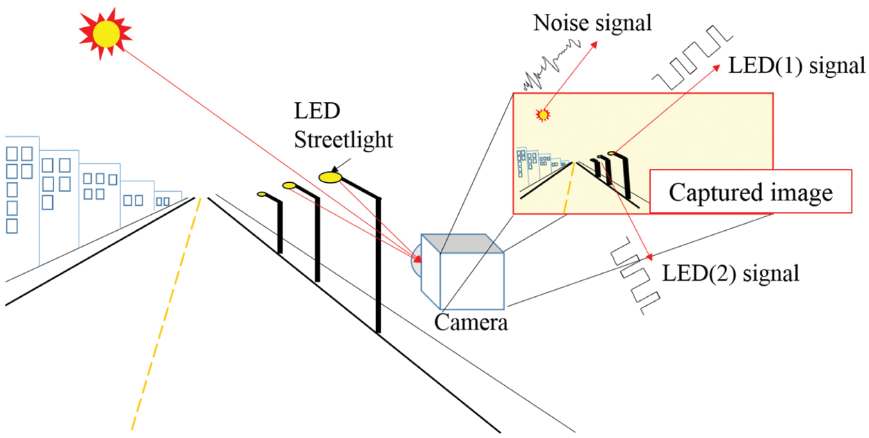
Figure 1: Optical camera communication (OCC)
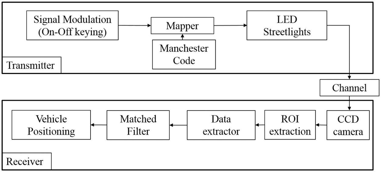
Figure 2: Block diagram of OCC transmitter and receiver
In the envisioned scenario, the streetlights will encode and transmit the information via optical communication to the vehicle, which uses a camera to receive it. In a real practical scenario, as the streetlight positions are fixed relative to the car, the position information could easily be encoded in the streetlights. For instance, we can use several methods (e.g., GPS, differential GPS, RADAR, LiDAR, and ultrasonic waves) to measure the actual coordinates of streetlights [8,9]. Then, this exact location will be included in the public map, which will subsequently be used by the AV. Note that by using several methods, we can correct for the errors and measure the absolute coordinate as accurate as possible. For the transmission of data, among the communication techniques suggested by the IEEE Standards Association [41], the on-off keying (OOK) modulation technique is applied. Fig. 3 shows the OOK modulation based on the “ONs” and “OFFs” of LED. As shown in Fig. 3, LED turn “ON” when the data “1” is transmitted, while it turns “OFF” when the data “0” is transmitted. The
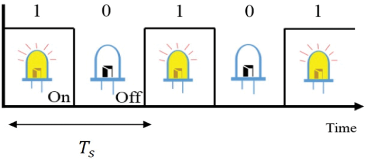
Figure 3: On-off keying (OOK) by using LED
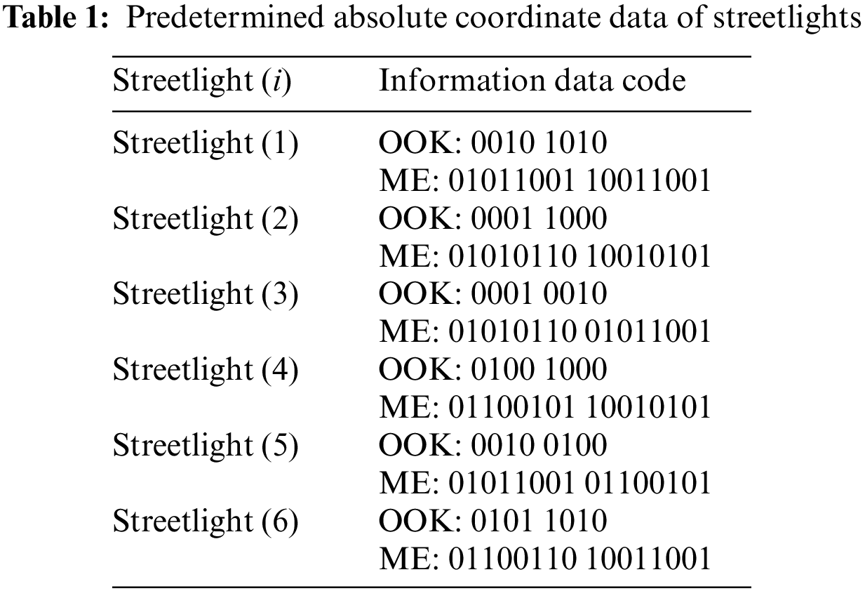
In the proposed scheme, the streetlights transmit the OOK modulated data to a camera on the vehicle, which receives the signal using OCC. Note that the transmission rate of LED streetlights and the frame rate of a camera must be synchronized for communication to occur. In particular, using the OOK modulation and Manchester encoding (ME) [26,30,42], a transmission frame is formed as shown in Fig. 4. This transmission frame is then used to receive the streetlight IDs to get the location information on each streetlight. First, a data frame is formed to transmit and receive information on the absolute coordinates of streetlights. The data frame consists of a total of 12 bits that include 4 bits of “sync data” and 8 bits of “information data”. The sync data is set for synchronization between transmission frames. The sync data is fixed at “1, 1, 1, 1”, while the information data can be set at any values as long as they do not overlap with the sync data. The absolute coordinates of individual streetlights are transmitted and received in the form of predetermined information as shown in Tab. 1, rather than the actual absolute coordinates (with a view to verify the performance of OCC-based V2I communication). In this case, ME is applied and transmitted to prevent the flicker phenomenon of LED streetlights from being recognized by human eyes. The ME is set to reverse signals by changing the data “1” to “1, 0” and the data “0” to “0, 1”. The data rate is lowered two times compared to the OOK, but the LED dimming level is kept constant by equalizing the ratio of data “1” and “0” within the transmission frame structure. This will not affect the principal role of LED for lighting purpose. The transmission frame with ME used in this experiment was set at a total of 24 bits as shown in Fig. 4b.

Figure 4: Data frame structure: (a) Data frame (b) Transmission frame with manchester encoding
In the V2I environment, a vehicle camera can distinguish the information received from LED streetlights located at a long distance. The camera can also analyze a series of images to receive the change of “ONs” and “OFFs” of individual streetlights. For instance, if a video is filmed at 30 frames per second (fps), it is possible to receive 30 LED amplitude changes per second for each streetlight. As shown in receiver block diagram (in Fig. 2), the region of each streetlight displayed on images can be detected, traced, and analyzed to obtain information, and collinearity conditions are used subsequently to estimate the location of a vehicle.
2.2.1 Detection of Streetlight Region
In this paper, an image differential method [29,43], as shown in Fig. 5, is used to detect the region of streetlights in images. Images obtained from a camera have the state of “ON” or “OFF” depending on the transmission data of LED streetlights. In conventional image differential method, a difference image is generated from two consecutive image frames. In first case, if the two consecutive image frames are “ON” and “OFF” frames, the background part with a similar value of brightness is removed, and the region of streetlights with large differences in the value of brightness becomes visible. However, in the case of “ON-ON” or “OFF-OFF” image frames, the region of streetlights is also eliminated due to similar values of brightness. In order to overcome this limitation, in this paper, difference images for three consecutive images are accumulated as shown in Fig. 5. The reason for using three consecutive images is that “ON-OFF” or “OFF-ON” images continue at least one time for every three consecutive images due to the feature of Manchester encoded data.

Figure 5: Image differential method
Fig. 6 shows an example of using the image differential method based on images obtained from an actual experiment. Figs. 6a–6c indicate three consecutive images while Figs. 6d and 6e are the results of difference images. Fig. 6f shows the results of the accumulation of difference images with noise removed and all streetlights displayed. Fig. 6g shows the results of binarization of Fig. 6f, while Fig. 6h displays the results of applying morphology, which is aimed at removing the noise that exists in Fig. 6g. The image differential method is used periodically to adapt to changes in the region of streetlights due to the moving vehicle.

Figure 6: Image differential procedures: (a) nth image (b)
2.2.2 Tracing the Region of Streetlights
In this paper, a block matching technique [40,44,45] is used to trace the region of streetlights. Note that the image differential method has the advantage of detecting the region of streetlights without additional information, but has a limitation of lengthy computation due to the usage of three images. Therefore, the block matching technique is utilized, which increases the cycle of using the image differential method and enables detecting the region of streetlights based on only one image. In the block matching technique, after image binarization, streetlights are copied in the form of block based on the information on the region of streetlights. Then, labeling procedures on the image are performed. This will update information on the region of individual streetlights. In this technique, the size of block is set to be larger than the previous region of streetlights. The reason being correction of the region is needed because the location of the region of streetlights changes in the image of a moving camera.
OCC-based data decoding is performed by distinguishing differences in pixel value of “ONs” and “OFFs” of individual streetlights in the image obtained from a camera. In the proposed scheme, the average value of pixels included in each region of streetlights was calculated and used to clarify the distinction of “ONs” and “OFFs”. Fig. 7 shows region of streetlights used to calculate the average value of pixels. A threshold value is used to distinguish average pixel values depending on “ON” and “OFF”. Data is defined to be “1” if it is larger than the threshold and “0” if it is smaller than the threshold. The brightness of streetlights displayed on a camera changes depending on the movement of a vehicle and the surrounding environment.
Therefore, we update the threshold value with the maximum and minimum values out of the average pixel values of individual streetlights obtained from the previous eight frames. Even in a single image, threshold values are different for each region of streetlights and change depending on the situation.

Figure 7: Image regions for data analysis
2.2.4 Reception of Information Through Matched Filter
We use a matched filter for the information detection, i.e., if the received data matches with the transmitted data frame, the matched-filter detects the relevant information. Moreover, as the transmission frame structure consists of a total of 24 bits, the matched-filter works when at least 24 bits of data are accumulated. In order to ensure that the size of the received data is equal to that of the transmitted frame, the received data is defined to consist of a total of 24 bits, including the data from
Moreover, the received data is obtained as many times as the number of the detected regions j. The Eq. (2) below indicates the procedure for matching the top 8 bits of the received data with the sync data.
Eq. (3) below indicates procedures for matching the remaining 16 bits of the received data with the information data illustrated in Tab. 1.
where i represents the index of streetlights written in Tab. 1. These two procedures do not take place simultaneously. When the received data match with the sync data, it is matched with the information data of individual streetlights. On the other hand, if the received data do not match with the sync data, the data of individual streetlights are received from
In this paper, the image differential method is used to initialize the region of streetlights at a frequency of 60 fps. When the absolute coordinates of at least three or more streetlights are received with this frequency, a vehicle positioning algorithm is performed. If information on the locations of three or more streetlights is received during one period, three streetlights with top priority are selected to update the estimated locations. In the proposed scheme, streetlights in the top region on the image are given higher priority in selection. In other words, higher priority is given if the value of row among the coordinate components of a streetlight is lower.
3 Vehicle Positioning Scheme Based on Absolute Coordinates of LED Streetlights
For determining the VP using collinearity conditions [13], it is necessary to obtain the coordinates of individual streetlights displayed on an image sensor, which are information on 3D space as shown in Fig. 8. As shown in Fig. 9, the size of pixels on an image sensor is defined by using the ratio of a camera image to an image sensor as shown below [46,47]:

Figure 8: Vehicle positioning system based on the absolute coordinates of three streetlights

Figure 9: Ratio of a camera image to an image sensor
where

Figure 10: Placement of lens and image sensor
3.2 Vectors Based on Image Sensor Coordinates and Absolute Coordinates
Fig. 11 illustrates the definitions of vectors based on image sensor coordinates and absolute coordinates. Eq. (5) represents a vector based on the focal length of a camera and the coordinates of an image sensor.
The Eq. (6) below represents a vector based on the absolute coordinates of a camera and streetlights.
In this paper, the unit vectors X, Y on the absolute coordinates are set to be equal to the unit vectors u, v on the image sensor coordinates, and Z is set to be equal to the focal length f.

Figure 11: Absolute coordinates and image sensor coordinates
A vector based on the absolute coordinates of 3D space includes the absolute coordinates of a camera. The absolute coordinates of a camera are estimated based on the fact that the coordinates of three streetlights

Figure 12: Characteristics of vectors based on collinearity conditions
In the proposed scheme, inner product is formed between the unit vectors of the image sensor-based vectors to obtain the angles of a, b, and c, as shown below:
Then, we obtain the absolute coordinates of a camera as shown below:
Here, absolute coordinates are included in absolute coordinate-based vectors where the angles of
In this paper, two experiments were conducted to verify the proposed OCC-based VP scheme using the absolute coordinates of streetlights. First, comparison was made between the location of a camera, which was actually measured in the stationary state, and the estimated location of a camera. Next, comparison was made between the path of a vehicle in the moving state and the estimated path of a vehicle. Fig. 13 shows the experimental environment where 3D space was defined by using X, Y, and Z axes. The point where streetlight (2) meets the ground is the center point of the absolute coordinate, and the remaining streetlights are relatively placed as indicated by the coordinates in the figure. In addition, in the proposed scheme, the LED flicker rate and the camera frame rate should match for communication to occur.

Figure 13: Experimental environment with streeting (1) to streetlight (6)
An experiment in the stationary state is conducted by comparing the actually measured and estimated locations of a camera in order to verify the reliability of the suggested scheme. Fig. 14 shows the location of a camera actually measured in the stationary state experiment. Regarding experimental procedures, the experiment was conducted a total of 24 times as a vehicle moved

Figure 14: Experimental environment and scenario in stationary state
Figs. 15a–15c illustrate the actual and estimated locations of each axis, whereas Fig. 15d shows errors in estimation for each axis. In Fig. 15d and Tab. 2, the errors of all axes were found to be less than 1 m. In addition, Fig. 15d shows that errors became large starting from the point of around 28 m. This point is where the number of streetlights displayed on a camera image changed from six to four. In other words, the greater number of streetlights means the higher accuracy of vehicle positioning. Note that the position estimation error is large in

Figure 15: Results and errors of vehicle positioning: (a)
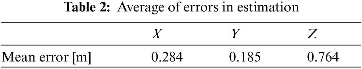
Fig. 16 shows the experimental environment in the moving state where six streetlights and an actual vehicle were used. Moreover, as shown in the figure, the transmission rate of LED streetlights and the frame rate of a camera were synchronized at 250 Hz and 250 fps respectively. Note that even though the LED flicker rate is 250 Hz, following OOK modulation shown in Fig. 3, the maximum frequency present in the transmitted signal is 125 Hz only. Therefore, sampling at a camera with 250 fps does not violate the Nyquist criteria. Experiment procedures were performed at each speed of a vehicle (5 and 20 km/h).

Figure 16: Experimental environment (moving state)
In addition, for the vehicle speed of 20 km/h, the experiment was conducted separately in daytime and nighttime. In the nighttime, the experiment was conducted with the headlights of a vehicle “ON” and “OFF”.
Figs. 17a–17d indicate the estimated location of a vehicle in the environment where the vehicle speed was 5 km/h, 20 km/h-daytime, 20 km/h-nighttime (headlights-ON), and 20 km/h-nighttime (headlights-OFF), respectively. Fig. 17a is the environment with the lower speed of a vehicle than the speeds of a vehicle in Figs. 17b–17d. As a result, when a vehicle travelled in the same distance, more positioning data could be obtained to produce positioning results in higher accuracy. Based on this fact, it was found that as the reception rate of a camera increases, which means that more images per second were obtained from a camera, it was possible to get more positioning data, which resulted in the higher accuracy of mobile vehicle positioning. Moreover, the experiment results did not show much difference between the daytime and nighttime environment and between when the headlights were “ON” and “OFF” before data were received. Note that it is very difficult to record the exact real position of a continuously-moving car, and hence, it is not possible to compute the error data in moving state. Therefore, we have already investigated the accuracy of our algorithm in the stationary state. The objective of moving state experiments is primarily to give experimental validation to our scheme for real life cases of interest.
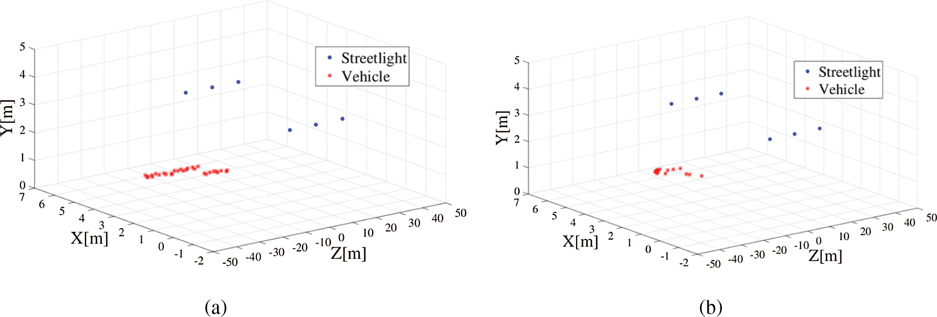

Figure 17: Experimental results in moving state: (a) 5 km/h (b) 20 km/h-daytime (c) 20 km/h-nighttime (headlights- ON) (d) 20 km/h-nighttime (headlights-OFF)
This paper proposed a scheme to supplement conventional VP technology through OCC-based VP in the V2I environment, particularly for the autonomous vehicles. Detecting and tracing the region of streetlights, data decoding, and matched-filter technique were utilized to ensure the OCC between LED streetlights and a car camera. The location of a vehicle was estimated based on the assumption of the absolute coordinates of at least three streetlights in 3D space and the collinearity conditions of the coordinates of three streetlights in an image sensor. In the experiment, the absolute coordinates of streetlights were received to be used for VP, and the experiment results verified the possibility of OCC-based V2I communication. In the stationary state experiment, all errors in vehicle positioning on X, Y, and Z axes were less than 1 m, and the performance was higher when more streetlights were available for estimation.
Lastly, in the moving state experiment, the results showed that the location of a vehicle was similar to the actual path of a vehicle regardless of daytime or nighttime and the use of headlights. When the speed of a vehicle varied in the experiment, more data for vehicle positioning could be obtained at a lower speed, which demonstrated the higher accuracy of vehicle positioning. The experimental results verified that the OCC-based VP scheme using the absolute coordinates of streetlights enables estimating the location of a vehicle in an urban area or a tunnel. We acknowledge that there are still several challenges regarding the implementation of our proposed scheme in the real case of interest for vehicles moving at standard velocities (speed >= 50 km/h), note that this is just a first step of development of a more complex system to be optimized in future developments.
Funding Statement: This work was supported by the National Research Foundation of Korea (NRF) grant funded by the Korean government (NRF-2018R1A2B6002204).
Conflicts of Interest: The authors declare that they have no conflicts of interest to report regarding the present study.
1. M. N. Eisler, “A Tesla in every garage?,” IEEE Spectrum, vol. 53, no. 2, pp. 34–55, 2016. [Google Scholar]
2. L. Gomes, “When will Google's self-driving car really be ready? It depends on where you live and what you mean by “ready” [News],” IEEE Spectrum, vol. 53, no. 5, pp. 13–14, 2016. [Google Scholar]
3. D. J. Fagnant and K. Kockelman, “Preparing a nation for autonomous vehicles: Opportunities, barriers and policy recommendations,” Transportation Research Part a: Policy and Practice, vol. 77, pp. 167–181, 2015. [Google Scholar]
4. C. Fernandes, K. Y. Ng and B. H. Khoo, “Development of a convenient wireless control of an autonomous vehicle using apple iOS SDK,” in Proc. IEEE Region 10 Conf. (TENCON), Bali, Indonesia, pp. 1025–1029, 2011. [Google Scholar]
5. A. Islam, U. Iqbal, J. Langlois and A. Noureldin, “Implementation methodology of embedded land vehicle positioning using an integrated GPS and multi sensor system,” Integrated Computer-Aided Engineering, vol. 17, no. 1, pp. 69–83, 2010. [Google Scholar]
6. Y. Cui and S. S. Ge, “Autonomous vehicle positioning with GPS in urban canyon environments,” IEEE Transactions on Robotics and Automation, vol. 19, no. 1, pp. 15–25, 2003. [Google Scholar]
7. S. Savasta, M. Pini and G. Marfia, “Performance assessment of a commercial GPS receiver for networking applications,” in Proc. 5th IEEE Consumer Communications and Networking Conf. (CCNC), Las Vegas, NV, USA, pp. 613–617, 2008. [Google Scholar]
8. C. Waldschmidt and H. Meinel, “Future trends and directions in radar concerning the application for autonomous driving,” in Proc. 11th European Radar Conf. (EURAD), Rome, Italy, pp. 416–419, 2014. [Google Scholar]
9. J. K. Kim, J. W. Kim, J. H. Kim, T. H. Jung, Y. J. Park et al., “Experimental studies of autonomous driving of a vehicle on the road using LiDAR and DGPS,” in Proc. 15th Int. Conf. on Control, Automation and Systems (ICCAS), Busan, Korea (Southpp. 1366–1369, 2015. [Google Scholar]
10. S. -W. Ko, H. Chae, K. Han, S. Lee, D. -W. Seo et al., “V2X-based vehicular positioning: Opportunities, challenges, and future directions,” IEEE Wireless Communications, vol. 28, no. 2, pp. 144–151, 2021. [Google Scholar]
11. M. Hossan, M. Z. Chowdhury, M. Hasan, M. Shahjalal, T. Nguyen et al., “A new vehicle localization scheme based on combined optical camera communication and photogrammetry,” Mobile Information Systems, vol. 2018, 2018. [Google Scholar]
12. J. He and B. Zhou, “Vehicle positioning scheme based on visible light communication using a CMOS camera,” Optics Express, vol. 29, no. 17, pp. 27278–27290, 2021. [Google Scholar]
13. B. W. Kim and S. -Y. Jung, “Vehicle positioning scheme using V2V and V2I visible light communications,” in Proc. IEEE 83rd Vehicular Technology Conf. (VTC-Spring), Nanjing, China, pp. 1–5, 2016. [Google Scholar]
14. N. Vivek, S. Srikanth, P. Saurabh, T. Vamsi and K. Raju, “On field performance analysis of IEEE 802.11 p and WAVE protocol stack for V2V & V2I communication,” in Proc. Int. Conf. on Information Communication and Embedded Systems (ICICES2014), Chennai, India, pp. 1–6, 2014. [Google Scholar]
15. A. Hussein, F. Garcia, J. M. Armingol and C. Olaverri-Monreal, “P2V and V2P communication for pedestrian warning on the basis of autonomous vehicles,” in Proc. IEEE 19th Int. Conf. on Intelligent Transportation Systems (ITSC), Rio de Janeiro, Brazil, pp. 2034–2039, 2016. [Google Scholar]
16. K. S. Sheela and S. Padmadevi, “Survey on street lighting system based on vehicle movements,” International Journal of Innovative Research in Science, Engineering and Technology, vol. 3, no. 2, pp. 9220–9225, 2014. [Google Scholar]
17. A. Gil-de Castro, A. Moreno-Munoz, A. Larsson, J. G. de la Rosa and M. Bollen, “LED street lighting: A power quality comparison among street light technologies,” Lighting Research & Technology, vol. 45, no. 6, pp. 710–728, 2013. [Google Scholar]
18. S. Arnon, J. Barry, G. Karagiannidis, R. Schober and M. Uysal, in Advanced Optical Wireless Communication Systems, Cambridge, UK: Cambridge university press, 2012. [Google Scholar]
19. M. Z. Chowdhury, M. T. Hossan, A. Islam and Y. M. Jang, “A comparative survey of optical wireless technologies: Architectures and applications,” IEEE Access, vol. 6, pp. 9819–9840, 2018. [Google Scholar]
20. H. B. Eldeeb, S. M. Sait and M. Uysal, “Visible light communication for connected vehicles: How to achieve the omnidirectional coverage?,” IEEE Access, vol. 9, pp. 103885–103905, 2021. [Google Scholar]
21. P. H. Pathak, X. Feng, P. Hu and P. Mohapatra, “Visible light communication, networking, and sensing: A survey, potential and challenges,” IEEE Communications Surveys & Tutorials, vol. 17, no. 4, pp. 2047–2077, 2015. [Google Scholar]
22. S. Vappangi and V. Mani, “Concurrent illumination and communication: A survey on visible light communication,” Physical Communication, vol. 33, pp. 90–114, 2019. [Google Scholar]
23. N. Saha, M. S. Ifthekhar, N. T. Le and Y. M. Jang, “Survey on optical camera communications: Challenges and opportunities,” IET Optoelectronics, vol. 9, no. 5, pp. 172–183, 2015. [Google Scholar]
24. T. Nguyen, A. Islam, T. Hossan and Y. M. Jang, “Current status and performance analysis of optical camera communication technologies for 5G networks,” IEEE Access, vol. 5, pp. 4574–4594, 2017. [Google Scholar]
25. S. Teli, W. A. Cahyadi and Y. H. Chung, “Optical camera communication: Motion over camera,” IEEE Communications Magazine, vol. 55, no. 8, pp. 156–162, 2017. [Google Scholar]
26. N. T. Le, M. A. Hossain and Y. M. Jang, “A survey of design and implementation for optical camera communication,” Signal Processing: Image Communication, vol. 53, pp. 95–109, 2017. [Google Scholar]
27. T. Nguyen, C. H. Hong, N. T. Le and Y. M. Jang, “High-speed asynchronous Optical camera communication using LED and rolling shutter camera,” in Proc. Seventh Int. Conf. on Ubiquitous and Future Networks (ICUFN), Sapporo, Japan, pp. 214–219, 2015. [Google Scholar]
28. S. H. Lee, S. -Y. Jung and J. K. Kwon, “Modulation and coding for dimmable visible light communication,” IEEE Communications Magazine, vol. 53, no. 2, pp. 136–143, 2015. [Google Scholar]
29. B. W. Kim and S. -Y. Jung, “Novel flicker-free optical camera communications based on compressed sensing,” IEEE Communications Letters, vol. 20, no. 6, pp. 1104–1107, 2016. [Google Scholar]
30. N. Saeed, S. Guo, K. -H. Park, T. Y. Al-Naffouri, and M. -S. Alouini, “Optical camera communications: Survey, use cases, challenges, and future trends,” Physical Communication, vol. 37, pp. 100900, 2019. [Google Scholar]
31. J. -H. Yoo, J. -S. Jang, J. Kwon, H. -C. Kim, D. -W. Song et al., “Demonstration of vehicular visible light communication based on LED headlamp,” International Journal of Automotive Technology, vol. 17, no. 2, pp. 347–352, 2016. [Google Scholar]
32. S. Nishimoto, T. Nagura, T. Yamazato, T. Yendo, T. Fujii et al., “Overlay coding for road-to-vehicle visible light communication using LED array and high-speed camera,” in Proc. 14th Int. IEEE Conf. on Intelligent Transportation Systems (ITSC), Washington, DC, USA, pp. 1704–1709, 2011. [Google Scholar]
33. Y. Feng, Z. Zhu and J. Xiao, “Self-localization of a heterogeneous multirobot team in constrained 3D space,” in Proc. IEEE/RSJ Int. Conf. on Intelligent Robots and Systems (IROS), San Diego, California, USA, pp. 1343–1350, 2007. [Google Scholar]
34. T. -H. Do and M. Yoo, “An in-depth survey of visible light communication-based positioning systems,” Sensors, vol. 16, no. 5, pp. 678, 2016. [Google Scholar]
35. M. Afzalan and F. Jazizadeh, “Indoor positioning based on visible light communication: A performance-based survey of real-world prototypes,” ACM Computing Surveys (CSUR), vol. 52, no. 2, pp. 1–36, 2019. [Google Scholar]
36. G. A. Mapunda, R. Ramogomana, L. Marata, B. Basutli, A. S. Khan et al., “Indoor visible light communication: A tutorial and survey,” Wireless Communications and Mobile Computing, vol. 2020, 2020. [Google Scholar]
37. T. Yamazato, I. Takai, H. Okada, T. Fujii, T. Yendo et al., “Image-sensor-based visible light communication for automotive applications,” IEEE Communications Magazine, vol. 52, no. 7, pp. 88–97, 2014. [Google Scholar]
38. Z. Zheng, L. Liu and W. Hu, “Accuracy of ranging based on DMT visible light communication for indoor positioning,” IEEE Photonics Technology Letters, vol. 29, no. 8, pp. 679–682, 2017. [Google Scholar]
39. Z. Ghassemlooy, P. Luo and S. Zvanovec, “Optical Camera Communications,” in Optical Wireless Communications, Switzerland: Springer, pp. 547–568, 2016. [Online]. Available: https://link.springer.com/chapter/10.1007/978-3-319-30201-0_25#citeas. [Google Scholar]
40. S. Arai, Y. Shiraki, T. Yamazato, H. Okada, T. Fujii et al., “Multiple LED arrays acquisition for image-sensor-based I2V-VLC using block matching,” in Proc. IEEE 11th Consumer Communications and Networking Conf. (CCNC), Las Vegas, NV, USA, pp. 605–610, 2014. [Google Scholar]
41. “IEEE standard for local and metropolitan area networks–Part 15.7: Shortrange wireless optical communication using visible light,” IEEE Std 802.15.7-2011, pp. 1–309, 2011. [Google Scholar]
42. C. Danakis, M. Afgani, G. Povey, I. Underwood and H. Haas, “Using a CMOS camera sensor for visible light communication,” in Proc. IEEE Globecom Workshops (Globecom), Anaheim, CA, USA, pp. 1244–1248, 2012. [Google Scholar]
43. D. N. Choi, S. Y. Jin, J. Lee and B. W. Kim, “Deep learning technique for improving data reception in optical camera communication-based V2I,” in Proc. 28th Int. Conf. on Computer Communication and Networks (ICCCN), Valencia, Spain, pp. 1–2, 2019. [Google Scholar]
44. A. H. Azhar, T. -A. Tran and D. O'Brien, “A Gigabit/s indoor wireless transmission using MIMO-OFDM visible-light communications,” IEEE Photonics Technology Letters, vol. 25, no. 2, pp. 171–174, 2012. [Google Scholar]
45. M. T. Niaz, F. Imdad, W. Ejaz and H. S. Kim, “Compressed sensing-based channel estimation for ACO-OFDM visible light communications in 5G systems,” EURASIP Journal on Wireless Communications and Networking, vol. 2016, no. 1, pp. 1–14, 2016. [Google Scholar]
46. R. I. Hartley and A. Zisserman, Multiple View Geometry in Computer Vision, 2nd ed., Cambridge, UK: Cambridge University Press, 2004. [Google Scholar]
47. W. Förstner and B. P. Wrobel, Photogrammetric Computer Vision, Switzerland: Springer, 2016. [Google Scholar]
 | This work is licensed under a Creative Commons Attribution 4.0 International License, which permits unrestricted use, distribution, and reproduction in any medium, provided the original work is properly cited. |