DOI:10.32604/cmc.2022.024390
| Computers, Materials & Continua DOI:10.32604/cmc.2022.024390 | |
| Article |
Feedline Separation for Independent Control of Simultaneously Different Tx/Rx Radiation Patterns
School of Telecommunication Engineering, Suranaree University of Technology, Nakhon Ratchasima, 30000, Thailand
*Corresponding Author: Monthippa Uthansakul. Email: mtp@sut.ac.th
Received: 15 October 2021; Accepted: 25 January 2022
Abstract: The shortcoming of Wi-Fi networks is that one user can access the router at a time. This drawback limits the system throughput and delay. This paper proposes a concept of Simultaneously Different Tx/Rx (SDTR) radiation patterns with only one antenna set at the router. Furthermore, these two patterns have to be simultaneously operated at the same time so that the system delay can be eased. An omni-directional pattern is employed at router for receiving mode so that the router can sense carrier signal from all directions. At the same time, the router launches a directional beam pointed to another user. A proposed circuit allows these two modes to be able to operate the same time. To evaluate the SDTR concept, a prototype is constructed for testing in real circumstance comparing to computer simulation. As a result, the SDTR concept can improve the system throughput while decreasing the system delay comparing to conventional system.
Keywords: Wireless networks; wi-fi; throughput; delay; radiation pattern
As we all know, antennas are an essential element used in transmitting and receiving signals for wireless communications. Two well-known types of antennas are omni-directional and directional antenna. The omni-directional antenna is suitable for equally radiating power in all directions. For this case, a Whip antenna has been introduced for the use in VHF and UHF bands with the gain of 6.8 dB [1]. The authors of [2] have investigated the use of monopole antenna for radio-frequency heating and microwave communications at 1.8, 2.4, and 2.56-GHz bands. In addition, the works presented in [3] have revealed the single circular patch antenna for Global Positioning System (GPS) application at 2.28–2.40 and 3.30–3.60 GHz. However, this kind of antenna faces the problems of low-gain radiation, low capacity and also high interference signal. One way to deal with the mentioned problem is to limit the radiation in one specific area, so called directional antenna. The higher radiation gain can be specifically pointed to one direction while having low gain in other undesired directions to avoid the interference signal. So far, directional antenna can be classified into two major categories: traditional directive antenna and smart antenna. The traditional directive antenna is a single antenna element in which its construction allows the radiation to be focused in one specific direction. Some examples of this kind of antenna are shown as follows. A horn antenna has been investigated for the use in radar communication [4]. Also, a specific reflector antenna has been designed for full-duplex application as presented in [5]. For having more degrees of freedom, a smart antenna has been developed employing an array antenna cooperating with some signal processing units. The smartness of this system is reflected by the allowance of controllable beam formation. There are three categories of smart antenna: switched beam, steerable beam and adaptive antennas. The switched beam antenna radiates the maximum power in a pre-defined direction while providing a low gain in other directions. However, when the users move away from the main beam, they will receive a weak signal. For this case, other pre-defined beams can be applied to the system in order to provide a high radiation gain to the users. One good example of this antenna has been shown in [6] which is a switched beam antenna for 5G wireless communication systems supporting a large number of users at 60-GHz band. In addition, the steerable single beam antenna has a similar performance of switched-beam antenna but it has higher advantage in an interference cancellation as it can steer nulls to interference directions. One interesting example has been introduced in [7] which is a steerable beam antenna using dielectric lens to control the directions of nulls and beams for wireless network communications. The most powerful smart antenna is the adaptive antenna as it can automatically steer its main beam and nulls to directions of desired and undesired directions, respectively. This can be accomplished by many effective algorithms proposed in literatures [8].
As far as we know, the antenna has a reciprocal property which allows the similarity of receiving and transmitting radiation patterns. However, the works presented in [9,10] have revealed that a difference between transmitting and receiving radiation patterns provides an improved performance for wireless communications. One application employs different transmitting and receiving radiation patterns is Wireless Networks With Directional Antennas (DAWNs). The mentioned difference is to increase the accuracy of users’ location positioning and also decrease the interference from adjacent users. However, in order to achieve the benefits of having different radiation patterns in transmitting and receiving modes, we need to have at least two sets of antennas e.g., one array antennas for transmitting mode and another one for receiving mode. This concept might result in high complexity and cost.
From the above drawbacks, we are interested in the utilization of different radiation patterns in transmitting and receiving modes. We use the feedline separation for control the Simultaneously Different Tx/Rx (SDTR) radiation patterns. The possible concept can be categorized into four radiation schemes (types C, D, E and F) as shown in Fig. 1. For type C, one set of array antennas is employed to generate two different radiation patterns for receiving and transmitting modes. This type is suitable for Wi-Fi system as the base station is able to communicate to a desired user with maximum gain when the directional pattern is employed for transmitting mode. At the same time, an omni-directional pattern is active when the base station works in receiving mode. This helps the base station is able to sense the users in all directions. According to this, the user accessibility and capacity are more efficient comparing to the traditional system which employs the same pattern for both transmitting and receiving modes. For type D, the radiation patterns in receiving and transmitting modes are directional and omni-directional, respectively. This type is suitable for broadcast communications when the center station needs to send the same information with high gain to all directions. For type E, two directional patterns are employed for both transmitting and receiving modes but they are pointed in two different directions. This type is suitable to be installed in the signal repeater. The main beams for this case do not need to be switched as the directions are fixed. However, in some applications, the base station needs to transmit signal to more than one direction so type F is considered. However, the concept of using different radiation patterns at the base station needs to use the array antenna more than one set. This concept introduces a high cost for investment. Another important issue is a suitable protocol for wireless networks to support the user accessibility in space domain. To achieve the utilization in space domain for wireless networks, a Media Access Control (MAC) protocol needs to be modified [11–14]. Still, the user accessibility is not fully efficient as one beam pattern can be occupied by a single user at a time while the others have to wait.
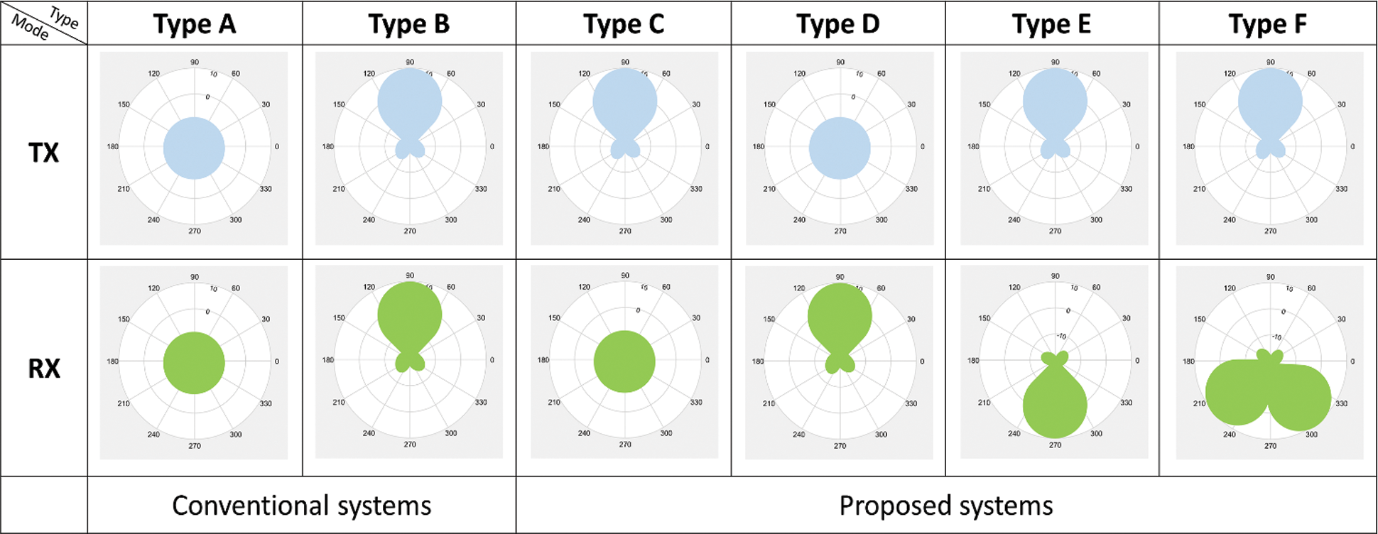
Figure 1: Type of SDTR radiation patterns
From the impairments mentioned earlier, the research work in this paper focuses on a further investigation on the SDTR type C which is the most suitable one for wireless networks as the nodes’ positions are fixed. This concept reduces the users’ waiting time to access the router and decreases the number of hidden nodes. Most importantly, the SDTR antenna is able to serve two different patterns in transmitting and receiving modes using only one antenna set. According to this, the router is able to perform signal transmission and reception at the same time and the same frequency. Furthermore, the SDTR systems do not need a new complex protocol to support the user accessibility in space domain. Therefore, the SDTR systems can be promptly applied to a current wireless network. However, the challenge for this SDTR concept is its feasibility. One important circuit that allows the transmitting and receiving signal to be sent and received from the system at the same time is shown in Fig. 2. The input signal flows through the solid line while the output signal simultaneously flows through the dash line. The system performance in terms of isolation depends on the efficiency of isolators [15]. The phase shifters appeared in the figure is used to adjust the signal phase for two reasons as follows. For the output line, the pre-defined phase shifter allows the signal to be shifted in phase. When all the phase-shifted signals from every element of the array are combined, the downlink beam formation in a given direction can be performed. For the input line, zero-phase shifting is needed when the omni-directional pattern is required for the receiving mode. Another reason of using phase shifters in both lines is to balance the power level between input and output signals. So, this feedline separation in Fig. 2 can independently control the Tx/Rx radiation patterns.

Figure 2: SDTR circuit
From the past, a conventional beamforming system has been proposed as shown in Fig. 3. The phase shifters are employed to deal with the beam formation for both downlink (dash line) and uplink (solid line). Lots of research have been proposed to develop many parts in the system such as beamforming algorithms and antennas. The works presented in [16,17] have been proposed for a design of multiplexers having a 79% higher performance with low power consumption. So far, the downlink and uplink can be operated at different time and frequency to avoid the signal distortion. This results in the limitation of throughput and capacity of the system as multiple users cannot access the base station at the same time. Moreover, the frequency resource is not sufficiently employed.
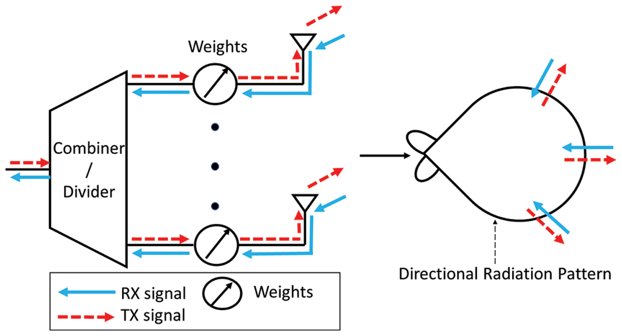
Figure 3: Conventional beamforming systems
From the impairments mentioned above, Fig. 4 shows a new beamforming concept for this paper in which the SDTR circuit shown in Fig. 2 is equipped at individual antenna elements. This SDTR concept allows the difference in radiation patterns for transmitting and receiving modes. Moreover, with the help of SDTR circuit, two different patterns can be operated at the same time and frequency. The shapes of radiation patterns for both modes can be controlled by adjusting the phase shifters, for both uplink (solid line) and downlink (dash line). Furthermore, this SDTR concept does not need any new MAC protocol because only physical layer is modified. This paper is an alternative approach to enhance throughput in Wi-Fi networks. The gain is less complex than resolving multiple access when using different formats.

Figure 4: SDTR beamforming systems
The remainder of this paper is consequently organized as follows. After motivation and contribution are shown in Section 1, Section 2 related work, Section 3 introduces the SDTR system model. Afterwards, the performance of SDTR system is validated through the computer simulation and experiments in Section 4. Finally, the paper is concluded in Section 5.
In the past few years The Wi-Fi communication business has grown exponentially. To support the exponential growth of users in the years to come, researchers need to develop even more Wi-Fi networks. So far in literature, the researchers have focused on two areas: antenna design and multiple access techniques. In antenna design, the main benefits are antenna gain, frequency, size, etc. The dipole array antenna in [18] provides an omnidirectional radiation pattern which is general for Wi-Fi network. The study in [19] presents a low-profile wideband antenna array which the size of antenna is small. So, it is suitable for working on Wi-Fi network. The work in [20] deploys the dual MIMO antenna with a minimal design. There is also space for other devices. This paper is aimed at radiation pattern targets. A typical antenna has two radiation patterns. The omnidirectional format is the preferred format for Wi-Fi networks. The shape of the dipole antenna radiates energy in all directions. So the advantage is that users around will be able to radiate energy in all directions The transmitter can receive signals in all directions. The second is the directional radiation pattern. This format differs from the omnidirectional version in relation to the antenna gain. Because the power is sent from the transmitter in one direction. The two common radiation patterns have different working areas. So these are the factors we consider due to the merits of each format used.
Today the network is accessed many times. Accessing multiple items of interest adds users to the network. Frequency Divided Multiple Access (FDMA) uses multiple frequencies to stream to users. and time-division multiple access (TDMA) uses different time intervals [21]. Additionally, FDMA and TDMA were studied to create a high-traffic TDMA algorithm when a user connects to a transmitter simultaneously. In FDMA, interference occurs and transmission stops because all users in the network share a frequency channel and use the same frequency. Code segment access (CDMA) uses the same carrier frequency. But there are different codes in [22]. The weakness of CDMA is that the number of users in the network deteriorates the overall service quality. A popular multiple access format is orthogonal frequency segment access (OFDMA) [23], improving network capacity and high data rates. However, OFDMA is complex for devices and that sensitivity is for frequency compensation [24]. Another is non-orthogonal multiple access (NOMA) [25]. There is highly efficient and has better security for the user. The work in [26] proposed the novel NOMA with antenna number modulation (ANM) bits for the symbol to transmission. This still does not have a standard drive for this novel NOMA. So, it will be hard to implement to device and popular. The NOMA has a weakness in complexity because it uses ineffective receiver-side successive interference cancellation (SIC) [27]. Moreover, NOMA uses far and near users to calculate the transmission. So, it is not fair for other users. Although, the mentioned above are helpful to support networks both directly and indirectly. However, the alternative approach to support the number of users is still necessary.
This paper is an alternative way to help Wi-Fi networks. This article also focuses on radiation patterns that are part of the physical layer. This layer can be applied to a variety of accessibility techniques. The design is a passive device. So it doesn't fix the new multiple access technique for the complex.
Nowadays, the demand of Wi-Fi communications has been dramatically increased and also lots of updated gadgets have been lately launched to serve people's daily lives. Therefore, the development of Wi-Fi systems is currently one of the most research topics. In fact, antenna radiation pattern is also significant for the performance of Wi-Fi communications. In some cases, lots of hidden terminals occurs when the radiation pattern is not suitable [28–30]. Fig. 5a shows a pair of router nodes which radiate equal power in all direction, having omni-direction patterns. Note that the system employs TDMA (Time Division Multiple Access) with the same operating frequency. The drawbacks of this network configuration are that the radiated power is relatively low, and the system delay occurs by the following reason. While the Router 2 is connecting with User 2, ORTS (Omi-directional Request to Send) sent from Router 1 is failed. At this point, Router 1 keeps sending ORTS to Router 2 for a given period. As a result, User 1 cannot access Router 1 which introduces a delay to the system. However, the system delay still occurs even when routers alternatively employ directional patterns instead as shown in Fig. 5b. For this case, the DRTS (Directional Request to Send) sent from User 3, which stays outside the pattern of Router 1, is also failed. The system delay for this case is worse comparing to the case shown in Fig. 5a. Also, Fig. 5c shows the case of signal collision occurring from the moderate level of side lobes at routers. The signal from the communication between Router 1 and User 1 interferes the received signal at Users. Therefore, the data collision fails the communication between Router 2 and User 2. From the above impairments, this paper proposes the concept of having two different patterns between transmitting and receiving modes as shown in Fig. 5d. As seen in the figure, Router 1 can continually communicate with User 1 using directional pattern while it is able to simultaneously sense the request signal in all directions using omni-directional receiving capability (omni-directional pattern). Moreover, the array antennas are employed at router nodes so that low sidelobe levels can be controlled to avoid the signal collision at User 2. According to the SDTR systems, more users are able to access the router, hence not only the delay decreases and also the throughput of the system increases.

Figure 5: The problem scenarios in Wi-Fi networks: (a) hidden terminal problem with omni-directional pattern; (b) hidden terminal problem with directional pattern; (c) signal collision with directional pattern; (d) SDTR systems
In this paper,
where
where
where
where
where
where
where
3.2 Interference and Active Node Pair
This paper focuses on the scenario of active node pair in case of downlink communication. The area of communication is assumed as a circle as shown in Fig. 6. Also, the interference signal comes from three different areas. The first one is the area defined with the radius between

Figure 6: Network scenario for simulation
Type A is the scenario in which the radiation patterns of transmitter and receiver are omni-directional. The interference signal power coming from many directions is defined in Eq. (9).
where
where
where r is the range of the network. Referring to [31], the number of success users is defined with the margin of
where
For the directional pattern outside the 3-dB beamwidth, the
The SINR which is affected by interference and noise can be defined in Eq. (16).
where
where
The communication scenario specifies the access signal from the device as a user. So, authors define
where
For Type B, both transmitter and receiver employ directional antenna patterns. In this case, the interference signal comes from the area outside 3-dB beamwidth. The power of interference signal for this case is defined as follows.
Also, the number of active node pair for this case can be found using (23).
where
For Type C, a directional antenna pattern is employed for transmitting mode while omni-directional antenna pattern is employed for receiving mode. Note that bot patterns are simultaneously operated at the same time. Then, the number of successful users for this case is defined in Eq. (26).
where
3.3 Radiation Pattern and MAC Protocol
This section presents the protocol mechanism of IEEE 802.11 DCF involving to Carrier-Sense Multiple Access (CSMA) [32–36]. From Fig. 7, the conventional system is defined as the router and user employ omni-directional antenna patterns. The communication between a user and router can be seen step-by-step as shown in Fig. 7a. Note that, for this case, two users cannot access the router at the same time. On the other hand, the SDTR systems shown in Fig. 7b are defined as using different patterns between transmitting and receiving modes, directional and omni-directional patterns respectively. These modes are simultaneously operated at the same time, hence the system throughput increases. However, Fig. 7c represents the case when data collision from two users occurs. For this case, both users simultaneously retransmit the signal to router without further delay. This is considered as an advantage point over the conventional systems (Fig. 7a).

Figure 7: SDTR mechanism at router in: (a) conventional system; (b) SDTR system at the general status; (c) SDTR system with the collision situation
So far, Markov chain model has been one popular model to evaluate the networks [32]. In this model, lots of parameters have to be given such as the condition of back-off and the number of active node pair. Also, the work presented in [31] has discussed the performance comparison among directional, switched-beam and adaptive antennas. However, the effect of radiation pattern has not been taken into account. Therefore, this paper considers the effects of active node pair, radiation pattern and MAC protocol employing Markov chain as shown in Fig. 8. In this figure, the counter starts counting from 0 to

Figure 8: Markov chain model
For stationary distribution, the Markov chain has a condition which is
Then, it can be rewritten as:
For the re-transmitting status, it can be expressed as:
When
Therefore, the probability of time slot can be expressed as follows.
When n represents the number of users with the condition of
The system throughput can be given as shown in Eq. (38).
When
Also, the delay of the system can be expressed as:
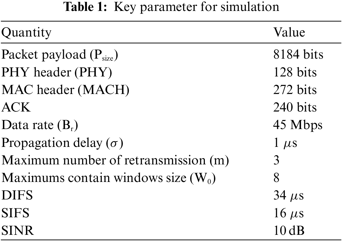
This section expresses the calculating method to evaluate the system performance which are system throughput and delay. Furthermore, the SDTR concept adopts the covering area of antenna to enhance network performance. In next section, we confirm the SDTR concept with the computer simulation and measurement. The simulation parameters can be found in Tab. 1.
This section shows detail of complete circuits for the SDTR systems. Also, the throughput and delay are the parameters to evaluate the performance of SDTR system comparing to the conventional one.
The SDTR concept of this research work is to utilize two different radiation patterns for transmitting and receiving modes at the router. The photograph of measurement in anechoic chamber is shown in Fig. 9. The most challenging point is that these two different patterns are simultaneously operated at the same time and frequency. The 2

Figure 9: Radiation pattern measurement

Figure 10: The radiation patterns of antenna for transmitting and receiving modes: (a) simulated; (b) measured
A prototype of SDTR system shown in Fig. 2 was constructed as shown in Fig. 11. The 2

Figure 11: Photograph of SDTR circuit
In this paper, some scenarios are assumed in computer simulation to evaluate the performance of SDTR systems (Type C) comparing to Types A and B shown in Fig. 1. Tab. 2 shows the number of active node pair when they can simultaneously operate at the same time. As we can see, only one user can access the router (successful node pair) at a given time duration. This is because the radiation pattern of router is omni-directional for both transmitting and receiving modes. So, the router allows the communication with one user at a time and the others are considered to be hidden nodes. In addition, Type B gives higher performance in terms of the number of active node pair. However, Type C provides the best number of active node pair among these three systems. This is because Type C can cure the impairments of deafness and hidden node as the systems allow a simultaneous communication for users. Fig. 12 shows the network throughput comparing among Types A, B and C. As we can see, at a given saturated throughput, Type C allows a higher number of active node pair comparing to Types A and B. Also, Fig. 13 shows the system delay for Types A, B and C. As expected, Type C provides the lowest delay comparing to Types A and B. The reason behind these achievements is that Type C allows many users to simultaneously access the router at same time.
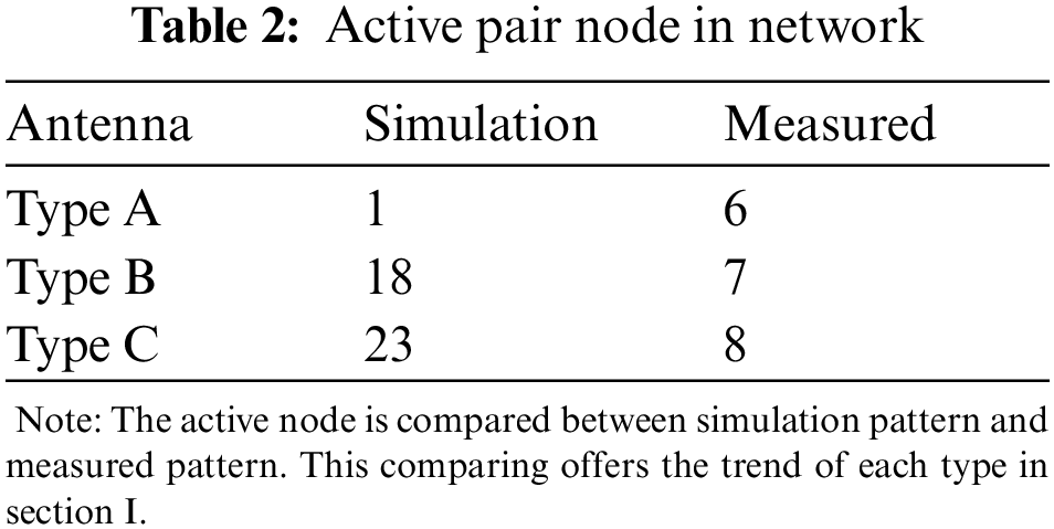

Figure 12: Simulated throughput of the network

Figure 13: Trending of delay in network
To confirm the performance of SDTR system, the constructed prototype is tested in real circumstance. Types A, B and C are assumed as shown in Fig. 14. Two users and one router are assumed in the system. Type A employs omni-directional pattern for both transmitting and receiving modes as a conventional system. Type B employs directional pattern for both modes. Type C employs omni-directional pattern for receiving mode while directional pattern is employed for transmitting mode. The measurement is set up in indoor as shown in Fig. 15. The frequency is 2.45 GHz. The distance between user and router is 5 m. The User 1 starts sending the data to router and then router passes the data to User 2. The throughput is countered when the data transfer is completely finished at User 2 for all cases. The measured throughput for all types is shown in Figs. 16–18. As we can see, Types A and B provide a similar throughput as User 2 has to wait until the communication between User 1 and router finishes, hence the delay still remains. However, Type C (SDTR system) provides the highest throughput over Types A and B. This is because the SDTR systems allow the router to communicate with Users 1 and 2 at the same time. Therefore, the system delay is relatively decreased. Also, this SDTR system can cure the problem of hidden terminal.

Figure 14: Scenario for throughput evaluation for Type A, B and C

Figure 15: Photograph of peer-to-peer scenario

Figure 16: Download throughput in network

Figure 17: Upload throughput in network

Figure 18: Total throughput in network
This paper has introduced the concept to enhance the wireless network performance. The SDTR concept is to employ two different radiation patterns at router, omni-directional for receiving mode and directional for transmitting mode. To decrease the system delay, these two modes are simultaneously operated at the same time. The SDTR concept is a modification on physical layer so that it can be applied for a current MAC protocol. A prototype of SDTR systems has been constructed and tested comparing to the simulation results. The throughput measurement was performed in real circumstances. The obtained results have revealed that the SDTR systems provide a higher throughput and a lower delay comparing to the conventional system. The increased throughput occurs as the systems can tackle the impairments of deafness and hidden terminals. Also, the lower delay is achieved as the SDTR system allows the router to communicate with more than one user at the same time. This paper is limited to one channel testing. Size is also a factor in usability. In the future, we should combine it with a smaller harness such as a Y-junction circulator.
Funding Statement: This work is financially supported from the Thailand Research Fund through the Royal Golden Jubilee Ph.D. program (Grant No.PHD/0118/2558)
Conflicts of Interest: The authors declare that they have no conflicts of interest to report regarding the present study.
1. X. Ding, B. Wang, G. D. Ge and D. Wang, “A broadband VHF/UHF double-whip antenna,” IEEE Transactions on Antennas and Propagation, vol. 60, no. 2, pp. 719–724, 2012. [Google Scholar]
2. V. Deepu, R. K. Raj, M. Joseph, M. N. Suma and P. Mohanan, “Compact asymmetric coplanar strip fed monopole antenna for multiband applications,” IEEE Transactions on Antennas and Propagation, vol. 55, no. 8, pp. 2351–2357, 2007. [Google Scholar]
3. D. L. Wu, G. Zhang, J. F. Li, Y. J. Wu and X. X. Tian, “A Low-profile antenna with omnidirectional and unidirectional radiation patterns over two operation bands,” IEEE Access, vol. 7, pp. 182691–182700, 2019. [Google Scholar]
4. L. Gong, Y. Fu, K. Y. Chan, J. A. Nanzer and R. Ramer, “An SIW horn antenna fed by a coupled mode emulating pyramidal horn antennas,” IEEE Access, vol. 68, no. 1, pp. 33–42, 2020. [Google Scholar]
5. P. Valale Prasannakumar, M. A. Elmansouri and D. S. Filipovic, “Broadband reflector antenna with high isolation feed for full-duplex applications,” IEEE Transactions on Antennas and Propagation, vol. 66, no. 5, pp. 2281–2290, 2018. [Google Scholar]
6. A. Dadgarpour, B. Zarghooni, B. S. Virdee and T. A. Denidni, “One-and two-dimensional beam-switching antenna for millimeter-wave MIMO applications,” IEEE Transactions on Antennas and Propagation, vol. 64, no. 2, pp. 564–573, 2016. [Google Scholar]
7. J. Costa, E. Lima and C. Fernandes, “Compact beam-steerable lens antenna for 60-GHz wireless communications,” IEEE Transactions on Antennas and Propagation, vol. 57, no. 10, pp. 2926–2933, 2009. [Google Scholar]
8. N. Rezazadeh and L. Shafai, “Impact of element pattern symmetry on the effective degrees of freedom in dual-polarized gnss adaptive antenna arrays,” IEEE Transactions on Antennas and Propagation, vol. 66, no. 9, pp. 4669–4677, 2018. [Google Scholar]
9. H. N. Dai, K. W. Ng, M. Li and M. Y. Wu, “An overview of using directional antennas in wireless networks,” International Journal of Communication Systems, vol. 26, no. 4, pp. 413–448, 2011. [Google Scholar]
10. X. Cai and K. Sarabandi, “A compact broadband horizontally polarized omnidirectional antenna using planar folded dipole elements,” IEEE Transactions on Antennas and Propagation, vol. 64, no. 2, pp. 414–422, 2016. [Google Scholar]
11. G. Bianchi, D. Messina, L. Scalia and I. Tinnirello, “A space-division time-division multiple access scheme for high throughput provisioning in WLANs,” in IEEE International Conference on Communications, COEX convention center, Seoul Korea, vol. 4, pp. 2728–2733, 2005. [Google Scholar]
12. B. Alawieh, Y. Zhang, C. Assi and H. Mouftah, “Improving spatial reuse in multihop wireless networks-a survey,” IEEE Communications Surveys and Tutorials, vol. 11, no. 3, pp. 71–91, 2009. [Google Scholar]
13. T. S. Kim, H. Lim and J. C. Hou, “Understanding and improving the spatial reuse in multihop wireless networks,” IEEE Transactions on Mobile Computing, vol. 7, no. 10, pp. 1200–1212, 2008. [Google Scholar]
14. T. Y. Lin and J. C. Hou, “Interplay of spatial reuse and SINR-determined data rates in CSMA/CA-based, multi-hop, multi-rate wireless networks,” IEEE INFOCOM 2007 - 26th IEEE Int. Conf. on Computer Communications, IEEE Computer Society, USA, pp. 803–811, 2007. [Google Scholar]
15. V. Dmitriev and W. Castro, “Dynamically controllable terahertz graphene Y-circulator,” IEEE Transactions on Magnetics, vol. 55, no. 2, pp. 1–12, 2019. [Google Scholar]
16. B. Avser, R. F. Frazita and G. M. Rebeiz, “Interwoven feeding networks with aperture sinc-distribution for limited-scan phased arrays and reduced number of phase shifters,” IEEE Transactions on Antennas and Propagation, vol. 66, no. 5, pp. 2401–2413, 2018. [Google Scholar]
17. R. Singh, A. Sharma and R. Singh, “Power efficient design of multiplexer based compressor using adiabatic logic,” International Journal of Computer Applications, vol. 81, no. 10, pp. 45–50, 2013. [Google Scholar]
18. R. Yazdani, H. Aliakbarian, A. Sahraei and G. A. Vandenbosch, “A compact triple-band dipole array antenna for selected sub 1 GHz, 5G and WiFi access point applications,” IET Microwaves, Antennas and Propagation, vol. 15, no. 15. pp. 1866–1876, 2021. [Google Scholar]
19. N. Nie, X. Yang, Z. N. Chen and B. Wang, “A Low-profile wideband hybrid metasurface antenna array for 5G and WIFI systems,” IEEE Transactions on Antennas and Propagation, vol. 68, no. 2, pp. 665–671, 2020. [Google Scholar]
20. P. Mathur, R. Augustine, M. Gopikrishna and S. Raman, “Dual MIMO antenna system for 5G mobile phones, 5.2 Ghz WLAN, 5.5 GHz WiMAX and 5.8/6 GHz WIFI applications,” IEEE Access, vol. 9, pp. 106734–106742, 2021. [Google Scholar]
21. O. Singh, V. K. Verma and S. L. Tyagi, “Algorithm for frequency division multiple and time division multiple access schemes,” European Journal of Molecular and Clinical Medicine, vol. 8, no. 1, pp. 1282–1288, 2021. [Google Scholar]
22. A. Sarin and A. Avestruz, “A framework for code division multiple access wireless power transfer,” IEEE Access, vol. 9, pp. 135079–135101, 2021. [Google Scholar]
23. P. M. Shah, S. S. Qureshi, R. A. Butt, S. Mahdaliza Idrus and J. Mirza, “Design and analysis of 5G network architecture with orthogonal frequency division multiple access based passive optical network,” Optical Fiber Technology, vol. 67, pp. 102678, 2021. [Google Scholar]
24. H. Yin and S. Alamouti, “OFDMA: A broadband wireless access technology,” 2006 IEEE Sarnoff Symposium, Princeton, NJ, USA, pp. 1–4, 2006. [Google Scholar]
25. J. M. Hamamreh, M. Abewa and J. P. Lemayian, “New non-orthogonal transmission schemes for achieving highly efficient, reliable, and secure multi-user communications,” RS Open Journal on Innovative Communication Technologies, vol. 1, no. 2, pp. 12, 2020. [Google Scholar]
26. S. Karatepe, M. Kirik and J. M. Hamamreh, “Novel nonorthogonal multi-access method for multi-user MIMO with antenna number modulation,” RS Open Journal on Innovative Communication Technologies, vol. 2, no. 3, pp. 1–11, 2021. [Google Scholar]
27. B. Clerckx, Y. Mao, R. Schober, E. A. Jorswieck, D. J. Love et al., “Is NOMA efficient in multi-antenna networks? a critical look at next generation multiple access techniques,” IEEE Open Journal of the Communications Society, vol. 2, pp. 1310–1343, 2021. [Google Scholar]
28. K. Kosek-Szott, “A survey of MAC layer solutions to the hidden node problem in ad-hoc networks,” Ad Hoc Networks, vol. 10, no. 3, pp. 635–660, 2012. [Google Scholar]
29. A. P. Subramanian and S. R. Das, “Addressing deafness and hidden terminal problem in directional antenna based wireless multi-hop networks,” Wireless Networks, vol. 16, no. 6, pp. 1557–1567, 2008. [Google Scholar]
30. S. Chakraborty, S. Nandi and S. Chattopadhyay, “Alleviating hidden and exposed nodes in high-throughput wireless mesh networks,” IEEE Transactions on Wireless Communications, vol. 15, no. 2, pp. 928–937, 2016. [Google Scholar]
31. F. Babich and M. Comisso, “Throughput and delay analysis of 802.11-based wireless networks using smart and directional antennas,” IEEE Transactions on Communications, vol. 57, no. 5. pp. 1413–1423, 2009. [Google Scholar]
32. M. Mehrnoush, V. Sathya, S. Roy and M. Ghosh, “Analytical modeling of Wi-fi and LTE-LAA coexistence: Throughput and impact of energy detection threshold,” IEEE/ACM Transactions on Networking, vol. 26, no. 4, pp. 1990–2003, 2018. [Google Scholar]
33. R. Yin, G. Y. Li and A. Maaref, “Spatial reuse for coexisting LTE and Wi-fi systems in unlicensed spectrum,” IEEE Transactions on Wireless Communications, vol. 17, no. 2, pp. 1187–1198, 2018. [Google Scholar]
34. Z. Tang, X. Zhou, Q. Hu and G. Yu, “Throughput analysis of LAA and Wi-fi coexistence network with asynchronous channel access,” IEEE Access, vol. 6, pp. 9218–9226, 2018. [Google Scholar]
35. L. Xiong and G. Mao, “Saturated throughput analysis of IEEE 802.11e EDCA,” Computer Networks, vol. 51, no. 11, pp. 3047–3068, 2007. [Google Scholar]
36. J. Simo Reigadas, A. Martinez-Fernandez, J. Ramos-Lopez and J. Seoane-Pascual, “Modeling and optimizing IEEE 802.11 DCF for long-distance links,” IEEE Transactions on Mobile Computing, vol. 9, no. 6, pp. 881–896, 2010. [Google Scholar]
 | This work is licensed under a Creative Commons Attribution 4.0 International License, which permits unrestricted use, distribution, and reproduction in any medium, provided the original work is properly cited. |