DOI:10.32604/cmc.2022.025122
| Computers, Materials & Continua DOI:10.32604/cmc.2022.025122 | |
| Article |
A Modified-Simplified MPPT Technique for Three-Phase Single-State Grid-Connected PV Systems
Department of Electrical Engineering, Faculty of Engineering, Rajamangala University of Technology Thanyaburi, Pathum Thani, 12110, Thailand
*Corresponding Author: Boonyang Plangklang. Email: boonyang.p@en.rmutt.ac.th
Received: 12 November 2021; Accepted: 24 January 2022
Abstract: Nowadays, the single state inverter for the grid-connected photovoltaic (PV) systems is becoming more and more popular as they can reduce circuit complexity resulting in less power losses of the inverter. This paper focuses on the use of model predictive control (MPC) to control a 3-phase and 2-level single-state grid-connected inverter in order to regulate the PV maximum power point (MPP). The algorithm of MPC scheme was done to measure the simultaneous current signal including predicting the next sampling current flow. The reference current (Id*) was used to control the distribution of electrical power from the solar cell to the grid. To be able to control the maximum power point tracking (MPPT) when the sunlight suddenly changes, so that a developing MPPT based on estimation current perturbation and observation (ECP&O-MPPT) technique was used to control the reference current. This concept was experimented by using MATLAB/Simulink software package. The proposed technique was tested and compared with the old technique. The simulation results showed that the developed MPPT technique can track the MPP faster when the light changes rapidly under 1,000 W/m2, 25°C standard climatic conditions. The MPPT time was 0.015 s. The total harmonic distortion (THD) was 2.17% and the power factor was 1.
Keywords: Single-state grid-connected; model predictive control; maximum power point; estimation perturbation and observation
Today, renewable energy technologies are developing rapidly. Solar cells are a rapidly evolving renewable energy source and play an important role in clean energy use [1–3]. Because the energy that comes from sunlight alone is endless. It is also environmentally friendly. No carbon dioxide is released into the atmosphere. This is in line with the agreement to reduce carbon dioxide emissions to reduce global warming [4]. Currently, many countries have tariffs on imported goods based on their carbon dioxide emission rates [5,6]. For this reason, we focus on cleanliness and the environment to avoid fossils and other sources that are harmful to the environment. Solar energy is one of the most widely used sources of natural energy [7,8]. It stems from the rapid development of photovoltaic technology in recent years that has improved efficiency and reliability. However, commercial PV panels require a large area. Therefore, it has an impact on the environment and agricultural areas. So, another solution is to install it on the rooftop (solar rooftop), on the dam and on the lake (floating solar). The problem with PV systems is that the rapid change in radiation, temperature and partial shading of the panels. Another problem is the installation of PV panels on the rooftop in a position that does not correspond to the sun's orbit.
Therefore, MPPT is used to solve all the problems mentioned above. It is also used to optimize photovoltaic systems. There are several ways to track the MPP, such as perturbation and observation (P&O), increment conductance (INC), fuzzy logic (FL), particle swarm optimization (PSO) and the hybrid. The P&O and INC are traditional methods. This method is good at tracking MPP in stable environments [9–12]. The FL method can reduce oscillations around the MPP. The downside is the difficult design [13,14]. The PSO is the best suitable algorithm under partial shading. The disadvantage of this approach is the delay in tracking the MPP [15,16]. The hybrid MPPT technique offers accurate and efficient tracking under rapidly changing environmental conditions. However, this method is complex [17].
So that the PV system produces the MPP. It must be connected to a direct current to direct current (DC–DC) or direct current to alternative current (DC–AC) converter using the aforementioned algorithm to track and control the MPP. Other parts of the photovoltaic system include inverters, controllers, and sensors, which play a key role in harnessing electrical power to the grid. The basic functions for all grid-connected inverters e.g., THD, grid voltage disturbances, grid voltage variations, MPPT and partial shading detection, operation at unity power factor as required by standards, fast voltage detection and fast frequency detection. The THD is limited and imposed by the standard. The MPPT must have very high efficiency in steady-state, fast-tracking during rapid irradiation changes and stable operation at very low irradiation levels. Currently, PV applications can be divided into two main categories, stand-alone systems and grid connected systems. The stand-alone systems are typically used in low power systems such as residential applications. Therefore, battery banks are needed to store the energy produced by PV panels. Grid-connected systems are ideal for injecting maximum power drawn from the PV system to the grid, even when temperatures and radiation levels change. The grid-connected inverter is divided into single-stage and two-stage. The single-stage system connects directly between the array sides and the inverter side as shown in Fig. 1a. The two-stage system requires a DC–DC converter to connect the PV array into the inverter side as shown in Fig. 1b. Two systems configuration plays an important role in converting from DC–AC.
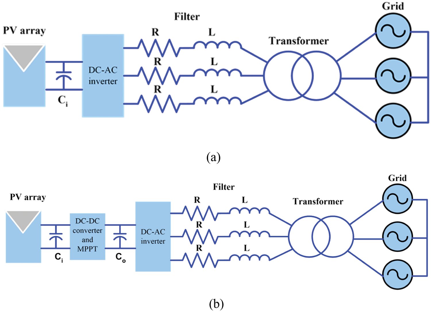
Figure 1: PV grid-connected system (a) single stage and (b) two stages
An important component of a PV system is the grid-connected system. The grid-connected systems are ideal for injecting maximum power drawn from the PV system to the grid. There are several ways to control the current of grid-connected inverters, such as proportional-integral controller (PI), proportional-resonance controller (PR). PI-based current control implemented in a synchronous frame is commonly used in three-phase converters [18]. In single-phase converters, the PI controller capability to track a sinusoidal reference is limited and PR can offer better performances [19].
The basic functions for all grid-connected inverters are THD [20], grid voltage disturbances, grid voltage variations, maximum power point tracking, partial shading detection, operation at unity power factor as required by standards, fast voltage detection and fast frequency detection. The THD is limited and imposed by the standard. The MPPT must have very high efficiency in steady-state, fast-tracking during rapid irradiation changes and stable operation at very low irradiation levels.
In the literature review, various models are used for designing a controller to control voltage, current, MPP, THD and power factor (p.f.) to meet standards as shown in Tab. 1.
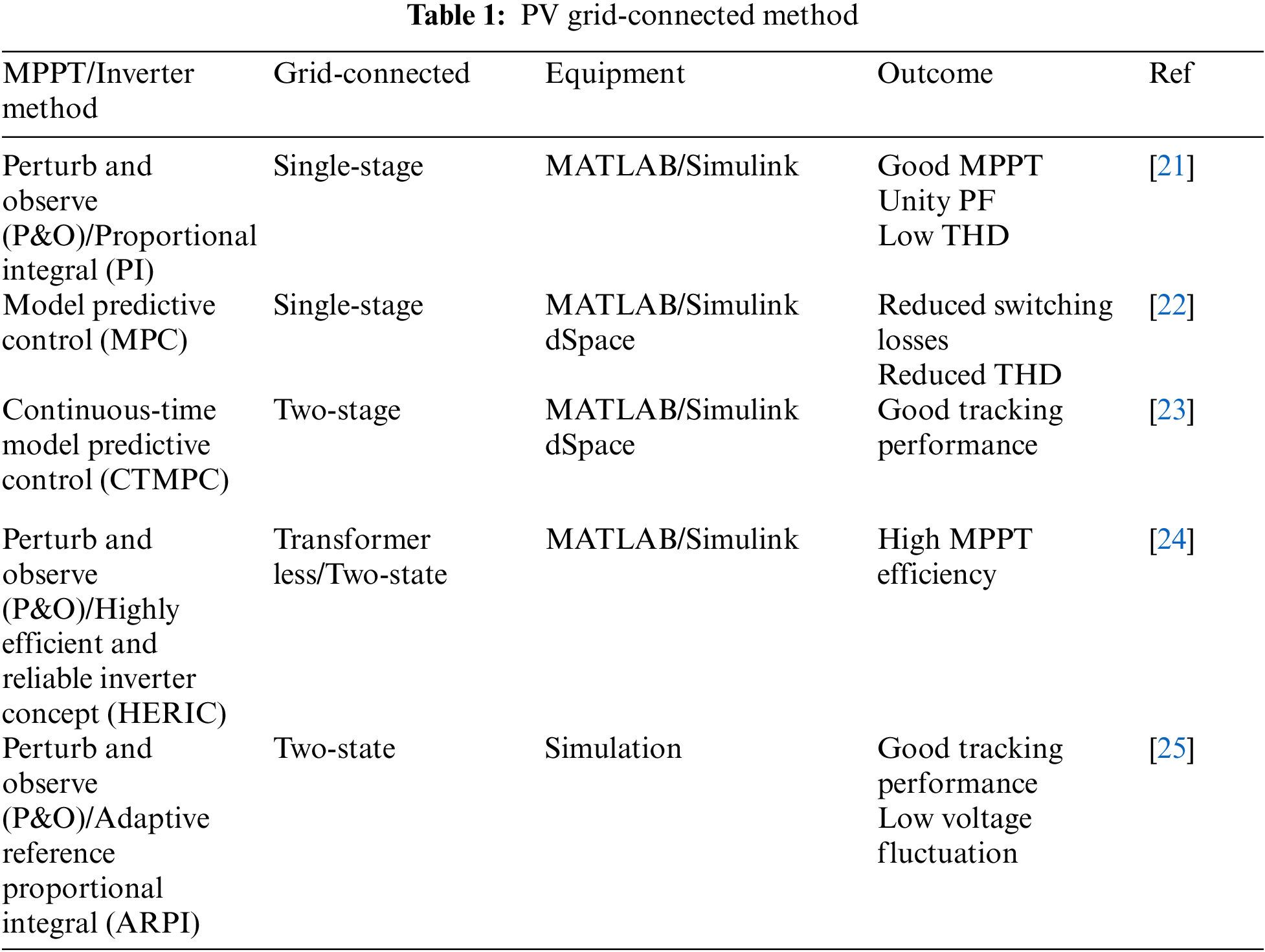
Several papers were proposed on P&O/PI, MPC, CTMPT, P&O/HERIC and P&O/AERPI. The purpose is to enable the system to rapidly track MPP when irradiation levels and temperatures change rapidly. The P&O method is still popular for MPPT. However, all of the above methods have been able to keep track of MPP very well. The THD and voltage fluctuation are low.
Today, the MPC are widely used such as motor drives and grid-connected inverter. Because it is a simple method, robustness and fast-dynamic response. Unlike classic linear controls such as PI, PR, this approach can be used to isolate the dependent control loop and ultimately improve the dynamic response. The MPC method is a control system that can control the injection of current into the grid. The grid current is measured to calculate pre-time current. Subsequently, the current at time t + 1 is calculated. The values are then estimated from the output voltage vector of the 3-phase and 2-levels inverter. After each vector with all different output voltages is computed. The correct gate-drive signal is then generated. Therefore, the MPC is suitable for use under non-linear system conditions.
This paper proposes a suitable control method for single-state grid-connected inverters. Additionally, the ECP&O-MPPT algorithm has been optimized to track the MPP faster. The MPP can be tracked immediately when the irradiation changes suddenly. Where, the ECP&O is used to generate the PV output current reference corresponding to the MPPT. Then, the MPC is used to maintain the PV output current corresponding to the referent current and provide the inverter control signal. As a result, the reliability and efficiency of this system are increased. In addition, this study also included a contribution to the literatures related to reducing the number of power semiconductors. The developed system effectively controls the voltage, current, MPPT, THD and power factors.
This paper is organized as follows. Section 2 described the grid-connected inverter modeling and configuration. Section 3 devoted to maximize power point tracking and inverter design. The simulation results and conclusion were discussed in Sections 4 and 5, respectively.
2 Grid-connected Inverter Modeling and Configuration
The SPR-315E-WHT-D PV were used in this simulation. Eleven series modules and two parallel strings were used. The parameters of PV panel are illustrated in Tab. 2. The IV and PV characteristics under various irradiations at 25°C are shown in Fig. 2.
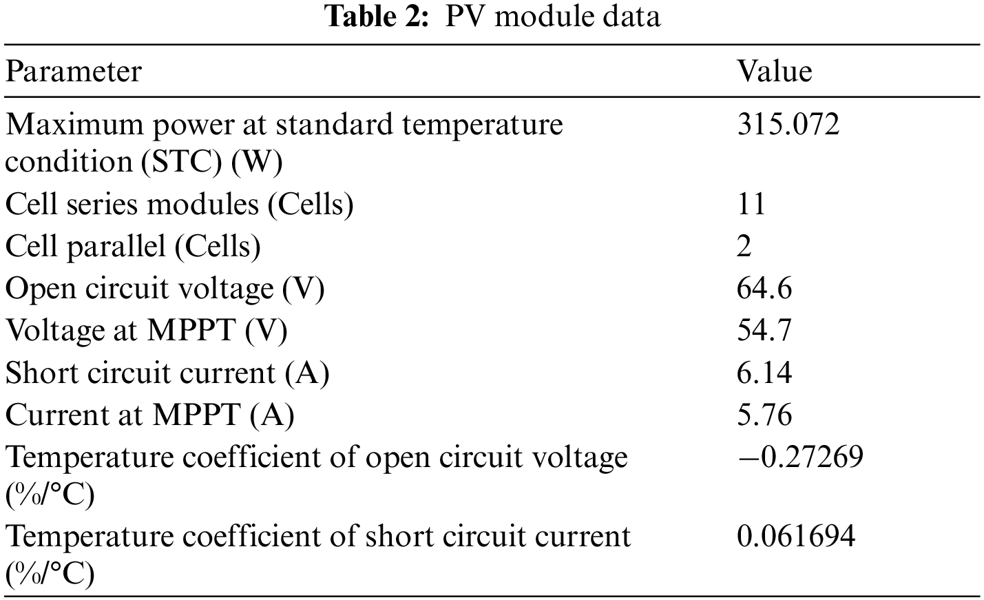
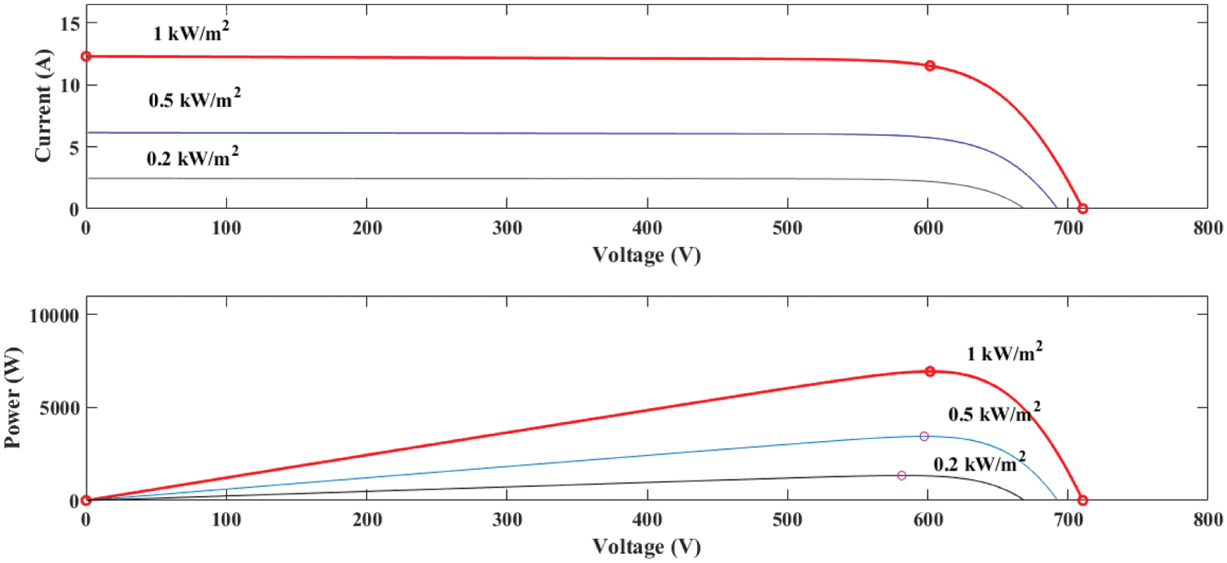
Figure 2: IV and PV characteristics of PV panel at 25°C and vary irradiations
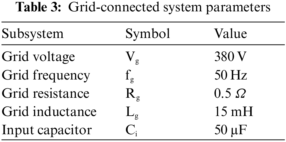
The simple structure of three phase grid-connected inverter is shown in Fig. 3. The system consists of PV panel, 3-phase inverter, grid impedance (Rg and Lg) and 3-phase grid. The parameters of the system are illustrated in Tab. 3.
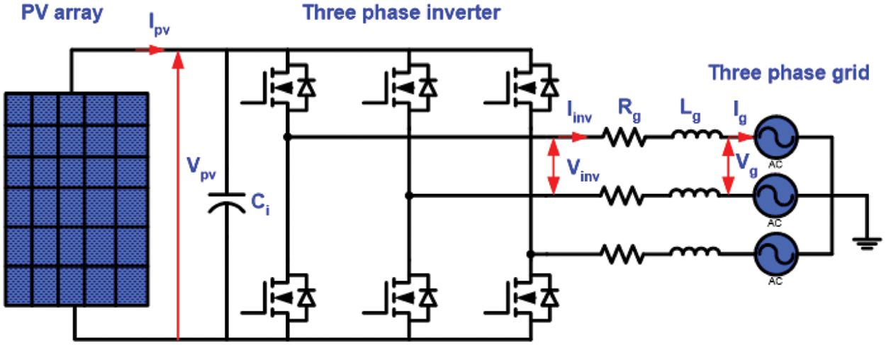
Figure 3: Basic three phase grid-connected inverter schematic diagram
To track the MPP with a simple and faster than the P&O method, Eq. (1) thus gives rise to a new method known as the ECP&O method. It is shown in Fig. 4. The ECP&O method works as a period. By compare of photovoltaic power at the current time with the previous period. If the rate of change in power is positive, the system will adjust the command current in the same direction. If the rate of change in power is negative, the system will adjust the command current in the opposite direction. The advantages are simple and uncomplicated. Therefore, ECP&O was used to control the Id* of the inverter.

Figure 4: ECP&O MPPT algorithm flowchart
where
Idinit = initial command current
Impp = current at maximum power
Irr = measurement of irradiation
The MPC was used in the control of inverter. It was a theoretical approach to apply for grid connected inverters. The theory was presented by referring to the control of the electric drive system to study and easy to understand the application as shown in Fig. 5.

Figure 5: Block diagram of model predictive control
Basically, the number is limited by the number of possible states of the constant power supply, that from the status of the power converter operation, in which the above process allows to predict the next time status [26]. The predicted values calculated the state of the correct switching action and was selected by the cost function [27]. The control technique can be summarized as follows:
1. Set the equation cost function.
2. Create inverter model and switch design of switch equipment.
3. Create models for prediction.
The purpose of MPC is to limit the error between the measured current and the reference current. A cost function can be written in the form of a perpendicular axis [28]. A measurement of the error between reference and measured values is shown in Eq. (2).
where
The value of the load vector was used to determine the voltage vector. This predicted current was used for the load model. The principles of predicting the current of an inverter, it can be determined by the voltage drop and the grid voltage, as shown in Fig. 6. The filter (L-filter) can be determined by solving Eqs. (5) and (6). However, the L-filter can be adjusted. Because the variations in the L-filter values can affect the performance of MPC in terms of the root mean square of grid-currents. The fast dynamic response is not affected.

Figure 6: Equivalent circuit of inverter connection
The prediction of the load current in the discrete model of the model can be explained by Eq. (3).
where V is the inverter output voltage vector, i is the load current vector and e is the back-emf voltage vector.
Eq. (3) can be represented by a discrete-time estimation function. Ts is the sampling time. It is shown in Eq. (4).
By substitute Eq. (4) into Eq. (3), then Eqs. (5) and (6) are obtained as follow:
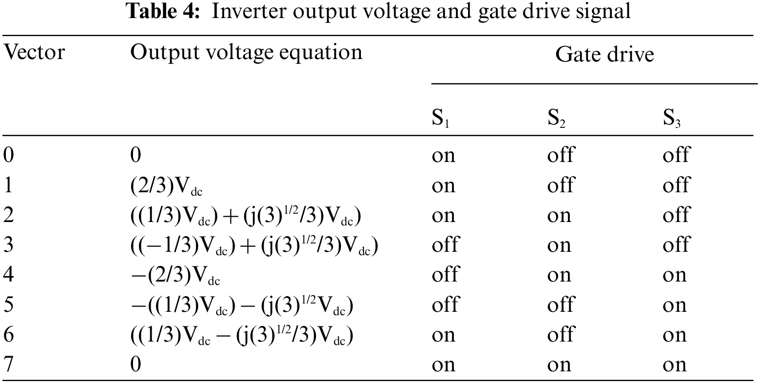
Eq. (6) was used to predict the load current that will occur in the next order by comparing with the reference current i*(k) of the system. To analyzing the output voltage of a 3-phase inverter, it is a complex method that can be expressed by the voltage vector of a 3-phase and 2-level. The inverters module is represented by the state of the two-state switch: on and off (Si1, Si2 Si3 = a, b, c). When a, b, c is the phase voltage. The 3-phase system can be used to determine the gate drive signal by Eq. (7).
In order to generate the 3-phase inverter output signal from the control signals Sa, Sb and Sc. It can be seen that the conversion of the direct current (DC) to the alternative current (AC) with a simple mathematical equation. It can be summarized as the Eq. (8). The flowchart of model predictive control algorithm is shown in Fig. 7. The state of the signal generator is shown in Tab. 4.

Figure 7: Model predictive control algorithm flowchart
In order to test the performance of the maximum power point tracking of the proposed algorithms, the tests were compared with the increment conductance and the traditional perturbation and observation. The simulation system and controllers schematic diagram of the grid-connected inverter is shown in Fig. 8. The system consists of PV panel, 3-phase inverter, 3-phase grid, controller and sensor.

Figure 8: Simulation system and controllers schematic diagram of the grid-connected inverter
Fig. 9 shows the simulation diagram of the ECP&O MPPT and MPC grid-connected. The solar irradiation sensor converts the light intensity to the referent initial current (Idint). The PV voltage (Vpv), PV current (Ipv) and Idint are processed by the MPPT controller. The reference current (Idref) is forwarded to the MPC. The MPC grid-connected consists of four signal input sources. The reference current input and the grid current input are used to calculate and predict the current to generate the Sa, Sb and Sc gate drive signals. Both of these variables are required to convert from a 3-phase system into a 2-phase reference (αβ). Fig. 10 shows a simulation diagram of a 3-phase system to a 2-phase reference (αβ). Vg and Vdc are the reference grid voltage and reference PV voltage. The MPC is in the form of an S-Function. The principle of MPC is shown in Fig. 11. The diagram shows the position of the current vector (iα). This consists of reference current (i*) or iref, actual current (i) or ik and predictive current (ip) or i(k + 1), then predicts the current value at the operating state of the gate drive signal to control the 3-phase inverter. Thus, the MPC operates in the correct position and corresponds to the voltage vector V(k).

Figure 9: Simulation diagram of the MPPT and MPC grid-connected

Figure 10: Simulation diagram of a 3-phase system to a 2-phase reference (αβ)

Figure 11: Principle of electric current prediction from current vector
Two following operating conditions were used to check the algorithm performances in the grid-connected system:
1. 1,000 W/m2, 25°C standard climatic conditions,
2. Rapidly changes in solar irradiation.
To demonstrate the performance of the proposed method. The MPPT under standard climate is tested. Fig. 12 shows the comparison of PV output power. The MPPT time of the proposed is 0.015 s. The proposed method tracks the MPP fastest. Fig. 13 shows the comparison of the Idref. The oscillation of the proposed method is minimal. Fig. 14 shows the comparison of the grid current waveforms. Obviously, the proposed method allows the system to track the peak current as quickly as possible. Fig. 15 shows the comparison of the THD. The comparison shows the performance of the proposed MPPT. The THD of the proposed is the lowest. In comparison, the proposed method is best suited for the MPC grid-connected.

Figure 12: Comparatives of PV array power under standard climatic condition

Figure 13: Comparatives of Idref under standard climatic condition
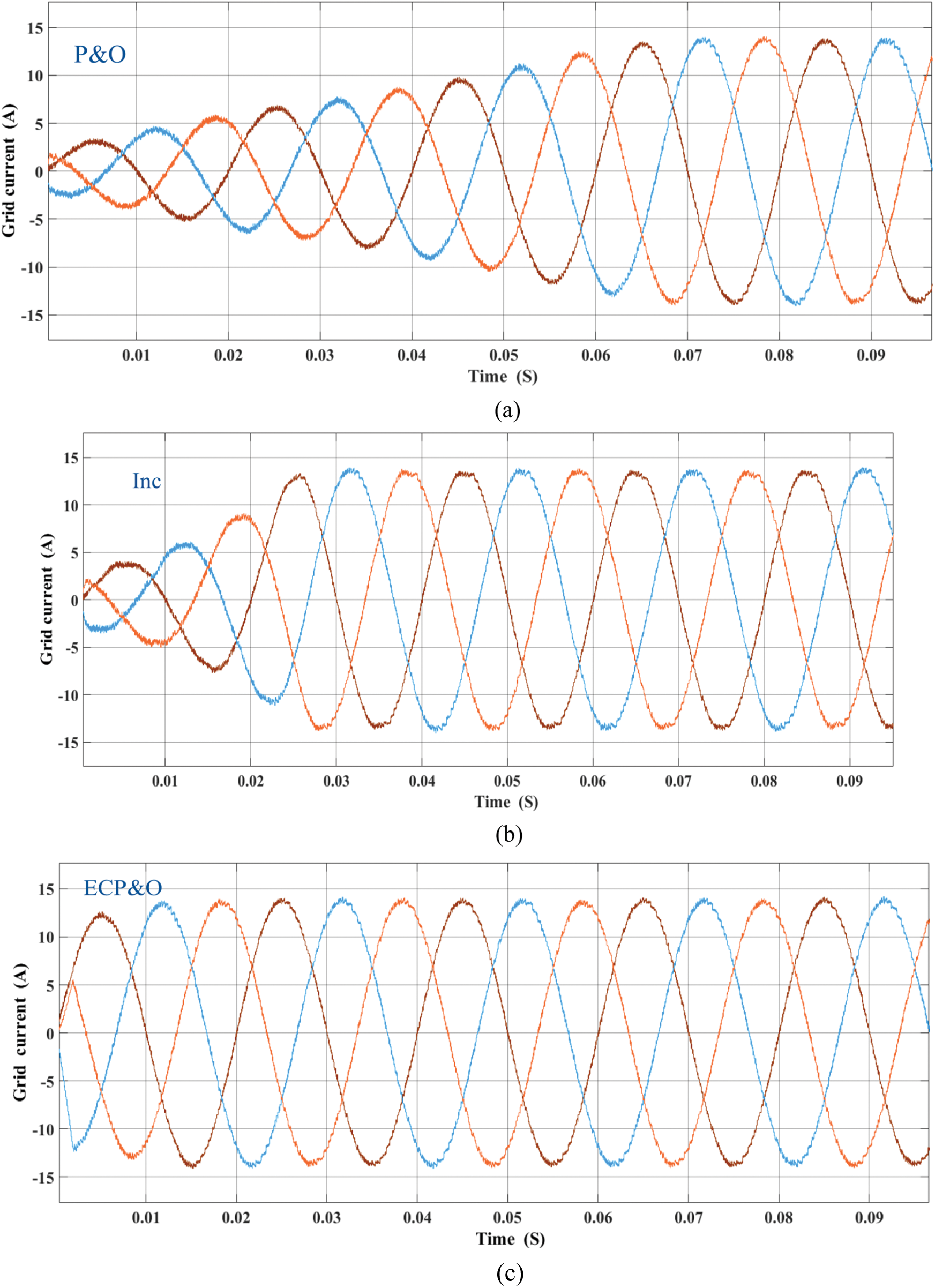
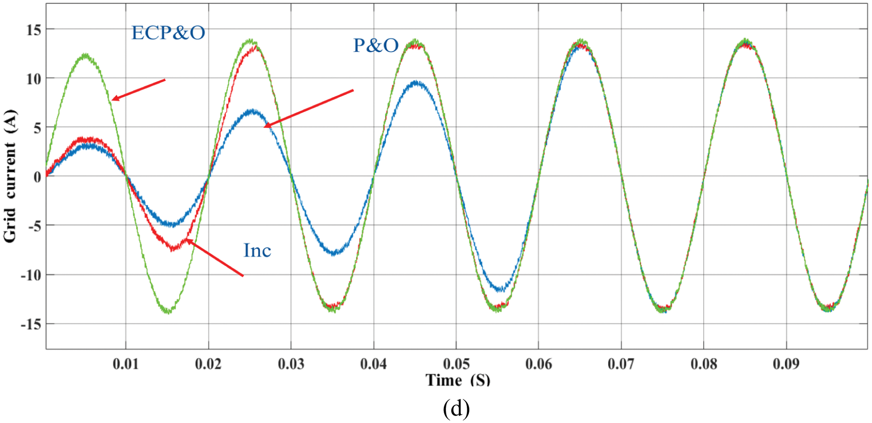
Figure 14: Comparatives of grid current under standard climatic condition (a) P&O (b) INC (c) ECP&O (d) overall comparatives

Figure 15: Comparatives of THD under standard climatic condition
To verify the performance of the proposed PV grid-connected system. The system was tested under rapid changes in solar radiation. The comparison result is shown in Fig. 16. By comparison, it is clearly seen that initially at the 1000 W/m2 radiation level. The proposed algorithm tracks the maximum power point the fastest. The second is the INC algorithm. The last order is the P&O algorithms. While the irradiation is rapidly dropped to 200 W/m2. The MPPT of all algorithms was also able to track the MPP. This demonstrates the performance of the MPC grid-connected algorithm. However, the proposed algorithm has the least oscillation around the maximum power point. Where the irradiation is rapidly increased from 200 to 500 W/m2. The most performance MPPT algorithm is the proposed algorithm.
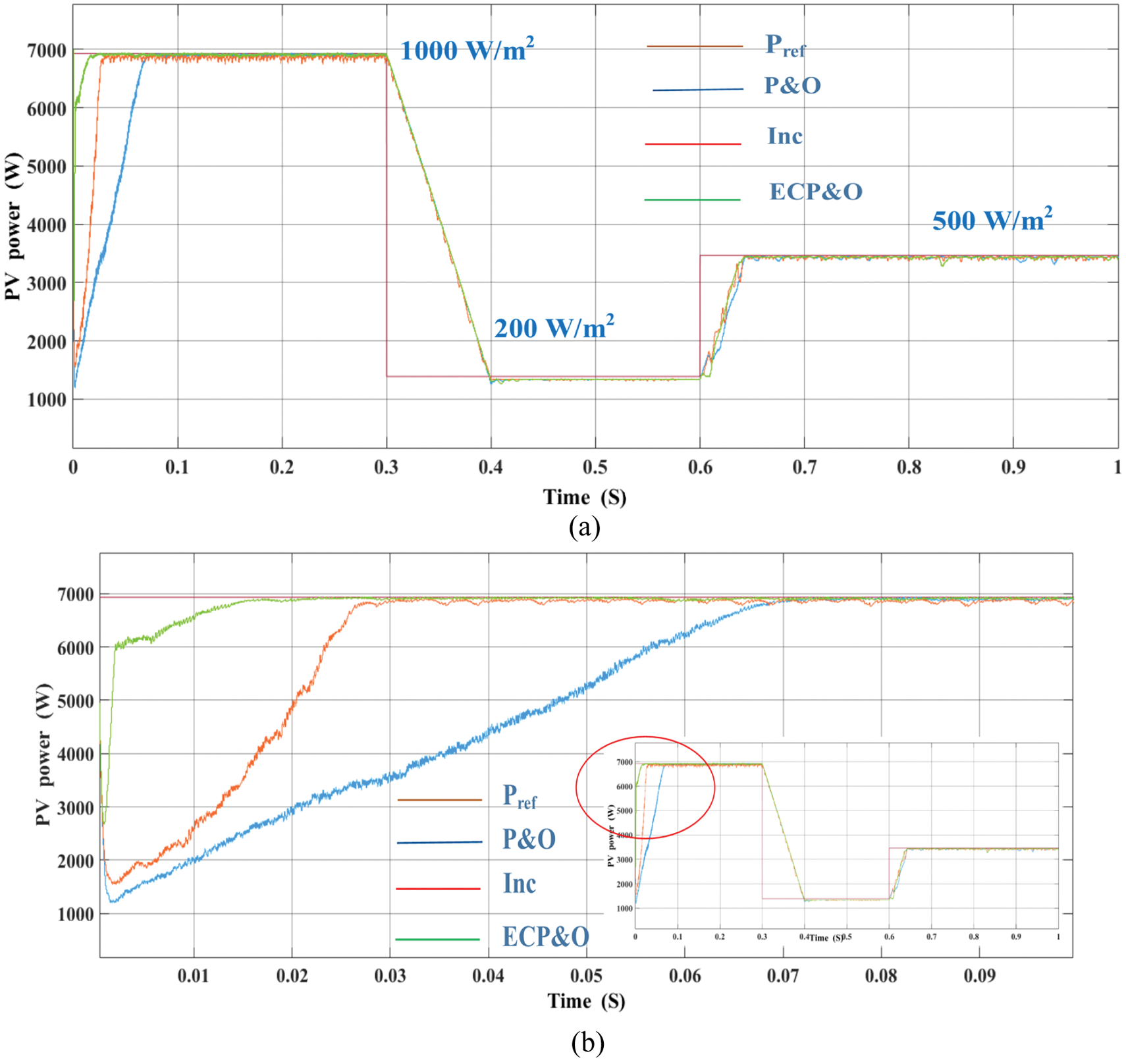
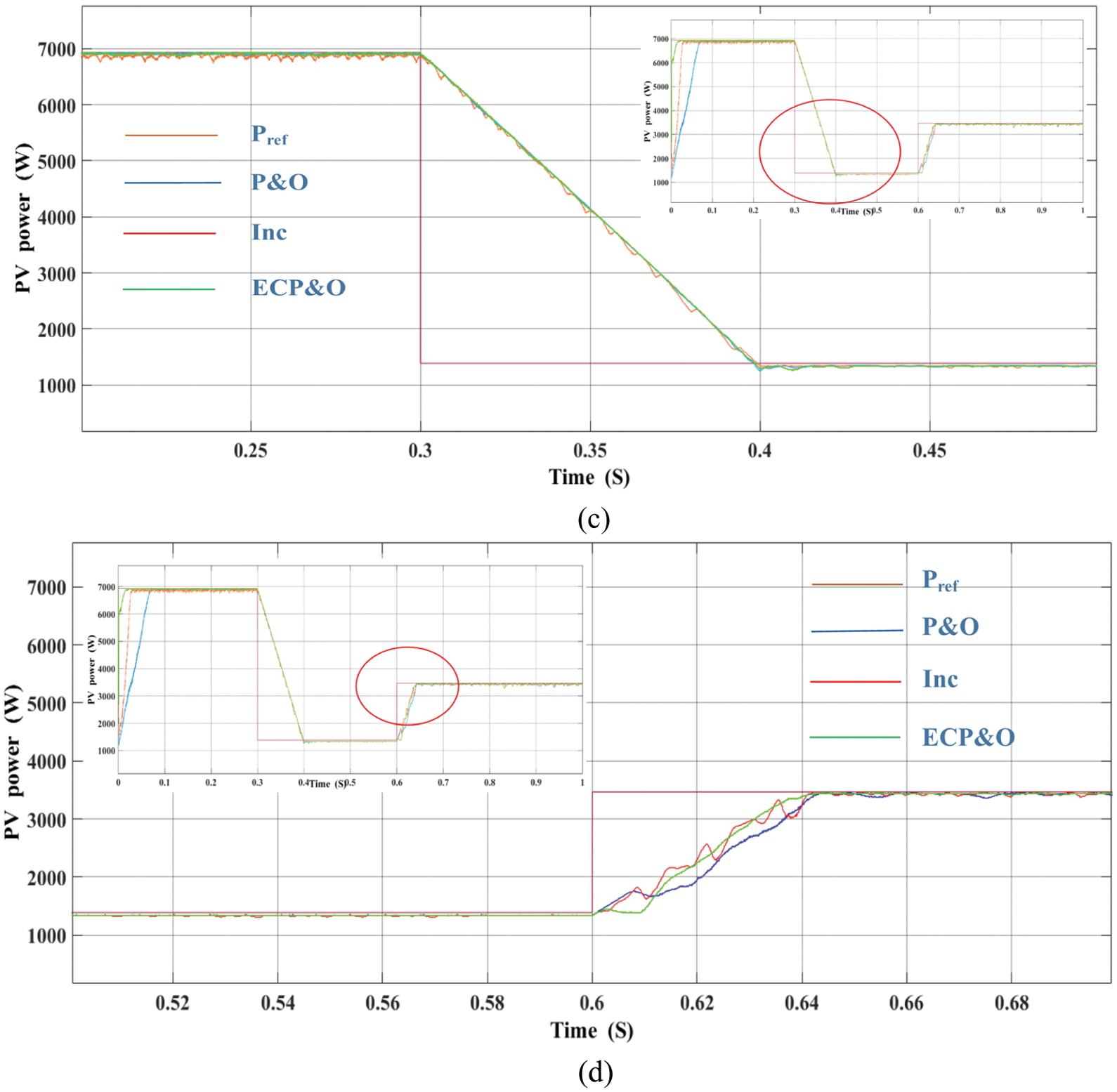
Figure 16: Comparatives of PV array power under rapidly changes in solar irradiation (a) overall comparatives (b) 1000 W/m2 (c) 200 W/m2 (d) 500 W/m2
Fig. 17 shows the comparatives of grid current under rapid changes in solar irradiation. The simulation results show that the proposed algorithm is capable of tracking current at MPPT quickly. The grid current waveform under the rapid change in solar radiation of the P&O, INC and ECP&O algorithms is shown in Fig. 18. It has been shown that under rapid changes in radiation. The ECP&O algorithm has the best performance due to its most sinusoidal signal characteristics. As a result, the THD is the lowest as shown in Fig. 19. The THD of ECP&O algorithm is 2.17%. Fig. 20 shows a comparison between Vg and Ig of all MPPT algorithms that the system has a unity power factor.
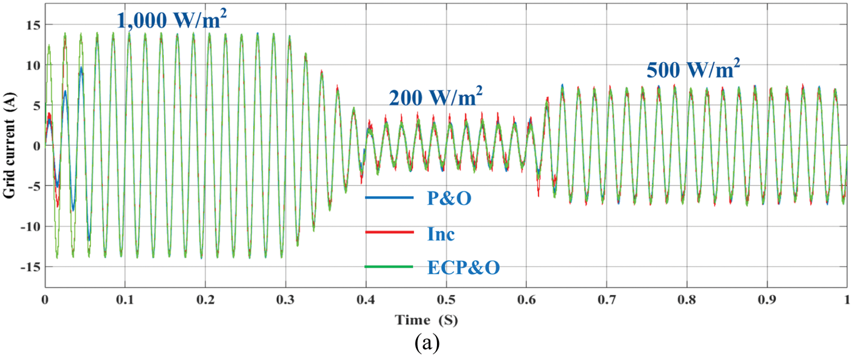

Figure 17: Comparatives of grid current under rapidly changes in solar irradiation (a) overall (b) 1,000 W/m2 (c) 200 W/m2 (d) 500 W/m2

Figure 18: Grid current waveforms under rapidly changes in solar irradiation

Figure 19: Comparatives of THD under rapidly changes in solar irradiation

Figure 20: Vg and Ig under rapidly changes in solar irradiation
This study examines the efficiency and characteristics of a single-state grid-connected inverter. The ECP&OMPPT algorithm is proposed to control the current injected into the grid. The efficiency of the inverter was determined with the ECP&O and MPC algorithms. The simulation results show that the system efficiency corresponds to injected currents into the grid. The THD was standardized and unity power factor. This paper attempts to improve the grid-connected inverter to simplify control, reduce power loss in converters, fast-tracking maximum power point when irradiation changes rapidly, and maintain THD levels within standards. By comparing all the reference current control algorithms, it was found that ECP&O is the most suitable for the MPC algorithm as it provides the best tracking for MPPT. From the simulation results, it can be concluded that the MPC algorithm is suitable for the PV system grid-connected inverters. As can be seen from the grid currents are usually sinusoidal, unity power factor and minimal THD. By compassion with the MPC method as shown in Tab. 1, in comparison, the proposed method has lower total harmonic distortion. It also has a lower oscillation of the power around the MPP. However, the MPC method is suitable only for a simple MPPT method. If it was used with complex MPPT methods, the power oscillations around the MPP and the THD might be too high.
Acknowledgement: This research is supported by the MATLAB/Simulink, Rajamangala University of Technology Rattanakosin. The authors would like to thank Department of Electrical Engineering, Faculty of Engineering, Rajamangala University of Technology Thanyaburi for strong support on the laboratory instruments.
Funding Statement: The authors received no specific funding for this study.
Conflicts of Interest: The authors declare that they have no conflicts of interest to report regarding the present study.
1. M. Usman Khan, K. M. Hasan, A. Faisal Murtaza, H. M. Usman and H. A. Sher, “A robust MPPT control based on double ended forward converter architecture,” Computers, Materials & Continua, vol. 70, no. 1, pp. 135–150, 2022. [Google Scholar]
2. M. Y. Ali Khan, H. Liu, Z. Yang and X. Yuan, “A comprehensive review on grid connected photovoltaic inverters, their modulation techniques, and control strategies,” Energies, vol. 13, no. 16, pp. 4185, 2020. [Google Scholar]
3. M. A. Ebrahim, A. Osama, K. M. Kotb and F. Bendary, “Whale inspired algorithm based MPPT controllers for grid-connected solar photovoltaic system,” Energy Procedia, vol. 162, pp. 77–86, 2019. [Google Scholar]
4. K. -Y. Lo and Y. -M. Chen, “Design of a seamless grid-connected inverter for microgrid applications,” IEEE Transactions on Smart Grid, vol. 11, no. 1, pp. 194–202, 2020. [Google Scholar]
5. D. Pilakkat and S. Kanthalakshmi, “Single phase PV system operating under partially shaded conditions with ABC-PO as MPPT algorithm for grid connected applications,” Energy Reports, vol. 6, pp. 1910–1921, 2020. [Google Scholar]
6. A. Rizqiawan, P. Hadi and G. Fujita, “Development of grid-connected inverter experiment modules for microgrid learning,” Energies, vol. 12, no. 3, pp. 476, 2019. [Google Scholar]
7. L. Guo, N. Jin, Y. Li and K. Luo, “A model predictive control method for grid-connected power converters without AC voltage sensors,” IEEE Transactions on Industrial Electronics, vol. 68, no. 2, pp. 1299–1310, 2021. [Google Scholar]
8. M. M. Samy, M. I. Mosaad, M. F. El-Naggar and S. Barakat, “Reliability support of undependable grid using green energy systems: Economic study,” IEEE Access, vol. 9, pp. 14528–14539, 2021. [Google Scholar]
9. M. Mokhlis, M. Ferfra and R. Idrissi, “High gain observer-based control for grid-connected PV system under partial shading effect,” International Journal of Intelligent Engineering and Systems, vol. 13, no. 2, pp. 161–172, 2020. [Google Scholar]
10. M. Farhat, O. Barambones and L. Sbita, “A real-time implementation of novel and stable variable step size MPPT,” Energies, vol. 13, no. 18, pp. 4668, 2020. [Google Scholar]
11. J. Macaulay and Z. Zhou, “A fuzzy logical-based variable step size P&O MPPT algorithm for photovoltaic system,” Energies, vol. 11, no. 6, pp. 1340, 2018. [Google Scholar]
12. F. A. Banakhr and M. I. Mosaad, “High performance adaptive maximum power point tracking technique for off-grid photovoltaic systems,” Scientific Reports, vol. 11, pp. 20400, 2021. [Google Scholar]
13. S. Bhattacharyya, D. S. Kumar P, S. Samanta and S. Mishra, “Steady output and fast tracking MPPT (SOFT-MPPT) for P&O and Inc algorithms,” IEEE Transactions on Sustainable Energy, vol. 12, no. 1, pp. 293–302, 2021. [Google Scholar]
14. X. Ge, F. W. Ahmed, A. Rezvani, N. Aljojo, S. Samad et al., “Implementation of a novel hybrid BAT-fuzzy controller based MPPT for grid-connected PV-battery system,” Control Engineering Practice, vol. 98, pp. 104380, 2020. [Google Scholar]
15. M. A. Abdullah, T. Al-Hadhrami, C. W. Tan and A. H. Yatim, “Towards green energy for smart cities: Particle swarm optimization based MPPT approach,” IEEE Access, vol. 6, pp. 58427–58438, 2018. [Google Scholar]
16. J. Ahmed and Z. Salam, “An enhanced adaptive P&O MPPT for fast and efficient tracking under varying environmental conditions,” IEEE Transactions on Sustainable Energy, vol. 9, no. 3, pp. 1487–1496, 2018. [Google Scholar]
17. M. Jiang, M. Ghahremani, S. Dadfar, H. Chi, Y. N. Abdallah et al., “A novel combinatorial hybrid SFL–PS algorithm based neural network with perturb and observe for the MPPT controller of a hybrid PV-storage system,” Control Engineering Practice, vol. 114, pp. 104880, 2021. [Google Scholar]
18. H. Liao, X. Zhang and Z. Ma, “Robust dichotomy solution-based model predictive control for the grid-connected inverters with disturbance observer,” CES Transactions on Electrical Machines and Systems, vol. 5, no. 2, pp. 81–89, 2021. [Google Scholar]
19. S. Barcellona, M. Barresi and L. Piegari, “MMC-based PV single-phase system with distributed MPPT,” Energies, vol. 13, no. 15, pp. 3964, 2020. [Google Scholar]
20. X. Chen, X. Ruan, D. Yang, W. Zhao and L. Jia, “Injected grid current quality improvement for a voltage-controlled grid-connected inverter,” IEEE Transactions on Power Electronics, vol. 33, no. 2, pp. 1247–1258, 2018. [Google Scholar]
21. M. Aourir, A. Abouloifa, I. Lachkar, C. Aouadi, F. Giri et al., “Nonlinear control and stability analysis of single stage grid-connected photovoltaic systems,” International Journal of Electrical Power & Energy Systems, vol. 115, pp. 105439, 2020. [Google Scholar]
22. W. Alhosaini, Y. Wu and Y. Zhao, “An enhanced model predictive control using virtual space vectors for grid-connected three-level neutral-point clamped inverters,” IEEE Transactions on Energy Conversion, vol. 34, no. 4, pp. 1963–1972, 2019. [Google Scholar]
23. R. Errouissi, A. Al-Durra and S. M. Muyeen, “A robust continuous-time MPC of a DC–DC boost converter interfaced with a grid-connected photovoltaic system,” IEEE Journal of Photovoltaics, vol. 6, no. 6, pp. 1619–1629, 2016. [Google Scholar]
24. A. Yüksel and E. Özkop, “Control of single phase grid connected transformerless PV inverter system,” Pamukkale University Journal of Engineering Sciences, vol. 25, no. 2, pp. 143–150, 2019. [Google Scholar]
25. A. Alhejji and M. I. Mosaad, “Performance enhancement of grid-connected PV systems using adaptive reference PI controller,” Ain Shams Engineering Journal, vol. 12, pp. 541–554, 2021. [Google Scholar]
26. C. S. Lim, S. S. Lee, I. U. Nutkani, X. Kong and H. H. Goh, “Near-optimal MPC algorithm for actively damped grid-connected PWM-VSCs with LCL filters,” IEEE Transactions on Industrial Electronics, vol. 67, no. 6, pp. 4578–4589, 2020. [Google Scholar]
27. Y. Guo, H. Sun, Y. Zhang, Y. Liu, X. Li et al., “Duty-cycle predictive control of quasi-z-source modular cascaded converter based photovoltaic power system,” IEEE Access, vol. 8, pp. 172734–172746, 2020. [Google Scholar]
28. P. Kakosimos and H. Abu-Rub, “Predictive control of a grid-tied cascaded full-bridge NPC inverter for reducing high-frequency common-mode voltage components,” IEEE Transactions on Industrial Informatics, vol. 14, no. 6, pp. 2385–2394, 2018. [Google Scholar]
 | This work is licensed under a Creative Commons Attribution 4.0 International License, which permits unrestricted use, distribution, and reproduction in any medium, provided the original work is properly cited. |