DOI:10.32604/cmc.2022.025558
| Computers, Materials & Continua DOI:10.32604/cmc.2022.025558 | |
| Article |
5G Antenna Gain Enhancement Using a Novel Metasurface
1Department of Electrical Engineering, UET, Peshawar, 25000, Pakistan
2Department of Electrical Engineering, Chungnam National University, Daejeon, Korea
3Department of Electrical Engineering, University of Hafr Al Batin, KSA
4Electrical and Computer Engineering Department, Faculty of Engineering, King Abdulaziz University, Jeddah, KSA
5K. A. CARE Energy Research and Innovation Center, King Abdulaziz University, Jeddah, 21589, KSA
6Department of Electrical Engineering, Balochistan University of Information Technology, Engineering and Management Sciences, Quetta, Pakistan
*Corresponding Author: Shahid Bashir. Email: shahid.bashir@uetpeshawar.edu.pk
Received: 28 November 2021; Accepted: 09 February 2022
Abstract: This article presents a Sub-6 GHz microstrip patch antenna (MPA) with enhanced gain using metamaterial (MTM) superstrate. The source MPA operates at 4.8 GHz and has a peak gain of 5.3 dBi at the resonance frequency. A window-shaped unit cell is designed and investigated through the material wave propagation technique. The unit cell shows an Epsilon Near Zero (ENZ)-Mu Very Large (MVL) behavior around 4.8 GHz. The unit cell has a fourfold geometry which makes it a polarization independent metamaterial. A double layer antenna is designed by placing a 4 × 4 MTM slab as a superstrate above the MPA at a height of 0.208λ0; where λ0 is the free-space wavelength at the resonance frequency of the antenna. Impedance matching and gain of the source antenna is improved using the metamaterial. The simulation as well as measurement results show that novel antenna system has a peak gain of 7.68 dBi at 4.8 GHz and an impedance bandwidth of 0.22 GHz. The overall dimension of the antenna is 75 × 60 × 15 mm3. The proposed antenna operates in the Sub-6 GHz band and is suitable for 5G applications.
Keywords: Metasurface; 5G; gain; directivity; polarization
In the last few decades, mobile wireless communication technology has grown significantly through research and innovation and has experienced remarkable change. To keep up with such drastic changes, mobile operators have introduced advanced generations from time to time. Starting in the 1980s with the launch of 1G, 2G in the 1990s, 3G in 2001, and 4G in 2010. The next-in-line generation is 5G which seems to take over the entire communication industry. 5G technology uses two different frequency bands for its operations i.e., sub-6 GHz spectrum and the millimeter-wave spectrum. The sub-6 spectrum provides better coverage as compared to the millimeter-wave spectrum. Lower frequency signals are less susceptible to interference from things like buildings, trees, traffic, and atmospheric conditions, which makes them a great choice for covering a large geographic area. Thus, low-frequency band is preferred by the cell providers since it allows for large coverage areas with fewer towers.
Microstrip patch antennas belong to a well-known class of lightweight, miniaturized, and low-profile antennas that have gained prominence in research and commercial applications in recent decades [1,2] . However, the poor directionality and low gain of the microstrip antenna still creates problems and bottlenecks in the performance of the whole communication system. To make the communication more efficient, the gain of the microstrip antenna needs to be improved. Many different techniques have been used in the past to enhance the gain of the microstrip antenna such as using partial substrate removal [3], by inserting slots in the antenna design [4,5], using parasitic elements [6–8], EBG structures [9–12], artificial magnetic conductors [13,14], and metamaterials [15–23]. The use of metamaterial in antenna design is more efficient and effective as metamaterials show some unusual and interesting properties such as negative permeability and negative index of refraction [24] which they get from their uniquely designed structure that is not found in naturally occurring materials. These properties can be utilized to improve the gain of a microstrip antenna.
In [19], a planar metamaterial based ameliorated high-gain ultra-wideband microstrip antenna is presented. The antenna has a super-wide operating band (3.06 GHz-36.4 GHz) and achieves a peak gain of 8.02 dB. The gain enhancement of a microstrip antenna was achieved by embedding nested tridimensional split ring resonators in low temperature co-fired ceramic (LTCC) substrate integrated with a rectangular patch antenna [20]. A high gain microstrip antenna inspired by a zero index metamaterial superstrate resonating at 10 GHz was proposed in [21]. The patch antenna was loaded with a triple layer metamaterial superstrate thus achieving a broadside gain of 7.8 dBi which is 80% higher than that of the patch antenna. However, due to the triple layer stack-up and the large distance of superstrate from the source antenna, its profile becomes very high. The antenna operates at 5.2 GHz and shows a gain enhancement of 1.5 dB after metamaterial loading. A dual band microstrip antenna with enhanced gain using left-handed split-ring resonator metamaterials loading is presented in [22]. The antenna operates in the Wireless Local Area Network (WLAN) bands (2.4–2.484 and 5.15–5.85 GHz) and shows a peak gain of 5.02 dB at the lower band and 4.5 dB at the upper band. In [23], a novel miniatured patch antenna using near zero index metamaterial is proposed with enhanced gain. The antenna has a small footprint of 44 mm × 58 mm and operated at 534 MHz with 2.11% impedance bandwidth. The antenna showed a gain of 7.27 dB. In [24], a planar high gain antenna using multilayer superstrate with negative refractive index is proposed. The metamaterial superstrate consists of 7 by 7 array of coupled resonators operating at 11.83 GHz. The gain for proposed multi-layer antenna was 17.1dBi. A compact high gain fractal shaped slotted patch with metasurface superstrate is proposed [25]. The proposed antenna showed a fractional bandwidth of 7.6% at 10.44 GHz with 7.57dBi gain. In [26], the broadside gain of a microstrip patch antenna was improved using a 7 × 7 array of near-zero index metamaterial unit cells. The antenna achieves a gain improvement of more than 2 dBi and half power beam width reduction of 200 in both E-plane and H-plane.
In this article, a low profile high-gain microstrip antenna with a novel MTM superstrate is presented. The superstrate consists of single 4 × 4 array of window-shaped MTM unit cells, placed at the height of 0.208 λ0 from the source antenna. The unit cell has a fourfold symmetry making it a polarization independent metamaterial. The measurements show that the proposed antenna shows a peak gain of 7.68 dBi at 4.8 GHz, which is 2.38 dBi higher than that of the source antenna. The remainder of this article is organized as follows. Section 2 discusses the design of the source MPA. Section 3 presents the design and analysis of the proposed MTM unit cell. Section 4 presents the design of the proposed antenna with novel MTM superstrate and discusses its results and performance. Finally, a conclusion is drawn in Section 5.
The allocated spectrums in the sub-6 GHz band for the 5G applications are 3.4–3.6, and 4.8–4.9 GHz. In this section a rectangular microstrip patch antenna resonating at 4.8 GHz frequency is designed. The MPA is realized on 1.524 mm thick Roger RO4003C substrate with a dielectric constant of 3.55 and loss tangent 0.002. The antenna parameters were optimized to get a resonance at 4.8 GHz. The geometry of the source antenna is depicted in Fig. 1a. A single section quarter-wave transformer was inserted in the design to match the patch impedance to the feed. The MPA shows a simulated return loss of −18 dB at 4.8 GHz in Fig. 1b. The effective bandwidth of the antenna is calculated to be 0.125 GHz i.e., from 4.75 GHz to 4.875 GHz. For the XZ-plane at 4.8 GHz the antenna has a HPBW of 86.70 with side lobe level of −15.2 dB and the main lobe direction is 00. Whereas for the YZ-plane at 4.8 GHz the antenna has a HPBW of 130.80, a side lobe level of −7.9 dB, and main lobe direction at 40.
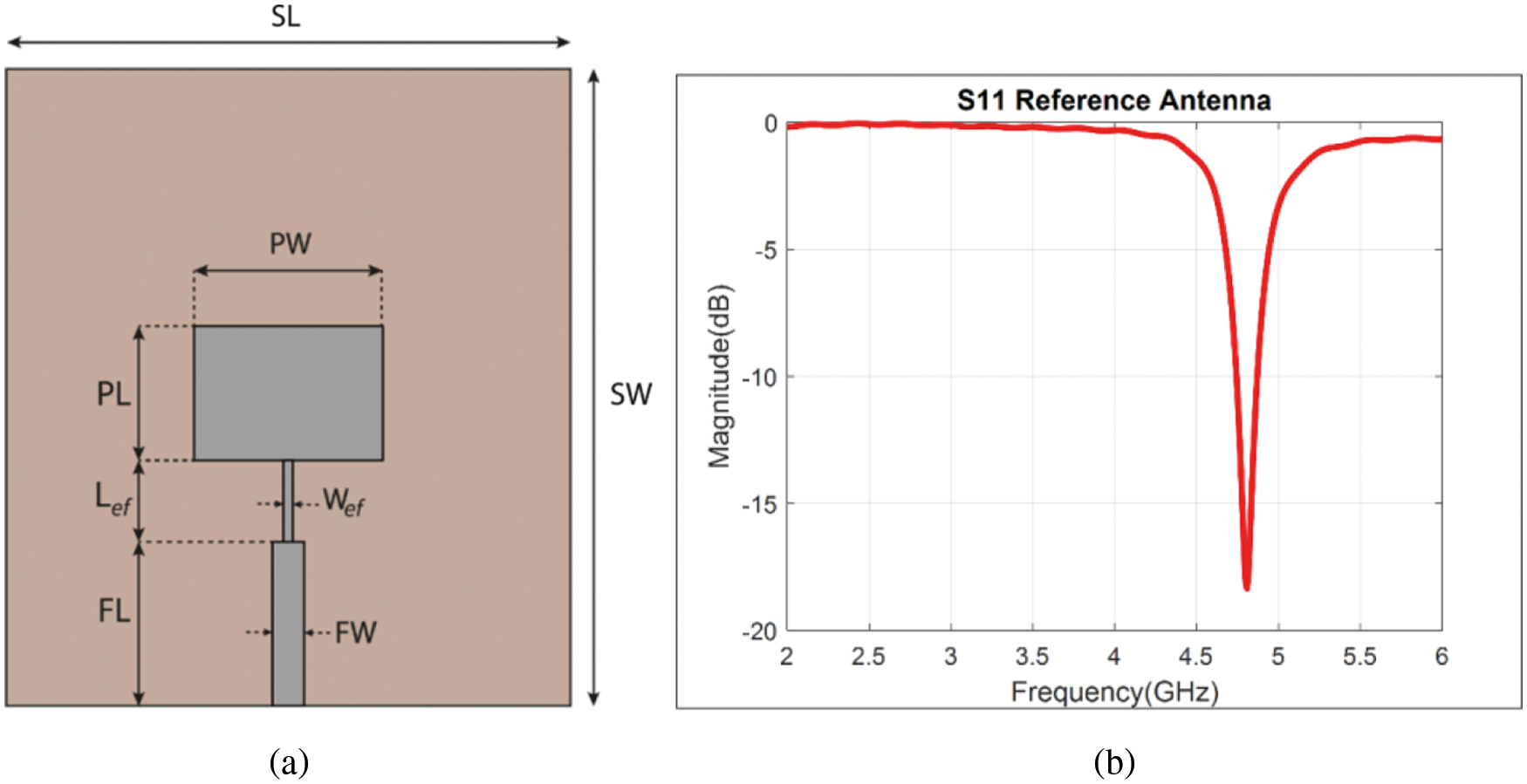
Figure 1: Source MPA (a) Top View: The optimized parameters are SL = 75 mm, SW = 60 mm, PL = 15 mm, PW = 20.5 mm, FL = 18 mm, FW = 3.5 mm, Lef = 12 mm, Wef = 0.5 mm, (b) Simulated S-Parameter
In this section, the design of the novel MTM structure is presented. The MTM is a window-shaped periodic structure having a four-fold symmetry which makes it a polarization-independent MTM. The MTM unit cell is designed on 0.4 mm thick Roger RO4003C substrate with dielectric constant 3.55 and loss tangent 0.0027. Fig. 2a illustrates the geometry of the proposed MTM unit cell. The periodicity of the unit cell is p = 5 mm. The periodic boundary conditions are applied to the unit cell as shown in Fig. 2b. The unit cell is simulated in Computer Simulation Technology (CST) Microwave Studio [27]. The effective parameters of the MTM are extracted using Smith's parameter extraction method [28].
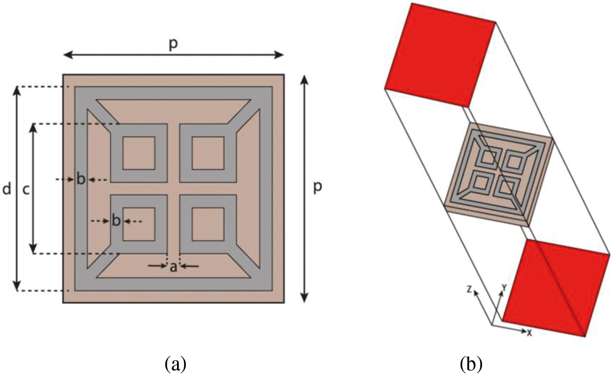
Figure 2: MTM unit cell (a) Top view, The dimensions are p = 5 mm, a = 0.3 mm, b = 0.2 mm, c = 1.7 mm, d = 4.68 mm. (b) 3D view
The effective permittivity (εr) and permeability (μr) of the MTM are plotted in Fig. 3. The effective permittivity is observed to be very low around 4.8 GHz, whereas the effective permeability is very high. Thus, the MTM is acting as an Epsilon-Near-Zero (ENZ)-Mu-Very-Large (MVL) MTM around 4.8 GHz. As a result, this MTM responds heavily to the incident magnetic field and negligibly to the incident electric field, so the MTM is a magnetic field coupled structure. This is validated by strong magnetic field distribution and comparatively weak electric field distribution on MTM unit cell shown in Fig. 4.
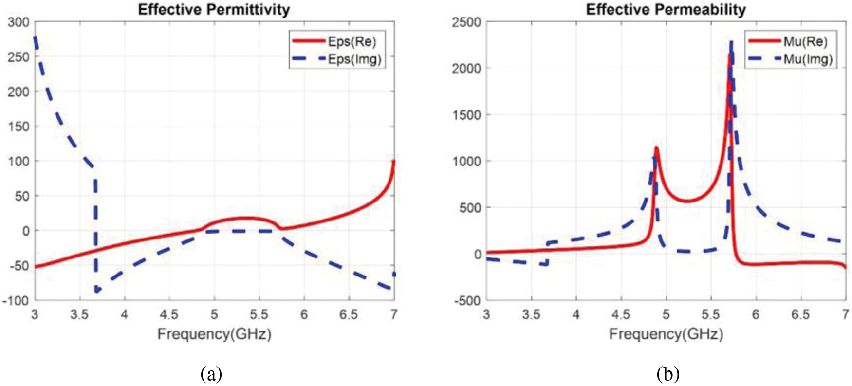
Figure 3: Effective parameters of the proposed MTM unit cell (a) Permittivity (b) Permeability
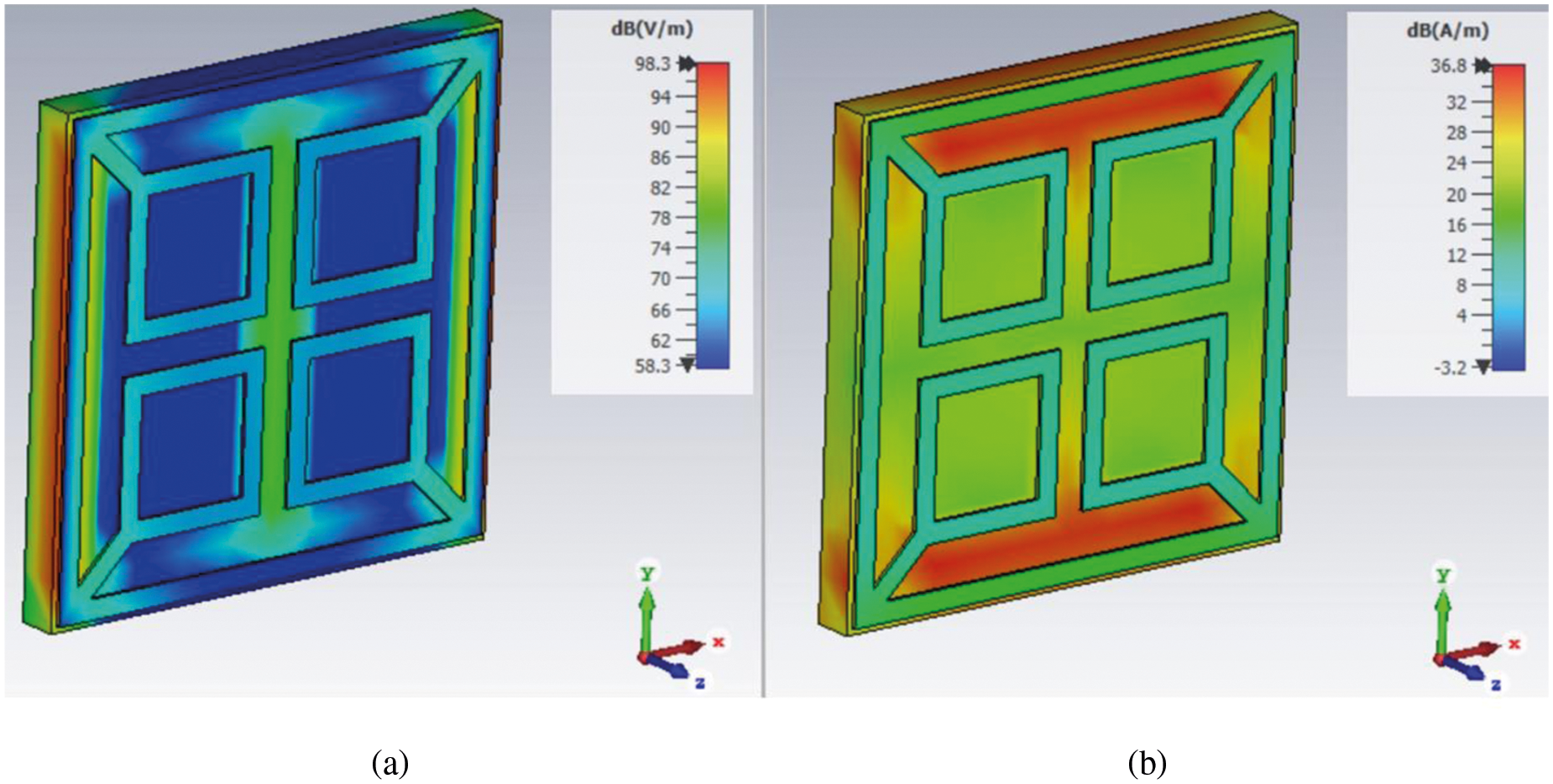
Figure 4: Field distribution on proposed MTM unit cell at 4.8 GHz (a) E-field (b) H-field
4 Proposed Antenna with Novel MTM Superstrate
Fig. 5 shows the structure of the proposed antenna with a novel MTM superstrate. The MTM slab is placed at the height (hgt) of 13 mm, i.e., 0.208λ0, from the source antenna. The simulation results show that an array of 4 × 4 MTM unit cells placed over the MPA acts efficiently and improves the antenna gain significantly. Thus, an array of 4 × 4 MTM unit cells is employed as superstrate above the source antenna to increase the antenna gain.
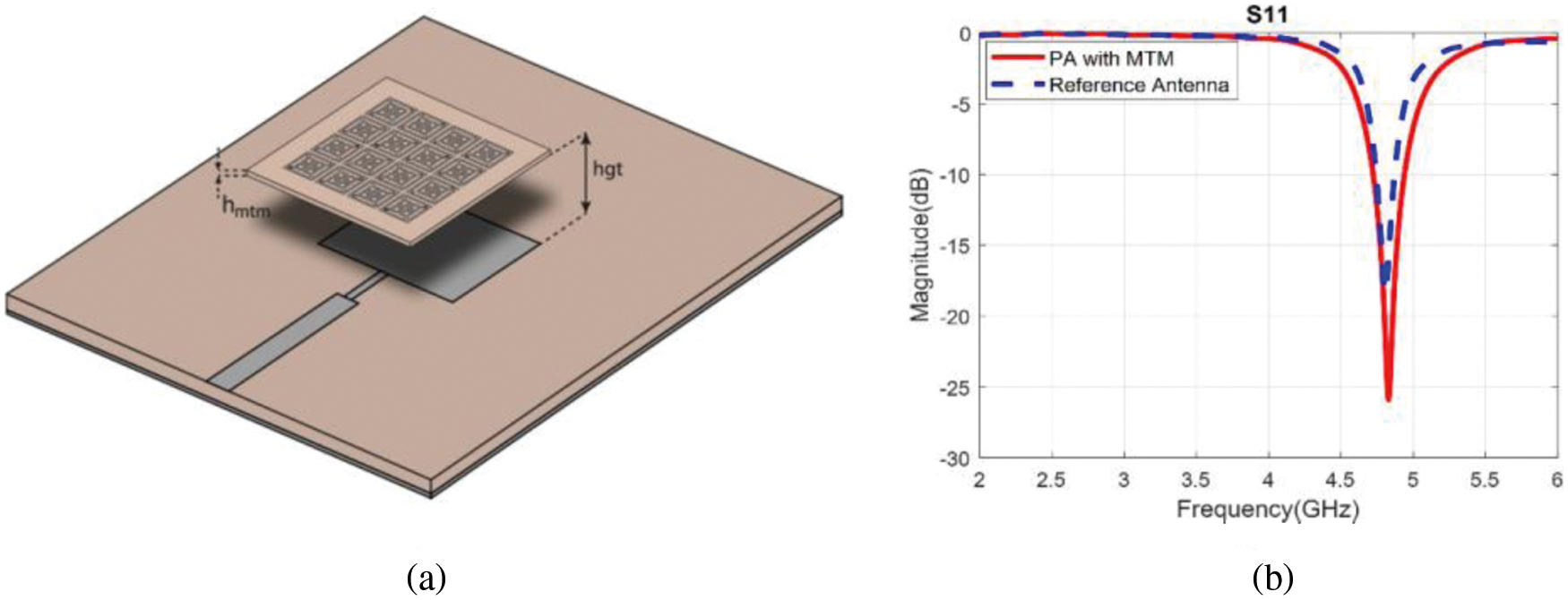
Figure 5: (a) Proposed antenna with 4 × 4 MTM superstrate; hmtm = 0.4 mm, hgt = 13 mm (b) Simulated S11 for the Proposed Antenna
Fig. 5b shows the simulated S11 plot for the proposed antenna. The operational bandwidth of the antenna improves after the placement of the MTM superstrate. The effective bandwidth for the proposed antenna design is observed to be 0.21 GHz i.e., from 4.72 GHz to 4.93 GHz. The simulated gain variations against theta and frequency are plotted in Figs. 6a and 6b respectively. A significant amount of gain enhancement is observed for the proposed antenna i.e., after placement of MTM superstrate the antenna achieves a peak gain of 7.68 dBi. Thus, a gain enhancement of 2.22 dBi was achieved.
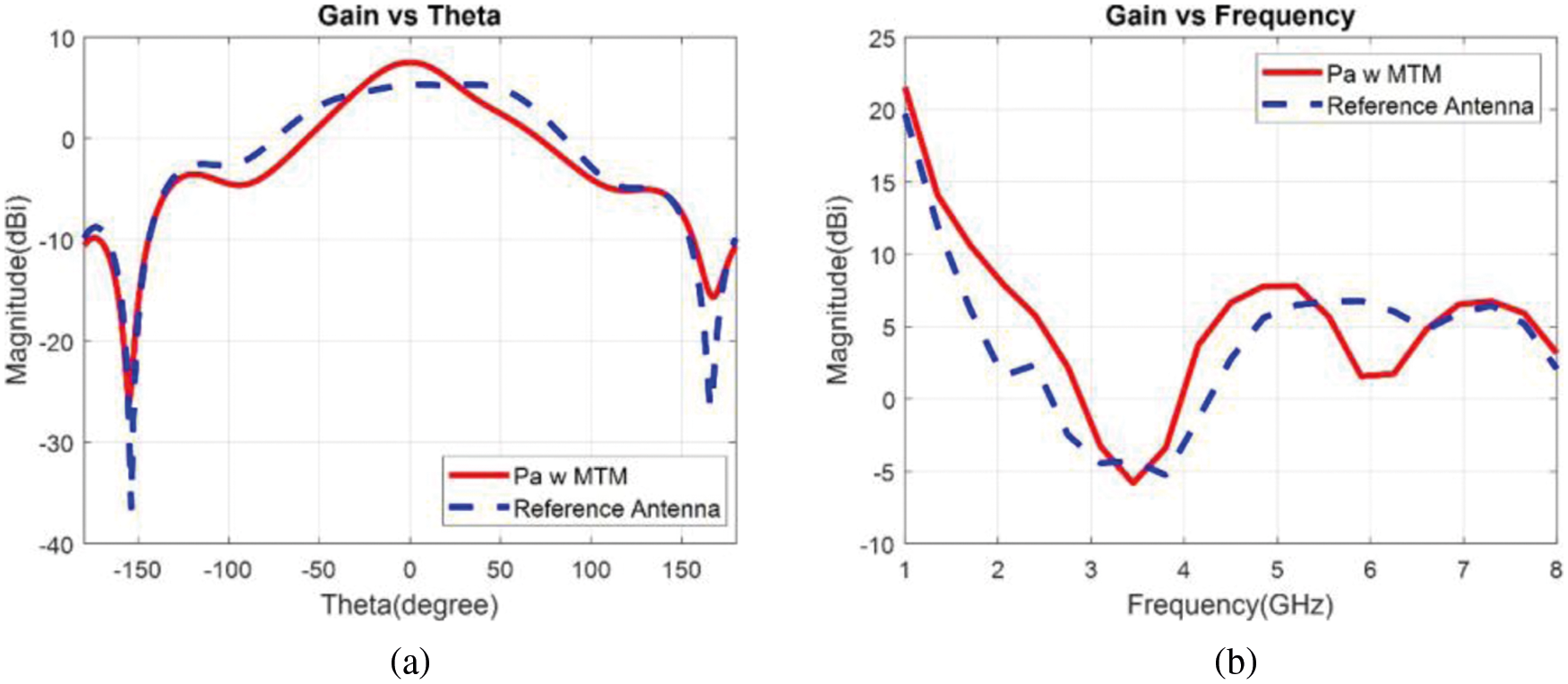
Figure 6: Simulated gain for proposed antenna (a) vs. Theta (b) vs. frequency
Fig. 7 shows the simulated radiation patterns of the proposed antenna for XZ-plane and YZ-plane. For the XZ-plane at 4.8 GHz, the antenna has an HPBW of 80.30 with side lobe level −17.6 dB and main lobe direction at 00. Whereas for the YZ-plane at 4.8 GHz the antenna has an HPBW of 61.70 with side lobe level −11.1 dB and main lobe direction at 00. Thus, for the XZ-plane the HPBW of the proposed antenna is reduced from 86.70 to 80.30 (6.40 reduction) and the side-lobe level is reduced by 2.4 dB. Similarly, in YZ-plane the HPBW is reduced to half i.e., from 130.80 to 61.70 (11.90 reduction), and the side-lobe level is reduced by 3.2 dB. This shows that the MTM superstrate is acting as a lens and focusing the electromagnetic beam.
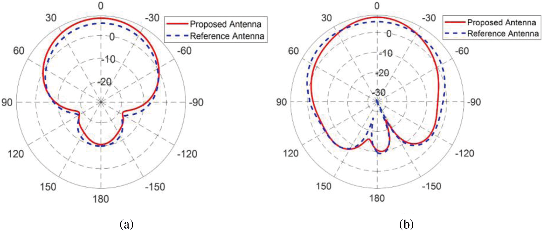
Figure 7: Radiation pattern of proposed antenna with 4 × 4 MTM superstrate at 4.8 GHz (a) XZ-plane (b) YZ-plane
To validate the proposed antenna design, the 4 × 4 MTM slab and the MPA were fabricated and analyzed in anechoic chamber and radiation patterns in E-plane and H-plane were measured. Fig. 8a shows the fabricated prototype of the proposed antenna while Fig. 8b shows its measurement setup in anechoic chamber. The S11 parameter of the fabricated prototype was measured using Agilent E8362 VNA and is plotted in Fig. 9. The measure S11 results match well with the simulation results i.e., after the placement of MTM superstrate the impedance bandwidth improves.
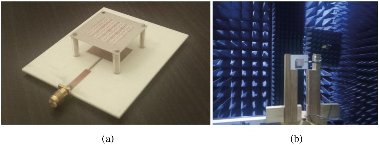
Figure 8: (a) Fabricated prototype of antenna with MTM superstrate (b) Measurement setup for radiation patterns
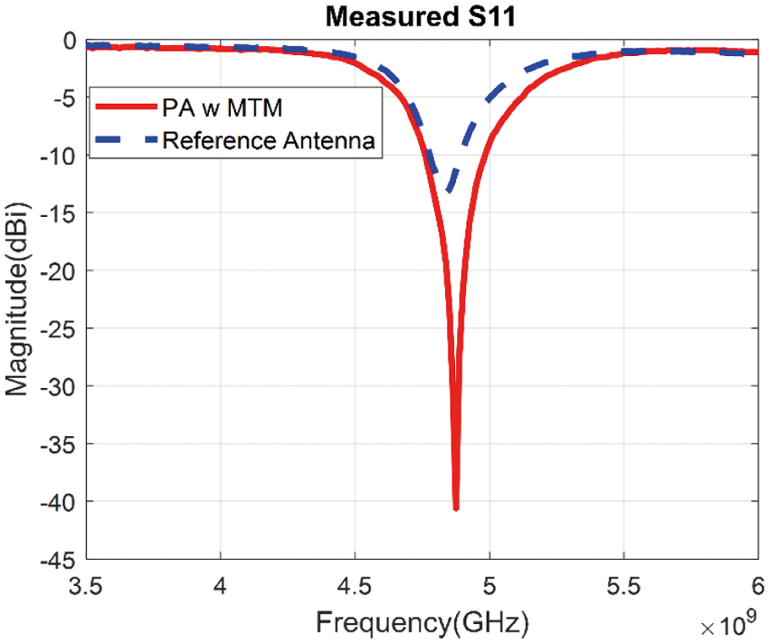
Figure 9: Measured S-parameters for source and proposed antenna
The radiation patterns in E-plane and H-plane for the fabricated prototype are shown in Fig. 10. It is evident that the gain of the antenna increases after the placement of MTM superstrate. The gain after the placement of MTM superstrate is measured to be 7.63 dBi which is 2.42 dBi higher than that of the source MPA. A slight difference is observed between simulated, and measurement results due to practical conditions and measurement errors.
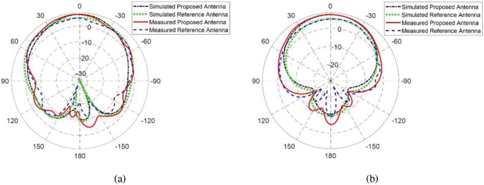
Figure 10: Simulated and measured radiation patterns for proposed antenna and source antenna at 4.8 GHz (RA). (a) XZ or H-plane. (B) YZ or E-plane
To validate the four-fold polarization independence of proposed metasurface, the unit cell is simulated with Floquet ports for both TE and TM modes. The transmission response is given in Fig. 11. It can be observed that for different polarization angles the transmission response of proposed structure is uniform for both TE and TM modes.
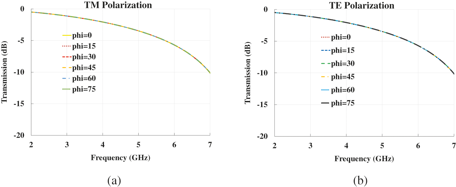
Figure 11: Transmission response of proposed meta surface for (a) TM polarization (b) TE polarization
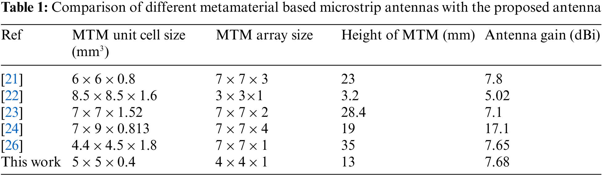
Tab. 1 compares the antenna gain of different metamaterial based microstrip antennas with the gain of the proposed antenna. it is evident that the proposed antenna with metamaterial is more compact and low profile as compared to the previous reported work. The proposed antenna achieves a gain of 7.68 dBi with compact and less number of MTM unit cells with a profile of 13 mm.
In this paper, a novel MTM design for the gain enhancement of a sub-6 GHz microstrip antenna resonating at 4.8 GHz is proposed. The MTM unit cell has a fourfold symmetry which makes it a polarization independent MTM. The MTM is acting as an Epsilon-Near-Zero (ENZ)-Mu-Very-Large (MVZ) MTM around 4.8 GHz. A 4 × 4 array of MTM unit cells is imposed as a superstrate on the source MPA. Using MTM superstrate, the gain of the source antenna is enhanced by 2.38 dBi. The measurement results match well with simulation results. The resonance frequency of the antenna lies in the sub-6 GHz band so the proposed antenna design can be used for 5G applications.
Funding Statement: This project was funded by the Deanship of Scientific Research (DSR), King Abdulaziz University, Jeddah, Saudi Arabia under Grant No. (KEP-PhD-13-135-42). The authors, therefore, acknowledge with thanks DSR technical and financial support.
Conflicts of Interest: The authors declare that they have no conflicts of interest to report regarding the present study.
1. A. Iqbal, A. Smida, A. J. Alazemi, M. I. Waly, N. K. Mallat et al., “Wideband circularly polarized MIMO antenna for high data wearable biotelemetric devices,” IEEE Access, vol. 8, no. 2020, pp. 17935–17944, 2020. [Google Scholar]
2. C. A. Balanis, “Antenna theory: A review,” in Proc. of the IEEE, vol. 80, no. 1, pp. 7–23, 1992. [Google Scholar]
3. S. B. Yeap and Z. N. Chen, “Microstrip patch antennas with enhanced gain by partial substrate removal,” IEEE Transactions on Antennas and Propagation, vol. 58, no. 9, pp. 2811–2816, 2010. [Google Scholar]
4. J. S. Kuo and G. B. Hsieh, “Gain enhancement of a circularly polarized equilateral-triangular microstrip antenna with a slotted ground plane,” IEEE Transactions on Antennas and Propagation, vol. 51, no. 7, pp. 1652–1656, 2003. [Google Scholar]
5. S. Zhu, H. Liu, P. Wen and Z. Chen, “A compact gain-enhanced Vivaldi antenna array with suppressed mutual coupling for 5G mmwave application,” IEEE Antennas and Propagation Letters, vol. 17, no. 5, pp. 776–779, 2018. [Google Scholar]
6. N. Hussain, H. H. Tran and T. T. Le, “Single-layer wideband high-gain circularly polarized patch antenna with parasitic elements,” AEU-International Journal of Electronics and Communications, vol. 113, pp. 152992, 2020. [Google Scholar]
7. C. E. Santosa and J. T. Sri Sumantyo, “Gain enhancement of C band linearly-polarized microstrip antenna with square parasitic patch for airborne LP-SAR sensor,” in Progress in Electromagnetics Research Symposium, Toyama, Japan, pp. 858–863, 2018. [Google Scholar]
8. Q. X. Chu, X. R. Li and M. Ye, “High-gain printed Log-Periodic dipole array antenna with parasitic cell for 5G communication,” IEEE Transactions on Antennas and Propagation, vol. 65, no. 12, pp. 6338–6344, 2017. [Google Scholar]
9. Z. J. Han, W. Song and X. Q. Sheng, “Gain enhancement and RCS reduction for patch antenna by using polarization-dependent EBG surface,” IEEE Antennas and Wireless Propagation Letters, vol. 16, pp. 1631–1634, 2017. [Google Scholar]
10. Y. Alnaiemy and L. Nagy, “Improved antenna gain and efficiency using novel EBG layer,” in IEEE 15th Int. Conf. of System of Systems Engieering (SoSE), Budapest, Hungary, pp. 271–276, 2020. [Google Scholar]
11. Y. Alnaiemy, T. A. Elwi and N. Lajos, “Enhancing the microstrip antenna gain using a novel EBG lens based on a single layer,” in 11th Int. Symposium on Communication Systems, Networks & Digital Signal Processing (CSNDSP), Budapest, Hungary, pp. 1–4, 2018. [Google Scholar]
12. R. V. Sravya and R. Kumari, “Gain enhancement of patch antenna using L-slotted mushroom EBG,” in Conf. on Signal Processing and Communication Engineering Systems (SPACES), Vijayawada, India, pp. 37–40, 2018. [Google Scholar]
13. P. Prakash, M. P. Abegaonkar, A. Basu and S. K. Koul, “Gain enhancement of a CPW-Fed monopole antenna using polarization-insensitive AMC structure,” IEEE Antennas and Wireless Propagation Letters, vol. 12, pp. 1315–1318, 2013. [Google Scholar]
14. W. Yang, W. Che and H. Wang, “High-gain design of a patch antenna using stub-loaded artificial magnetic conductor,” IEEE Antennas and Wireless Propagation Letters, vol. 12, pp. 1172–1175, 2013. [Google Scholar]
15. S. Pandit and P. Ray, “Metamaterial-inspired low-profile high-gain slot antenna,” Microwave and Optical Technology Letters, vol. 61, no. 9, pp. 2068–2073, 2019. [Google Scholar]
16. J. P. Turpin, Q. Wu, D. H. Werner, B. Martin, M. Bray et al., “Low cost and broadband dual-polarization metamaterial lens for directivity enhancement,” IEEE Transactions on Antennas and Propagation, vol. 60, no. 12, pp. 5717–5726, 2012. [Google Scholar]
17. Z. H. Jiang, Q. Wu, D. E. Brocker, P. E. Sieber and D. H. Werner, “A Low-profile high-gain substrate-integrated waveguide slot antenna enabled by an ultrathin anisotropic zero-index metamaterial coating,” IEEE Transactions on Antennas and Propagation, vol. 62, no. 3, pp. 1173–1184, 2014. [Google Scholar]
18. S. Pandit, A. Mohan and P. Ray, “A Low-profile high-gain substrate-integrated waveguide-slot antenna with suppressed cross polarization using Metamaterial,” IEEE Antennas and Wireless Propagation Letters, vol. 16, pp. 1614–1617, 2017. [Google Scholar]
19. B. Yuan, Y. H. Zheng, X. H. Zhang, B. You and G. Q. Luo, “A bandwidth and gain enhancement for microstrip antenna based on metamaterial,” Microwave and Optical Technology Letters, vol. 59, no. 12, pp. 3088–3093, 2017. [Google Scholar]
20. Z. Liu, P. Wang and Z. Zeng, “Enhancement of the gain for microstrip antennas using negative permeability Metamaterial on low temperature co-fired ceramic (LTCC) substrate,” IEEE Antennas and Wireless Propagation Letters, vol. 12, pp. 429–432, 2013. [Google Scholar]
21. D. Li, Z. Szabó, X. Qing, E. Li and Z. N. Chen, “A high gain antenna with an optimized Metamaterial inspired superstrate,” IEEE Transactions on Antennas and Propagation, vol. 60, no. 12, pp. 6018–6023, 2012. [Google Scholar]
22. S. Roy and U. Chakraborty, “Gain enhancement of a dual-band WLAN microstrip antenna loaded with diagonal pattern metamaterials,” IET Communications, vol. 12, no. 12, pp. 1448–1453, 2018. [Google Scholar]
23. A. Bakhtiari, “Investigation of enhanced gain miniaturized patch antenna using near zero index metamaterial structure characteristics,” IETE Journal of Research, vol. 65, pp. 1–8, 2019. [Google Scholar]
24. O. Borazjani, M. Naser-Moghadasi, J. Rashed-Mohassel and R. Sadeghzadeh, “Design and fabrication of a new high gain multilayer negative refractive index metamaterial antenna for X-band applications,” International Journal of RF and Microwave Computer-Aided Engineering, vol. 30, no. 9, pp. e22284, 2020. [Google Scholar]
25. D. Samantaray and S. Bhattacharyya, “A Gain-enhanced slotted patch antenna using metasurface as superstrate configuration,” IEEE Transactions on Antennas and Propagation, vol. 68, no. 9, pp. 6548–6556, 2020. [Google Scholar]
26. H. Suthar, D. Sarkar, K. Saurav and K. V. Srivastava, “Gain enhancement of microstrip patch antenna using near-zero index metamaterial (NZIM) lens,” in Twenty First National Conf. on Communications (NCC), Mumbai, India, pp. 1–6, 2015. [Google Scholar]
27. C. S. T. Studio Suite, “CST microwave studio,” 2020. http://www.cst.com. [Google Scholar]
28. D. R. Smith, D. C. Vier, T. Koschny and C. M. Soukoulis, “Electromagnetic parameter retrieval from inhomogeneous metamaterials,” Physical Review E, vol. 71, no. 3, pp. 036617, 2005. [Google Scholar]
 | This work is licensed under a Creative Commons Attribution 4.0 International License, which permits unrestricted use, distribution, and reproduction in any medium, provided the original work is properly cited. |