DOI:10.32604/cmc.2022.025650
| Computers, Materials & Continua DOI:10.32604/cmc.2022.025650 | |
| Article |
Linearly Polarized Millimeter Wave Reflectarray with Mutual Coupling Optimization
1Centre for Telecommunication Research & Innovation (CETRI), Faculty of Electrical and Electronic Engineering Technology, Universiti Teknikal Malaysia Melaka (UTeM), Melaka, 76100, Malaysia
2Dawood University of Engineering and Technology Karachi City, Sindh, 74800, Pakistan
3Faculty of Electrical and Electronic Engineering, Universiti Tun Hussein Onn Malaysia, Batu Pahat, 86400, Johor, Malaysia
4Wireless Communication Centre, Universiti Teknologi Malaysia, Johor Bahru, 81301, Malaysia
5Faculty of Computing and Engineering, Quest International University, Ipoh, 30250, Perak, Malaysia
6Balochistan University of Information Technology (FICT), Engineering and Management Sciences, Quetta, Pakistan
7Electrical Engineering Department, College of Engineering, Imam Mohammad Ibn Saud Islamic University, Riyadh, Saudi Arabia
*Corresponding Author: Z. A. Shamsan. Email: zashamsan@imamu.edu.sa
Received: 30 November 2021; Accepted: 17 January 2022
Abstract: This work provides the design and analysis of a single layer, linearly polarized millimeter wave reflectarray antenna with mutual coupling optimization. Detailed analysis was carried out at 26 GHz design frequency using the simulations of the reflectarray unit cells as well as the periodic reflectarray antenna. The simulated results were verified by the scattering parameter and far-field measurements of the unit cell and periodic arrays, respectively. A close agreement between the simulated and measured results was observed in all the cases. Apart from the unit cells and reflectarray, the waveguide and horn antenna were also fabricated to be used in the measurements. The measured scattering parameter results of the proposed circular ring unit cells provided a maximum reflection loss of 2.8 dB with phase errors below 10°. On the other hand, the measured far-field results of the 20 × 20 reflectarray antenna provided a maximum gain of 26.45 dB with a maximum 3 dB beam width of 12° and 1 dB gain drop bandwidth of 13.1%. The performance demonstrated by the proposed reflectarray antenna makes it a potential candidate to be used in modern-day applications such as 5th Generation (5G) and 6th Generation (6G) communication systems.
Keywords: Reflectarray; millimeter wave antenna; mutual coupling; antenna measurements
Printed reflectarray as introduced by Berry in 1963 [1] is a planar reflector antenna consisting of an array of printed microstrip patch elements on a dielectric substrate and is fed by a horn antenna. By the time of the invention of reflectarray, it was considered as a potential alternative to the high gain parabolic reflectors and phased array antenna. However, unlike parabolic reflectors, the reflectarray antenna exhibits a flat, low cost and lightweight reflecting surface. On the other hand, contrary to the phased array antennas, the reflectarray does not require the integration of complex electronic circuitry for controlling the phase of its elements.
In modern days, the reflectarray antenna has developed to such an extent that it is considered suitable for applications such as in 5G and 6G communication systems [2–6]. Recently, researchers have also investigated the possibilities of using the reflectarray antennas in other advanced applications such as snow mass measurements [7], In-band full-duplex applications [8], near meta steering systems [9] and other high power microwave applications [10]. All these applications need the reflectarray antenna to provide optimum performance in terms of losses, phase distribution, mutual coupling, polarization, gain, beamwidth and other performance parameters.
In its basic form, a reflectarray is a high gain passive antenna, where the phase of individual elements controlled by their geometrical dimensions drives the overall phase performance. While in advanced forms, reflectarrays can be used for beam steering by different methods such as the integration of Radio Frequency Micro Electromechanical Systems (RF MEMS) as switches [11–14], use of diodes for frequency variations and beam steering [15–19], use of liquid crystals for phase and frequency variation [20–22] and mechanical rotation of the antenna for beam steering [23–25]. All these techniques have their own advantages and can be used for designing the reflectarray antennas deployable in modern-day applications. However, the basic reflectarray design needs to be optimized in all the cases in order to avoid extra losses caused by the design configurations and other integrated elements.
This work provides a detailed step by step guideline on designing the reflectarray antenna with optimized performance. Simulation techniques of unit cells have been explained and the results are verified by the scattering parameter measurements. Moreover, periodic reflectarrays have also been designed and verified by the far-field measurements. The important considerations during the design and analysis procedure have been highlighted in this work. Fig. 1 provides a graphical summary of the presented work. The proposed reflectarray has been designed in two phases as shown in Fig. 1. In phase 1, the reflectarray unit cell design and analysis were carried out with scattering parameter measurements and is explained in detail in Section 2 of this paper. Phase 2 covers the design, fabrication, and far-field measurements of the proposed reflectarray as presented in Sections 3 and 4 of this work.
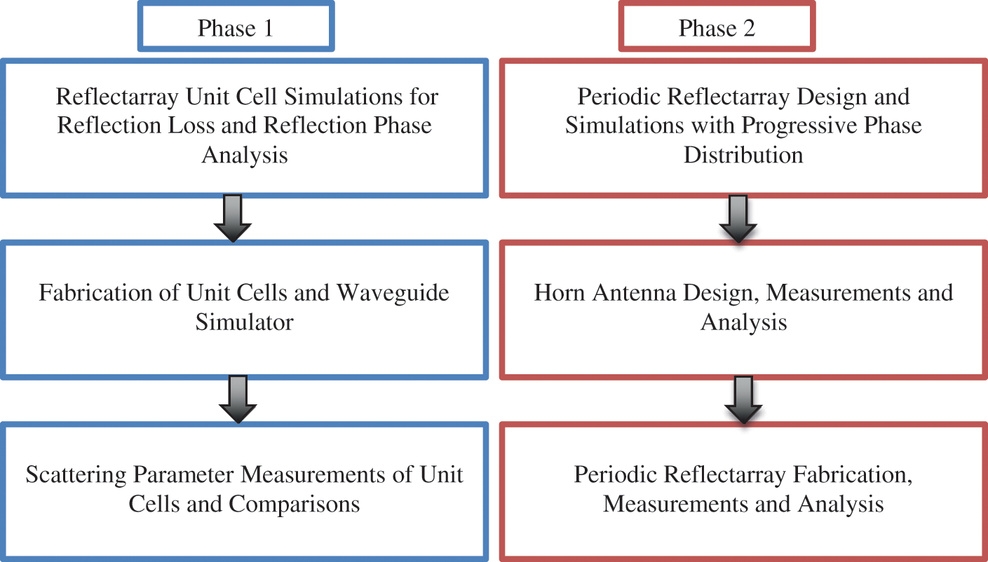
Figure 1: Graphical flow of the proposed reflectarray design
2 Reflectarray Unit Cell Design and Analysis
In order to perform a detailed analysis on the reflectarray performance, unit cell elements have been designed using circular ring configuration within the frequency range of 24 to 28 GHz. 3D-EM simulations and scattering parameter measurements have been carried out in order to verify the results. The design procedure and comparative results are explained in the following sections.
The unit cell can be mirrored as an infinite array by using proper boundary conditions, which helps to predict the behaviour of a large reflectarray antenna. In this work, the commercially available computer models of Computer Simulation Technology (CST) and High Frequency Simulation Simulator (HFSS) were used to perform this analysis. E-Walls and H-walls were implemented in CST MWS with Waveguide port while Master and Slave boundary conditions were used in HFSS with Floquet port excitation. The two computer models are based on different analysis techniques and hence help validate the proposed design configuration. Fig. 2a shows the proposed reflectarray unit cell configuration. The basic element was designed to resonate at 26 GHz with an external ring diameter of 1.61 mm. The substrate used for this design was Rogers RT/duroid 5880 with 0.508 mm thickness. The length and width of the substrate were kept at λ/2 × λ/2 (5.77 mm × 5.77 mm), which provides a half wavelength interelement spacing. This interelement spacing helps to optimize the mutual coupling between the neighboring elements. Another factor that causes the mutual coupling in the conventional reflectarray antennas design is the element to element spacing, which varies significantly if rectangular patch elements are used. However, because of the symmetricity of the proposed design, the variation in the element to element spacing can be minimized and hence mutual coupling can be optimized. Fig. 2b shows the surface current distribution on the resonant circular ring element. The maximum surface currents were observed to be in the middle of the ring because the E-fields were excited in the Y-axis direction.
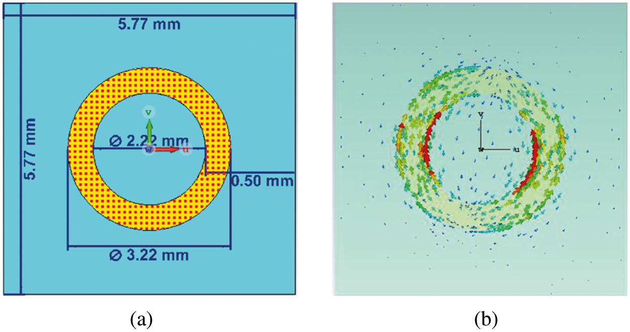
Figure 2: Unit cell reflectarray design (a) Proposed design configuration (b) Surface current distribution
After the design of the basic resonant element, the radius of the circular ring was varied from 1.51 to 1.71 mm. This variation provided a frequency sweep in the desired frequency range (24–28 GHz). Hence, the reflection loss and reflection phase curves can be obtained against the variation in the element radius, as shown in Fig. 3. It can be observed from Fig. 3 that the maximum reflection loss was observed to be 2.8 dB while the reflection phase curve provides a very fine progressive phase distribution. Moreover, the phase errors were observed to be less than 10°, which are acceptable for the single-layer reflectarray design.
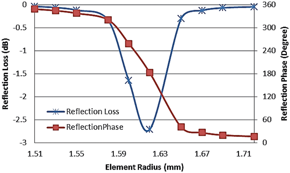
Figure 3: Reflection loss and reflection phase curves for unit cells
The proposed reflectarray unit cells with different radii of the ring elements were also fabricated using Rogers RT/duroid 5880 in a two-element configuration. This configuration is useful for considering the mutual coupling effects due to the neighbouring element. The maximum dimensions of the fabricated two-element unit cell were λ × λ/2 at the center frequency of 26 GHz as shown in Fig. 4.

Figure 4: The fabricated two-element reflectarray unit cell
A waveguide simulator was also designed and fabricated for the scattering parameter measurements of the proposed reflectarray unit cells. The scattering behaviour of infinite reflectarray can be analyzed using the waveguide simulator technique exactly in the same manner as depicted in the 3D-EM simulators using infinite boundary conditions. Fig. 5a shows the schematic of the designed waveguide simulator with detailed dimensions. The backside of the waveguide simulator had to follow the standard WR-34 coaxial to waveguide adapter, which can be used for the frequency range of 22 to 33 GHz. On the other hand, the front side followed the dimensions of the fabricated two-element reflectarray unit cells. Therefore, the internal hollow cavity of the designed waveguide was tapered in both X and Y directions. However, this tapering can affect the incident angle of the impinged E-fields and hence can alter the reflection phase of the reflectarray unit cells. In order to avoid this unwanted phase alteration, the length of the waveguide simulator was extended up to 10λ, reducing the tapered angle to 0.71° and 0.34° in the X and Y directions, respectively. The analysis based on simulations proved that with these angles, the reflection properties of the unit cells were not affected. Fig. 5b shows the hollow waveguide fabricated using wire cutting on an Aluminum brick.

Figure 5: Designed waveguide simulator (a) Schematic (b) Fabricated
2.3 Scattering Parameter Measurements
Scattering parameter measurements of the fabricated reflectarray unit cells were carried out using the designed waveguide, as shown in Fig. 6. The coaxial cable from the vector network analyzer was connected to the waveguide backside through a WR-34 coaxial to waveguide adapter while the fabricated unit cells were inserted at the front of the waveguide. Extra space of 1 mm was kept at the front side of the waveguide so that the unit cells could be held properly.

Figure 6: Scattering parameter measurements setup of reflectarray unit cells
Fig. 7 shows the comparison between measured and simulated scattering parameter results of the fabricated reflectarray unit cell resonating at 26 GHz. A close agreement between the measured and simulated reflection results can be observed from Fig. 7, especially in terms of the resonant frequency. The measured reflection loss was observed to be slightly higher as compared to the simulations, which was expected due to the extra losses incurred during measurements by the connections and cables. Furthermore, away from the resonance, some extra ripples were also observed, which could also be due to the measurement setup and connections. The measured reflection phase also followed a similar trend with some ripples, but the overall phase was in very good agreement.

Figure 7: Comparison between measured and simulated scattering parameters
Different reflectarray unit cells were fabricated with radius varying from 1.51 to 1.71 mm and scattering parameter measurements were carried out for all the fabricated unit cells. Fig. 8 shows a comparison between the measured and simulated results for element radius vs. scattering parameters. It can be observed that the measured results for all the fabricated unit cells provided a close agreement with the simulated results of CST MWS and HFSS. Some discrepancies were observed in these measurements, which can also be due to the same reasons as explained earlier. Moreover, the reflection phase results provided the progressive phase distribution which is required for the periodic reflectarray design.

Figure 8: Comparison between measured and simulated scattering parameters for different radii unit cells
3 Periodic Reflectarray Antenna Design and Analysis
After finalizing the unit cell design and analysis, a 20 × 20 periodic reflectarray was designed and fabricated for the far-field measurements. This section explains the design, simulations, fabrications and measurements of the proposed reflectarray.
The simulations and analysis of the proposed periodic reflectarray were carried out using CST MWS. The interelement spacing for the array design was kept at half-wavelength, while the phase distribution was implemented using a specially designed mathematical model. The mathematical model was designed in such a way so that the proposed unit cells can be placed in the array environment with progressive phase distribution. The element used for the reflectarray design were the circular rings with radius varying from 1.51 to 1.71 mm printed on Rogers RT/duroid 5880 dielectric substrate. A standard horn with 10 dB gain was used to feed the reflectarray at a distance specified by the f/D ratio. Fig. 9 shows the simulated model of the proposed periodic reflectarray antenna while Fig. 10 provides the simulated far-field radiation pattern of the proposed reflectarray. In order to avoid the blockage from the feed horn, the array was designed to be placed with a 20° tilt in the XY-plane. This 20° provided a reflection of the main beam towards 40° in the azimuth plane. A 10° tilt was also implemented for the simulations of the periodic reflectarray. However, it was observed that due to the reflection phase originally adjusted for 20° tilt of array, the 10° tilt provided very high sidelobes and a distorted main beam. On the other hand, the 20° tilt provided a maximum gain of 26.4 dB with side lobes well below the 20 dB level from the main beam.

Figure 9: Simulated model of the proposed reflectarray in CST MWS

Figure 10: Simulated far field radiation pattern of the proposed 20 × 20 periodic reflectarray
The f/D ratio optimization was also carried out in order to achieve the optimized far-field radiation patterns. Fig. 11 shows the results of the gain and the 3 dB angular width obtained by varying the f/D ratio. It can be observed from the results that for 26 GHz, the f/D ratio of 1 provided the desired maximum gain and minimum 3 dB angular width. Hence this f/D ratio of 1 was selected for the final design and further analysis. The proposed 20 × 20 periodic reflectarray was also fabricated using Rogers RT/duroid 5880, as shown in Fig. 12. The reflectarray elements in the fabricated array have a different radius, as explained above. The variation in the radius is only 0.2 mm (1.51 to 1.71 mm); therefore, it is not easily visible to the naked eye. However, this slight variation provided the required progressive phase and also helped in the mutual coupling optimization as explained in Section 1.

Figure 11: Optimization of the f/D ratio for the periodic reflectarray design

Figure 12: The fabricated 20 × 20 circular ring periodic reflectarray
The feed horn plays an important role in the design and analysis of the reflectarray antenna. It can negatively affect the performance of the reflectarray if not designed properly. Therefore, in this work instead of using a standard horn antenna, a custom-made horn antenna has been designed to be used as a feed. The designed antenna dimensions are chosen in such a way that it can provide a 10 dB gain in the frequency range of 24–28 GHz as shown in Fig. 13. The designed horn was fabricated using an Aluminum brick, and its loss performance was measured with the help of a WR-34 coaxial to waveguide adapter in the frequency range between 24 to 28 GHz. Fig. 14 shows the fabricated horn antenna and its loss performance. The resonance behavior of the pyramidal horn can be observed form the return loss performance, where it is observed to be below −10 dB level through the measured range. This shows that the antenna can be used for 24–28 GHz. On the other hand, feed loss is associated with the loss of energy inside the pyramidal horn during its operation. Due to the very low loss performance of the pyramidal horn, feed losses in the reflectarray operation are often neglected. The radiation pattern measurements of the designed horn antenna were also carried out. Fig. 15 shows the comparison between the simulated and measured far-field radiation patterns of the horn antenna. It can be observed from Fig. 15a that the simulated and measured results are in close agreements. Moreover, the cross polarization level are satisfactorily far from the main lobe at the measured 26 GHz frequency. The gain of the designed horn antenna is observed to be between 10 and 12 dB as shown in Fig. 15b.

Figure 13: The schematic of the designed 10 dB horn antenna (A = 15.68, B = 11.36, L = 35, a = 8.63 b = 4.31)

Figure 14: Fabricated horn antenna and its measured loss performance

Figure 15: The simulated and measured radiation characteristics of the pyramidal horn antenna (a) E-plane radiation pattern with measured cross-polarization at 26 GHz (b) Gain vs. frequency
4 Radiation Pattern Measurements
The radiation pattern measurements of the designed reflectarray antenna were carried out in the frequency range of 24 to 28 GHz in a 3 meter anechoic chamber. Fig. 16 shows the measurement setup of the proposed reflectarray antenna. A standard probe was used for transmitting at a far-field distance from the reflectarray antenna. Fig. 17 provides the comparison between the simulated and measured far-field radiation pattern results of the designed reflectarray antenna at 26 GHz. The measured results provided a close agreement with the simulated results both in the Azimuth and Elevation planes. A measured maximum gain of 26.45 dB was observed at approximately 40° main beam direction, as predicted by simulations. Although there is a slight discrepancy in terms of the sidelobe levels, the side lobes are still below 20 dB from the main beam, which is good enough for this type of antenna. Moreover, the cross-polarization levels are also below 30 dB as compared to the main beam, in both the Azimuth and Elevation planes. The 3D radiation pattern measured results are shown in Fig. 18 along with Elevation and Azimuth plane curves for the proposed reflectarray antenna. A clear peak in the desired direction of 0° Elevation and 40° Azimuth plane can be observed from the measured results.

Figure 16: Radiation pattern measurement setup of the designed reflectarray antenna

Figure 17: Comparison between simulated and measured far field radiation pattern measurements of the designed reflectarray antenna at 26 GHz

Figure 18: 3D measured radiation pattern and elevation vs. azimuth plane plot for highlighting the beam direction of the proposed reflectarray antenna at 26 GHz
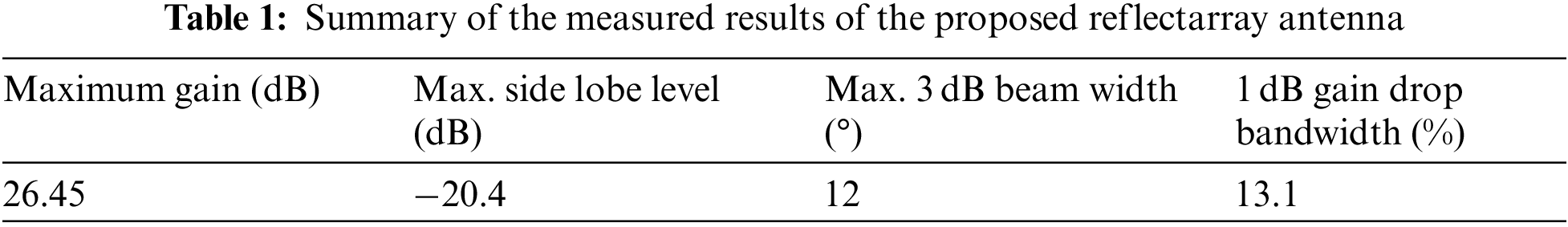
The far-field measurements were also carried out for other frequencies (24–28 GHz) in order to verify the simulated results. Fig. 19 provides the comparisons between the simulated and measured results of the proposed reflectarray antenna in the desired frequency range. It can be observed that, as expected, the maximum gain was achieved at 26 GHz while the overall measured gain varied from 26.45 to 25.38 dB through the investigated frequency range. Tab. 1 summarizes the overall performance of the proposed reflectarray antenna. As depicted in Tab. 1, the maximum 3 dB beamwidth was observed to be 12°, while 1 dB gain drop bandwidth measured by the results in Fig. 19 was observed to be 13.1%. These performances are deemed satisfactory for such type of millimeter wave antenna design.

Figure 19: Comparison between simulated and measured gain vs. frequency curves
A millimeter wave high gain reflectarray antenna design is proposed with mutual coupling optimization. The detailed design steps are explained with the 3D EM simulations of reflectarray unit cells and periodic reflectarray, scattering parameter measurements of unit cells, fabrication of the unit cells and reflectarray, design and fabrication of horn antenna, and far-field measurements of the reflectarray antenna. The explained procedure can be used as a guide for the effective reflectarray antenna design. Moreover, the proposed reflectarray antenna provided satisfactory performance and can be used in modern-day applications such as 5G and 6G communication systems.
Funding Statement: The authors extend their appreciation to the Deanship of Scientific Research at Imam Mohammad Ibn Saud Islamic University for funding this work through Research Group No. RG-21-12-08. The initials of authors who receive the grant are: ZAS. The URL of the sponsor's website: https://units.imamu.edu.sa/deanships/sr/Pages/default.aspx.
Conflicts of Interest: The authors declare that they have no conflicts of interest to report regarding the present study.
1. D. G. Berry, R. G. Malech, and W. A. Kennedy, “The reflectarray antenna,” IEEE Transactions on Antennas and Propagation, vol. 11, no. 6, pp. 645–651, 1963. [Google Scholar]
2. X. Meng, M. Nekovee and D. Wu, “The design and analysis of electronically reconfigurable liquid crystal-based reflectarray metasurface for 6G beamforming, beamsteering, and beamsplitting,” IEEE Access, vol. 9, pp. 155564–155575, 2021. [Google Scholar]
3. M. H. Dahri, M. Inam, M. H. Jamaluddin and M. R. Kamarudin, “A review of high gain and high efficiency reflectarrays for 5G communications,” IEEE Access, vol. 6, no. 1, pp. 5973–5985, 2018. [Google Scholar]
4. M. H. Dahri, M. H. Jamaluddin, M. Khalily, M. Inam, R. Selvaraju et al., “Polarization diversity and adaptive beamsteering for 5G reflectarrays: A review,” IEEE Access, vol. 6, no. 1, pp. 19451–19464, 2018. [Google Scholar]
5. M. H. Dahri, M. H. Jamaluddin, M. Inam and M. R. Kamarudin, “A review of wideband reflectarray antennas for 5G communication systems,” IEEE Access, vol. 5, no. 1, pp. 17803–17815, 2017. [Google Scholar]
6. M. Inam, M. H. Dahri, M. H. Jamaluddin, N. Seman, M. R. Kamarudin et al., “Design and characterization of millimeter wave reflectarrays for 5G communication systems,” International Journal of RF and Microwave Computer Aided Engineering, vol. 29, no. 9, pp. 1–12, 2019. [Google Scholar]
7. É. C. Pelletier, C. M. Lecourt and J. -J. Laurin, “Reflectarray antenna concept for a snow mass measurement sar mission in Ku-band on a nanosatellite platform,” IEEE Antennas and Wireless Propagation Letters, vol. 20, no. 11, pp. 2085–2089, 2021. [Google Scholar]
8. R. S. Hao, Y. J. Cheng, Y. F. Wu and Y. Fan, “A W-band low-profile dual-polarized reflectarray with integrated feed for in-band full-duplex application,” IEEE Transactions on Antennas and Propagation, vol. 69, no. 11, pp. 7222–7230, 2021. [Google Scholar]
9. K. Singh, M. U. Afzal and K. P. Esselle, “Designing efficient phase-gradient metasurfaces for near-field meta-steering systems,” IEEE Access, vol. 9, no. 1, pp. 109080–109093, 2021. [Google Scholar]
10. G. Kong, X. Li, Q. Wang and J. Zhang, “A dual-band circularly polarized elliptical patch reflectarray antenna for high-power microwave applications,” IEEE Access, vol. 9, no. 1, pp. 74522–74530, 2021. [Google Scholar]
11. B. Wu, M. Okoniewski and M. E. Potter, “Design and fabrication of a ternary switch for mems-controlled reflectarray elements,” IEEE Antennas and Wireless Propagation Letters, vol. 8, pp. 998–1001, 2009. [Google Scholar]
12. O. Bayraktar, O. A. Civi and T. Akin, “Beam switching reflectarray monolithically integrated with rf mems switches,” IEEE Transactions on Antennas and Propagation, vol. 60, no. 2, pp. 854–862, 2012. [Google Scholar]
13. M. G. N. Alsath, M. Kanagasabai and S. Arunkumar, “Dual-band dielectric resonator reflectarray for C/X-bands,” IEEE Antennas and Wireless Propagation Letters, vol. 11, pp. 1253–1256, 2012. [Google Scholar]
14. H. Rajagopalan, Y. Rahmat-Samii and W. A. Imbriale, “RF MEMS actuated reconfigurable reflectarray patch-slot element,” IEEE Transactions on Antennas and Propagation, vol. 56, no. 12, pp. 3689–3699, 2008. [Google Scholar]
15. F. Wu, R. Lu, J. Wang, Z. H. Jiang, W. Hong et al., “A circularly polarized 1 bit electronically reconfigurable reflectarray based on electromagnetic element rotation,” IEEE Transactions on Antennas and Propagation, vol. 69, no. 9, pp. 5585–5595, 2021. [Google Scholar]
16. M. I. Abbasi, M. Y. Ismail, M. R. Kamarudin and Q. H. Abbasi, “Reconfigurable reflectarray antenna: A comparison between design using PIN diodes and liquid crystals,” Wireless Communications and Mobile Computing, vol. 2021, pp. 1–8, 2021. [Google Scholar]
17. X. Pan, F. Yang, S. Xu and M. Li, “A 10 240-element reconfigurable reflectarray with fast steerable monopulse patterns,” IEEE Transactions on Antennas and Propagation, vol. 69, no. 1, pp. 173–181, 2021. [Google Scholar]
18. M. Inam, M. Y. Ismail and M. R. Kamarudin, “Development of a pin diode based beam switching single layer reflectarray antenna,” International Journal of Antennas and Propagation, vol. 2020, pp. 1–9, 2020. [Google Scholar]
19. J. Han, L. Li, G. Liu, Z. Wu and Y. Shi, “A wideband 1 bit 12 × 12 reconfigurable beam-scanning reflectarray: Design, fabrication, and measurement,” IEEE Antennas and Wireless Propagation Letters, vol. 18, no. 6, pp. 1268–1272, 2019. [Google Scholar]
20. X. Li, Y. Wan, J. Liu, D. Jiang, T. Bai et al., “Broadband electronically scanned reflectarray antenna with liquid crystals,” IEEE Antennas and Wireless Propagation Letters, vol. 20, no. 3, pp. 396–400, 2021. [Google Scholar]
21. G. P. Palomino, M. Barba, J. A. Encinar, R. Cahill, R. Dickie et al., “Design and demonstration of an electronically scanned reflectarray antenna at 100 GHz using multiresonant cells based on liquid crystals,” IEEE Transactions on Antennas and Propagation, vol. 63, no. 8, pp. 3722–3727, 2015. [Google Scholar]
22. H. Kim, J. Kim and J. Oh, “Liquid-crystal-based X-band reactively loaded reflectarray unit cell to reduce reflection loss,” IEEE Antennas and Wireless Propagation Letters, vol. 20, no. 10, pp. 1898–1902, 2021. [Google Scholar]
23. G. -B. Wu, S. -W. Qu, S. Yang and C. H. Chan, “Low-cost 1-D beam-steering reflectarray with ±70° scan coverage,” IEEE Transactions on Antennas and Propagation, vol. 68, no. 6, pp. 5009–5014, 2020. [Google Scholar]
24. M. Inam, M. H. Dahri, M. H. Jamaluddin, N. Seman, M. R. Kamarudin et al., “Millimeter wave beam steering reflectarray antenna based on mechanical rotation of array,” IEEE Access, vol. 7, pp. 145685–145691, 2019. [Google Scholar]
25. G. Wu, S. Qu and S. Yang, “Wide-angle beam-scanning reflectarray with mechanical steering,” IEEE Transactions on Antennas and Propagation, vol. 66, no. 1, pp. 172–181, 2018. [Google Scholar]
 | This work is licensed under a Creative Commons Attribution 4.0 International License, which permits unrestricted use, distribution, and reproduction in any medium, provided the original work is properly cited. |