DOI:10.32604/cmc.2022.026353
| Computers, Materials & Continua DOI:10.32604/cmc.2022.026353 | |
| Article |
Condition Monitoring and Maintenance Management with Grid-Connected Renewable Energy Systems
1Department of Electrical and Computer Engineering (ECE), King Abdulaziz University, Jeddah 21589, Saudi Arabia
2Advance Power Electronics Research Lab, Department of Electrical Engineering, Jamia Millia Islamia, New Delhi 110025, India
3Department of Electrical Power Engineering, Faculty of Electrical Engineering and Communication, Brno University of Technology, Brno 61600, Czech Republic
4Center of Excellence in Intelligent Engineering Systems (CEIES), King Abdulaziz University, Jeddah 21589, Saudi Arabia
5Computer Science Department, Faculty of Computing and Information Technology, King Abdulaziz University, Jeddah 21589, Saudi Arabia
*Corresponding Author: Md. Mottahir Alam. Email: amalam@kau.edu.sa
Received: 23 December 2021; Accepted: 02 March 2022
Abstract: The shift towards the renewable energy market for carbon-neutral power generation has encouraged different governments to come up with a plan of action. But with the endorsement of renewable energy for harsh environmental conditions like sand dust and snow, monitoring and maintenance are a few of the prime concerns. These problems were addressed widely in the literature, but most of the research has drawbacks due to long detection time, and high misclassification error. Hence to overcome these drawbacks, and to develop an accurate monitoring approach, this paper is motivated toward the understanding of primary failure concerning a grid-connected photovoltaic (PV) system and highlighted along with a brief overview on existing fault detection methodology. Based on the drawback a data-driven machine learning approach has been used for the identification of fault and indicating the maintenance unit regarding the operation and maintenance requirement. Further, the system was tested with a
Keywords: Fault detection; machine learning; fault ride through
Due to climate change, renewable energy has been attaining huge consideration in recent years. The rapid growth in the share of renewable energy has enabled the decentralization of power generation. It has even reduced the cost of energy for the consumer and helped the utility to deal with ever-growing energy demand. To further support the boost different countries have come up with their national policies and initiatives which encourage the adoption of renewable energy [1]. For promoting sustainable energy projects, United Nations has agreed on certain sustainable development goals [2]. Even European Union has committed to reducing the emission of about 80–95% of greenhouse gases by 2050 [3]. In 2017, the overall installation of solar power project surpassed the net installation of coal gas and nuclear put together [4]. There has been an intense transition from oil-based power generation to renewable energy in the Middle Eastern and North African Region. Countries such as the Kingdom of Saudi Arabia (KSA) and the United Arab Emirates (UAE) are at the forefront of this transition [5]. The KSA has come up with an ambitious 2030 vision that majorly aims at reducing country dependency on oil. According to Saudi Vision 2030, it aims to install
For the development of renewable energy, the distributed generations (DGs) system needed to be monitored for any anomalies at the time of operation. Any abnormal operation in a certain DG can induce fault in the complete Power system and cause a mass blackout. There has been a lot of research focusing on the fault detection and monitoring of grid connection PV systems [8]. Most of the research in the literature utilized the Voltage-current (V-I) monitoring of PV panels to identify faults whereas techniques such as panel thermal mapping and inverter output signal are monitored for fault identification. But the time to fault detection was one of the major drawbacks of such techniques. Hence to achieve fast response time many intelligent fault detection techniques have been introduced [9]. Many fuzzy-based algorithms have been used for fault identification [10,11]. But their dependence on a particular set of rules can result in false classification. In addition to monitoring the faults in the system, it is also required to manage the fault and provide a proper fault clearance mechanism. This can be achieved by designing a fault ride-through (FRT) approach [12] based on the information available regarding the system operating condition. Few of the research has discussed the FRT mechanism by either switching the controller or using different reactive power injection strategies [13,14]. If the fault is severe, then maintenance needs to be scheduled past the FRT limit. And, if the fault is cleared by FRT then the scheduled maintenance can be notified about the fault so that deep testing is performed during the maintenance period.
Based on the literature, in this research, a machine learning technique is proposed for performing condition monitoring and achieving maintenance management for a grid-connected PV system. The decision tree approach is used to develop the condition monitoring approach which localizes the faults at the direct current (DC) side, alternating current (AC) side, and converter level. Further, maintenance management is achieved by analyzing the classified state of operation of the system and estimating the required control operation. The major aspects of the developed approach are:
• The decision trees provide a significant advantage with condition monitoring by forcing the consideration of all possible outcomes of a system operating state.
• The proposed framework identifies the decision nodes for estimating the control aspect of clearing the fault by providing a comprehensive analysis of all the consequences along the branches of the tree.
• For an unknown source of information, the proposed approach learns the scenario and uses a probabilistic estimate to accurately classify the condition of system operation in a feed-forward loop.
• The proposed framework provides an intuitive and easy-to-use approach by presenting all the alternative decisions with quick decision-making.
Further, the development of the proposed approach is discussed in the manuscript as follows: Section provides an overview of all the available maintenance management techniques for PV systems operating in a grid-connected environment. In Section III, the different faults and failure mechanisms that are widely identified in the literature are analyzed and the fault detection mechanisms are discussed. Section IV discusses the proposed fault detection mechanism with wavelet transform for data pre-processing and the decision trees for classification training. Further, the simulation and experimental testing are discussed in Section V and the research is concluded in Section VI.
2 Maintenance Management Technique
For evaluating the health of the components, it is a necessity to monitor and manage the characteristics of the components and in case of fault intercept the operation. Different aspects regarding the management and monitoring of fault have been discussed in [15]. Whereas in [16], and investment-based management techniques are discussed that presents a brief knowledge regarding the change in investment decision based on maintenance requirement. During device condition management, the optimization of maintenance remains a concern as the risk of failure and cost involved keep increasing with time [17]. A brief overview of maintenance management is presented in Fig. 1.

Figure 1: Maintenance management model [18]
A few of the stages required for assessment of operation and maintenance of the photovoltaic system are as follow:
Preventive Maintenance: During preventive maintenance, the system is monitored continuously, and the exhausted component is replaced before the failure occurs. This type of maintenance can either take place systematically or conditionally. During the systematic maintenance, the worn-out component is replaced by scheduled maintenance [19]. The preventive maintenance could be performed via various strategies, i.e., calendar-based, usage-based, etc. The most commonly used methods are the ones in which the cost of implementation is minimum and system priority dominates the budget [20]. The main objective of this maintenance scheme is to ensure the reliability of the system.
Corrective Maintenance: During corrective maintenance, a breakdown system is a setup. The maintenance process comprises two stages. Firstly, during the palliative corrective maintenance, the partially or completely broken system is repaired. The time of repair is critical as the system needs to be operational at the earliest [21]. The aim is not only to repair the system but also to make it capable enough so that it can perform the associated task in a certain time frame. Secondly, during the curative corrective maintenance, all the wore out components of the system are repaired. The curative action is more planned than the palliative action. The time interval is more critical than the speed of maintenance. Corrective maintenance aims to replace the component with the new one once the component is not able to perform the assigned task [19].
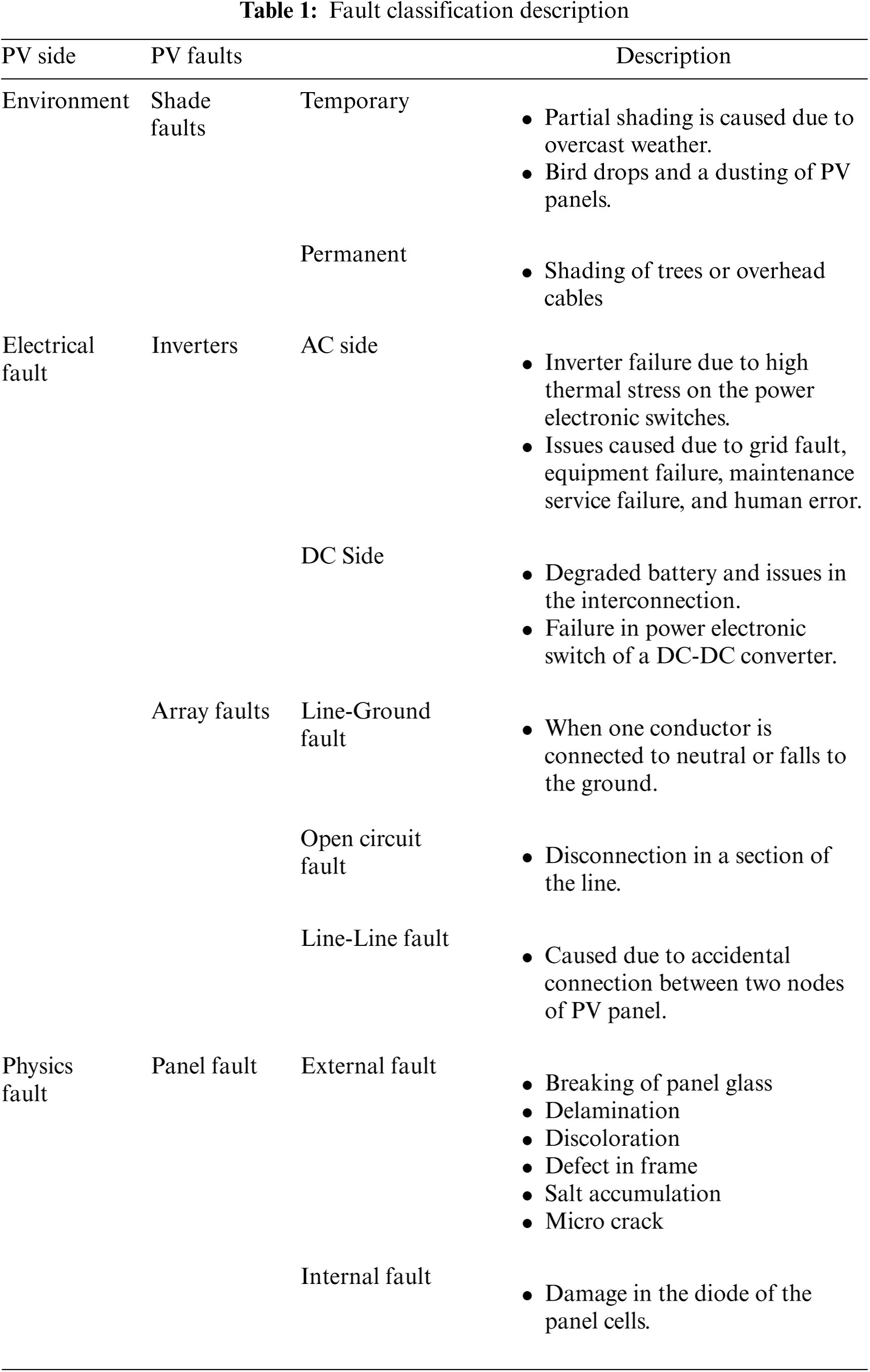
In the case of normal operation, the output power of the PV array is very close to the predictive power. However, during the real-world application, may factor impacts the operation of PV array which in return reduces the efficiency. The factors are classified as a fault which is categorized based on system location as presented in Fig. 2 [22]. Further, a brief description of different faults is presented in Tab. 1. Identification of these faults is necessary for appropriate maintenance of the PV system [23]. Many techniques have been developed for the identification of different faults. The techniques assist in improving the reliability and lifetime of PV systems [24]. An overview of different fault detection techniques is presented in Fig. 2.

Figure 2: Fault classification in grid-connected PV system [22]
Further, the detection techniques as represented in Fig. 3 are as follow:

Figure 3: Fault detection techniques
Electrical Characteristics:
• Climate Independent Data Technique: The technique is independent of any climate data such as irradiance and temperature. Fault detection is performed by external devices such as LCR meters and signal generators [25].
• V-I-based Techniques: The V-I characteristics of the PV panel are monitored to identify the fault. Real-time monitoring is performed by using a microcontroller and fill factor, shunt resistance (
• Power Loss Analysis: The power loss of the PV panel is analyzed to identify the fault. The method was proposed by [26], in which the power loss is calculated by comparing the monitored data with a simulated one.
• Machine Learning-based detection: The different characteristics of the PV panel are recorded to create a database and based on the fault in the panel the real-time data is compared with the pre-existing databases to identify the fault [27].
• Residual current monitoring: In this method, the amount of current entering the PV panel and the amount of current leaving the panel are monitored. The current-carrying conductor is used for monitoring purposes.
• Frequency Spectrum Analysis: This method is used for the analysis of faults with lower frequency content. In the case of irradiance variation, partial shading of the noise from the frequency is below
Infrared Thermal Imaging: Thermal imaging is a popular method for fault detection of PV panels. This method is based on the identification of localized heat spots in case of panel-based faults, i.e., delamination, panel crack, etc. [28,29]. Even for the inverters and other systems, thermography can help in the identification of faults such as poor contact, short circuit, etc. [30,31]. During thermal image-based fault detection, the failure spot emerges as a bright spot. The thermal imaging can be performed in two methods (a) Forward biased and (b) Reverse biased imaging techniques. In forwarding biased technique the real-time thermography-based monitoring of forwards biased connected module is performed. This method is used for the detection of faults such as hot spots, loose connections, etc. Whereas in reverse biased the modules are connected in reverse biased with the system and fault such as ohmic shunt is monitored.
Visual-based Inspection: It is a basic and initial stage to identify the fault. As per the IEEE 61215 standards, the visual inspection needs to be performed under 1000 lux light. Inspection needs to be performed with different angles to avoid any error due to the deflection of light. A brief regarding vision inspection is presented in [32].
Ultrasonic-based inspection: This method is based on the identification of vibration in ultrasonic signals. It is generally used for the detection of cracks in PV modules. The most commonly used ultrasonic methods are (a) pulse-echo and (b) transmission methods. The ultrasonic pulse transducer is moved along the X-Y axis of the module [33]. In the case of the pulse echo method, the reflected signal is recorded and analyzed. Whereas during the transmission method, an attenuated signal is recorded for analysis.
Electroluminescence Imaging technique: During the electroluminescent imaging, the excess carrier charges are recombined in the solar cell. The current injection causes excitation which initiates the EL effect [34]. The excitation can also be initiated by the process of photoluminescence.
Component Fault for power Converters: In power electronics converters the faults are generally caused due to the passive component’s failure or due to the stress on the power electronics switches. The passive components may cause short or open circuit faults. However, the power electronic switch-based fault can be analyzed by thermal and mechanical stress analysis. Majorly the fault detection technique can be classified into (a) model-based, and (b) model-free approaches. The model-based approach relies on the parameter estimation or state observer approach [35]. The knowledge of system and signal processing techniques is required for these approaches. Whereas in a model-free approach the data-based learning is required to identify a particular operating condition.
Grid-based failures: The failure at the grid end or maintenance break may cause the grid to disconnect from the distributed generation unit. This type of fault causes the DGs to operate in an islanded mode of operation. Many islanding detection techniques have been implemented by the researcher in the literature [36–38]. The islanding detection techniques can be classified as active, passive, and hybrid techniques.
4 Proposed Fault Detection Algorithm
Faults impact the current and the voltage at PCC for the grid-connected PV system. The impacts of these faults can be analyzed by assessment of current and voltage signals. For assessment, wavelet transform is used to break down the signal into various features. The features add accuracy by identifying minor fluctuations in the signal. Wavelet transform [39,40] is a spectrum-based analysis method where the signal is decomposed into a set of oscillatory functions which are known as a wavelet. Further, the wavelet transform is used to obtain different features by decomposition and reconstruction of the signal. Once the features are extracted for different operating conditions, a database of classifications is established. A decision tree is one of such classification tools that has been used for analysis in our research. The classification techniques follow a tree-based structure with an arrangement from root nodes to the leaf node for sample classification [41] as represented in Fig. 4. The leaf node represents one classification to which a sample is assigned.

Figure 4: Decision tree-based classification
Initially, the classification began at the root node. Further, the movement is performed in the direction of a leaf node and the number of stages is determined by the value of samples. The process involved in the decision tree is Data collection, data preparation (wavelet transform), data analysis, training, and testing. The most commonly used decision tree algorithm techniques are the C4.5 and ID3 algorithms. Both of the techniques are based on the greedy search method.
In the ID3 algorithm [42] the concept learning method is used. The classification criteria are selected in each node based on the unused property with the highest gain. The process is performed until a classified example can be trained to formulate a decision tree. The data is divided into an ordered state. The gain is used to judge if the model selected is providing the optimal path for the divide data. The higher gain value represents a better result for a divided dataset. The entropy can be expressed as:
The probability regarding selected classification i is represented by
The gain of a property A with dataset S can be expressed as:
where all values for attributes A are denoted by

Figure 5: ID3 algorithm of decision tree classification
C4.5 algorithm is another version of the decision tree as represented in Fig. 6. The C4.5 utilizes the information from the gain rate for attribute selection [43]. The decision is pruned for avoiding the overfitting of data. The data splitting can be expressed as:

Figure 6: C4.5 algorithm of decision tree classification
The samples S are divided into v values for A. Further, the gain can be calculated as:
5 Simulation and Experimental Analysis
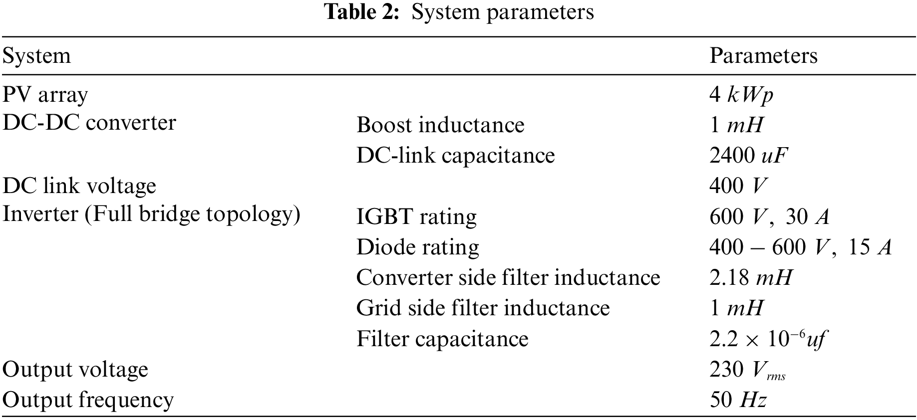
To validate the monitoring and maintenance of Grid-connected PV systems, a single-phase grid-connected PV system is simulated with MATLAB/Simulink. A
The abnormality in the grid-connected PV system are monitored used a decision tree Algorithm. For the purpose of training
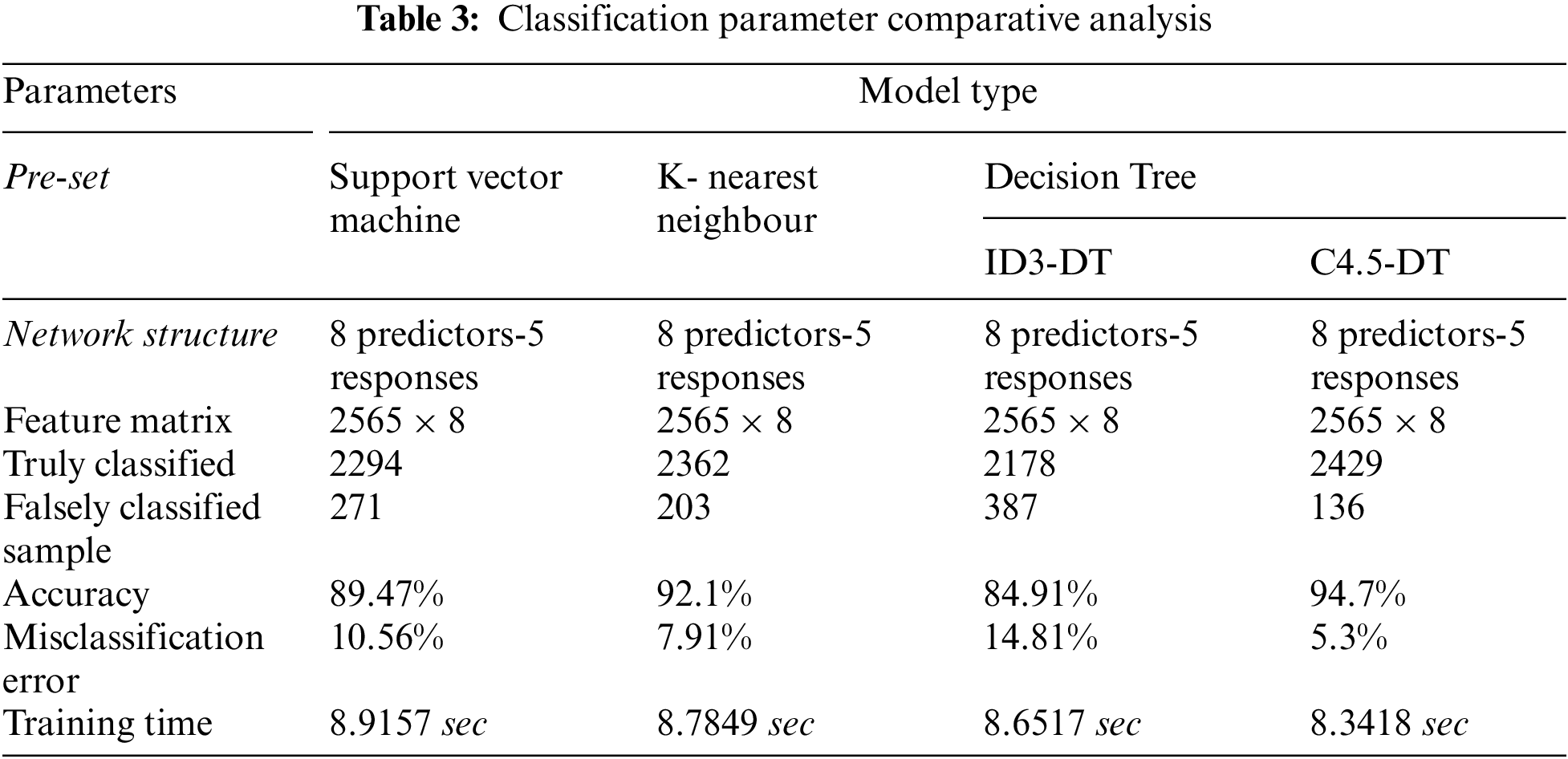
For the Tab. 3, it can be concluded that the decision tree classifier performed faster training with reduced misclassification. The result of the trained classifier is illustrated in the confusion matrix as shown in Fig. 7. For the result in Fig. 7a, it can be deduced that out of


Figure 7: Confusion matrix for decision tree classifier
Case I: Fault not Clear during Standard Time
In this condition, a fault is injected into the system at

Figure 8: Voltage and current at point of common coupling during case I operation
As per IEC 62116 standard, if the fault is not cleared in

Figure 9: Active and reactive power during case I operation

Figure 10: Trip and fault detection signal during case I operation
Case II: Fault clear during standard time
In this condition, a fault is injected into the system at

Figure 11: Voltage and current at point of common coupling during case II operation

Figure 12: Active and reactive power during case II operation

Figure 13: Trip and fault detection signal during case I operation
Further, for the validation of the result, experimental testing is performed. The experimental setup is illustrated in Fig. 14. The operation of the PV array is simulated with the help of an Agilent Keysight solar simulator which is further connected with a Semikron inverter. The inverter is controlled using Typhoon Hardware in the Loop unit. The grid interface is connected to the output of the inverter and an AC load is connected parallelly. The field programmable gate array (FPGA) devices are used for implementing the trained classifier due to their advantage with speed, and their ability of direct hardware execution. Another important factor in using FPGAs is their re-configurability and reusable hardware architectures for rapid prototyping of the digital system. The Altera DE2 FPGA board along with the Quartus programming software is utilized in this project. The task is to load the VHDL program of the trained classifier using ModelSim HDL Simulator to the FPGA, and after loading the program on the kit and carrying out the assignment of the monitored output to the GPIO of the board we have connected the GPIO ports of the FPGA board to an oscilloscope to be able to experimentally examine the outputs. Further, these outputs are also used in maintenance management with the grid connected systems. But before being able to download the VHDL program simulated in MODELSIM the Quartus software must be used in order to be able to download the last to the FPGA where the program must be compiled in the Quartus environment. Programmable logic device design software produced by Altera [44]. Quartus enables analysis and synthesis of HDL designs, which enables the developer to compile their designs, perform timing analysis, simulate a design’s reaction, and configure the target device with the programmer. To analyse the results, the test is performed with a

Figure 14: Experimental setup
The normal operating condition of the grid-connected PV system is illustrated in Fig. 15. It can be observed that the voltage at PCC is

Figure 15: Normal mode of operation
The fault clearance mode of the grid-connected PV system is illustrated in Fig. 16. It can be observed that the voltage at PCC is

Figure 16: Fault clearance in grid standard-based time
Renewable energy being the future of power generation has been a prime concern for the researcher’s development, and countries such as the kingdom of Saudi Arabia have been pushing hard to achieve the goal. In this research, the prime focus is to understand the faults that commonly occur while operating grid-connected PV system in harsh condition and based on the fault to study the fault detection techniques which are currently being implemented. Based on the study an advance data-driven machine learning algorithm is implemented to enhance the fault detection time so that the system can inform the controller and attempt to recover the system. The training accuracy of the machine learning classifier with the extracted data is around 94.7% and the misclassification error during testing with the trained classifier is 4.15. In case of system recovery failure, the faulty section is disconnected, and emergency maintenance is scheduled. Whereas if the fault was cleared by the recovery action of the controller, then the maintenance team is informed so that they can perform an in-depth diagnostic check when the normal maintenance is scheduled. Further, the work can be extended to develop a power management approach based on the monitored system condition. Besides, the reliability analysis can be performed to asses the lifetime of the converter and other components while operating in such harsh environment conditions.
Acknowledgement: The authors extend their appreciation to the Deputyship for Research & Innovation, Ministry of Education in Saudi Arabia for funding this research work through the project number “IFPHI-022-135-2020” and King Abdulaziz University, DSR, Jeddah, Saudi Arabia.
Funding Statement: Funding for this study was received from the Deputyship for Research & Innovation, Ministry of Education in Saudi Arabia for funding this research work through the project number “IFPHI-022-135-2020” and King Abdulaziz University, DSR, Jeddah, Saudi Arabia.
Conflicts of Interest: The authors declare that they have no conflicts of interest to report regarding the present study.
1. T. Kurbatova and T. Perederii, “Global trends in renewable energy development,” in 2020 IEEE KhPI Week on Advanced Technology (KhPIWeek), Kharkiv, Ukraine, pp. 260–263, 2020. [Google Scholar]
2. L. J. Sawin, Renewables 2017 global status report. France, 2016. [Online]. Available: https://inis.iaea.org/search/search.aspx?orig_q=RN:48058284. [Google Scholar]
3. P. G. Duque-escobar, “Communication from the commission to the european parliament, the council, the european economic and social committee and the committee of the regions,” European Commission, Brussels, 25th October 2011. [Google Scholar]
4. Z. S. AlOtaibi, H. I. Khonkar, A. O. AlAmoudi and S. H. Alqahtani, “Current status and future perspectives for localizing the solar photovoltaic industry in the kingdom of Saudi Arabia,” Energy Transitions, vol. 4, no. 1, pp. 1–9, 2020. [Google Scholar]
5. A. Faruqui, R. Hledik, G. Wikler, D. Ghosh, J. Prijyanonda et al., “Bringing demand-side management to the kingdom of Saudi Arabia,” The Brattle Group, vol. 1, pp. 1–319, 2011. [Google Scholar]
6. Renewable Energy Project Development Office (REPDO“Saudi Arabia national renewable energy program,” in 1th IEA IEF OPEC Symp. on Energy Outlooks, Riyadh, Saudi Arabia, 2019. [Google Scholar]
7. M. Mutlaq and R. Sreerama Kumar, “Environmental economic dispatch of thermal power plants in Saudi Arabia: A case study,” in 2019 Industrial & Systems Engineering Conf. (ISEC), Jeddah, Saudi Arabia, pp. 1–6, 19–20 Jan. 2019. [Google Scholar]
8. W. Chine, A. Mellit, A. M. Pavan and S. A. Kalogirou, “Fault detection method for grid-connected photovoltaic plants,” Renewable Energy, vol. 66, pp. 99–110, 2014. [Google Scholar]
9. H. R. Baghaee, D. Mlakić, S. Nikolovski and T. Dragicević, “Support vector machine-based islanding and grid fault detection in active distribution networks,” IEEE Journal of Emerging and Selected Topics in Power Electronics, vol. 8, no. 3, pp. 2385–2403, 2019. [Google Scholar]
10. M. A. Khan, A. Haque and V. S. B. Kurukuru, “Intelligent transition control approach for different operating modes of photovoltaic inverter,” IEEE Transactions on Industry Applications, vol. 58, pp. 1–9, 2022. [Google Scholar]
11. W. Chine, A. Mellit, V. Lughi, A. Malek, G. Sulligoi et al., “A novel fault diagnosis technique for photovoltaic systems based on artificial neural networks,” Renewable Energy, vol. 90, pp. 501–512, 2016. [Google Scholar]
12. M. A. Khan, A. Haque and V. S. B. Kurukuru, “Dynamic voltage support for low voltage ride through operation in single-phase grid-connected photovoltaic systems,” IEEE Transactions on Power Electronics, vol. 36, no. 10, pp. 12102–12111, 2021. [Google Scholar]
13. M. A. Khan, A. Haque and V. S. B. Kurukuru, “Enhancement of fault ride through strategy for single-phase grid-connected photovoltaic systems,” in 2019 IEEE Industry Applications Society Annual Meeting, Baltimore, MD, USA, pp. 1–6, 2019. [Google Scholar]
14. M. A. Khan, A. Haque, V. S. B. Kurukuru and S. Mekhilef, “Advanced control strategy with voltage sag classification for single-phase grid-connected photovoltaic system,” IEEE Journal of Emerging and Selected Topics in Industrial Electronics, vol. 3, no. 2, pp. 1, 2020. [Google Scholar]
15. A. Haque, K. V. S. Bharath, M. A. Khan, I. Khan and Z. A. Jaffery, “Fault diagnosis of photovoltaic modules,” Energy Science & Engineering, vol. 7, no. 3, pp. 622–644, 2019. [Google Scholar]
16. A. C. Márquez, P. M. de León, J. F. G. Fernández, C. P. Márquez and M. L. Campos, “The maintenance management framework,” Journal of Quality in Maintenance Engineering, vol. 15, no. 2, pp. 167–178, 2009. [Google Scholar]
17. A. S. B. Tam and J. W. H. Price, “A generic asset management framework for optimising maintenance investment decision,” Production Planning & Control, vol. 19, no. 4, pp. 287–300, 2008. [Google Scholar]
18. M. A. Hassanain, T. M. Froese and D. J. Vanier, “Framework model for asset maintenance management,” Journal of Performance of Constructed Facilities, vol. 17, no. 1, pp. 51–64, 2003. [Google Scholar]
19. Q. Hao, Y. Xue, W. Shen, B. Jones and J. Zhu, “A decision support system for integrating corrective maintenance, preventive maintenance, and condition-based maintenance,” in Construction Research Congress 2010: Innovation for Reshaping Construction Practice, Banff, Alberta, Canada, pp. 470–479, 2010. [Google Scholar]
20. M. Shayestegan, M. Shakeri, H. Abunima, S. M. S. Reza, M. Akhtaruzzaman et al., “An overview on prospects of new generation single-phase transformerless inverters for grid-connected photovoltaic (PV) systems,” Renewable and Sustainable Energy Reviews, vol. 82, pp. 515–530, 2018. [Google Scholar]
21. M. A. Sanz-Bobi, “Use, Operation and Maintenance of Renewable Energy Systems,” in Green Energy and Technology, Cham: Springer, vol. 1, pp. 1–385, 2014. [Google Scholar]
22. V. S. B. Kurukuru, F. Blaabjerg, M. A. Khan and A. Haque, “A novel fault classification approach for photovoltaic systems,” Energies, vol. 13, no. 2, pp. 308, 2020. [Google Scholar]
23. L. Rouani, M. F. Harkat, A. Kouadri and S. Mekhilef, “Shading fault detection in a grid-connected PV system using vertices principal component analysis,” Renewable Energy, vol. 164, pp. 1527–1539, 2021. [Google Scholar]
24. F. Harrou, Y. Sun, B. Taghezouit, A. Saidi and M. E. Hamlati, “Reliable fault detection and diagnosis of photovoltaic systems based on statistical monitoring approaches,” Renewable Energy, vol. 116, pp. 22–37, 2018. [Google Scholar]
25. T. Takashima, J. Yamaguchi, K. Otani, K. Kato and M. Ishida, “Experimental studies of failure detection methods in PV module strings,” in 2006 IEEE 4th World Conf. on Photovoltaic Energy Conf., Waikoloa, HI, pp. 2227–2230, 2006. [Google Scholar]
26. S. R. Madeti and S. N. Singh, “Comparative analysis of solar photovoltaic monitoring systems,” in AIP Conf. Proc., Andhra Pradesh, India, pp. 020116, 2017. [Google Scholar]
27. M. Hussain, M. Dhimish, S. Titarenko and P. Mather, “Artificial neural network based photovoltaic fault detection algorithm integrating two bi-directional input parameters,” Renewable Energy, vol. 155, pp. 1272–1292, 2020. [Google Scholar]
28. R. H. Fonseca Alves, G. A. de Deus Júnior, E. G. Marra and R. P. Lemos, “Automatic fault classification in photovoltaic modules using convolutional neural networks,” Renewable Energy, vol. 179, pp. 502–516, 2021. [Google Scholar]
29. V. S. B. Kurukuru, A. Haque, M. A. Khan and A. K. Tripathy, “Fault classification for photovoltaic modules using thermography and machine learning techniques,” in Int. Conf. on Computer and Information Sciences (ICCIS), Sakaka, Saudi Arabia, pp. 1–6, 2019. [Google Scholar]
30. Irshad, Zainul Abdin Jaffery, Ahteshamul Haque, Ashwani Kumar Dubey, Mohammed Ali Khan, V. S. Bharath, Kurukuru “Thermography based real time intelligent condition monitoring system for solar power inverter,” in 2019 Int. Conf. on Power Electronics, Control and Automation (ICPECA), New Delhi, India, pp. 1–6, 2019. [Google Scholar]
31. M. Cubukcu and A. Akanalci, “Real-time inspection and determination methods of faults on photovoltaic power systems by thermal imaging in Turkey,” Renewable Energy, vol. 147, pp. 1231–1238, 2020. [Google Scholar]
32. G. Ball, B. Brooks, J. Johnson, J. Flicker, A. Rosenthal et al., “Final Report: Inverter Ground-Fault Detection “Blind Spot” and Mitigation Methods,” Solar America Board for Codes and Standards, University of Central Florida, 2013. [Google Scholar]
33. A. Ndiaye, C. M. F. Kébé, P. A. Ndiaye, A. Charki, A. Kobi et al., “A novel method for investigating photovoltaic module degradation,” Energy Procedia, vol. 36, pp. 1222–1231, 2013. [Google Scholar]
34. T. Kirchartz, A. Helbig, W. Reetz, M. Reuter, J. H. Werner et al., “Reciprocity between electroluminescence and quantum efficiency used for the characterization of silicon solar cells,” Progress in Photovoltaics: Research and Applications, vol. 17, no. 6, pp. 394–402, 2009. [Google Scholar]
35. M. A. Khan, A. Haque, V. S. B. Kurukuru and S. Mekhilef, “Islanding detection techniques for grid-connected photovoltaic systems-A review,” Renewable and Sustainable Energy Reviews, vol. 154, pp. 111854, 2022. [Google Scholar]
36. M. A. Khan, V. S. B. Kurukuru, A. Haque and S. Mekhilef, “Islanding classification mechanism for grid-connected photovoltaic systems,” IEEE Journal of Emerging and Selected Topics in Power Electronics, vol. 9, no. 2, pp. 1966–1975, 2021. [Google Scholar]
37. A. Fatama, A. Haque and M. A. Khan, “A multi feature based islanding classification technique for distributed generation systems,” in 2019 Int. Conf. on Machine Learning, Big Data, Cloud and Parallel Computing (COMITCon). IEEE, Faridabad, pp. 160–166, 2019. [Google Scholar]
38. M. A. Khan, A. Haque, V. S. B. Kurukuru and M. Saad, “Islanding detection method based on wavelet transform and neural networks for single phase grid connected photovoltaic systems,” Renewable and Sustainable Energy Reviews, vol. 154, pp. 111854, 2022. [Google Scholar]
39. V. S. B. Kurukuru, A. Haque and M. A. Khan, “Fault detection in single-phase inverters using wavelet transform-based feature extraction and classification techniques,” in Mishra S., Sood Y., Tomar A. (eds) in Applications of Computing, Automation and Wireless Systems in Electrical Engineering. Lecture Notes in Electrical Engineering, vol. 553. Singapore: Springer, pp. 649–661, 2019. [Google Scholar]
40. V. S. B. Kurukuru, A. Haque, A. K. Tripathi and M. A. Khan, “Condition monitoring of IGBT modules using online TSEPs and data-driven approach,” International Transactions on Electrical Energy Systems, vol. 31, no. 8, pp. e12969, 2021. [Google Scholar]
41. S. B. Kotsiantis, “Decision trees: A recent overview,” Artificial Intelligence Review, vol. 39, no. 4, pp. 261–283, 2013. [Google Scholar]
42. K. J. Cios and N. Liu, “A machine learning method for generation of a neural network architecture: A continuous ID3 algorithm,” IEEE Transactions on Neural Networks, vol. 3, no. 2, pp. 280–291, 1992. [Google Scholar]
43. A. Pourebrahimi, S. Mokhtar, S. Sahami and M. Mahmoodi, “Status detection and fault diagnosing of rotatory machinery by vibration analysis using data mining,” in 2010 2nd Int. Conf. on Computer Technology and Development, Cairo, Egypt, pp. 131–135, 2010. [Google Scholar]
44. M. A. Khan, A. Haque, and V. S. B. Kurukuru, “Intelligent control of a novel transformerless inverter topology for photovoltaic applications,” Electrical Engineering, vol. 102, no. 2, pp. 627–641, 2020. [Google Scholar]
 | This work is licensed under a Creative Commons Attribution 4.0 International License, which permits unrestricted use, distribution, and reproduction in any medium, provided the original work is properly cited. |