DOI:10.32604/cmc.2022.026111
| Computers, Materials & Continua DOI:10.32604/cmc.2022.026111 | |
| Article |
Compact Interlaced Dual Circularly Polarized Sequentially Rotated Dielectric-Resonator Antenna Array
Department of Electrical Engineering, College of Engineering, Majmaah University, AL-Majmaah, 11952, Saudi Arabia
*Corresponding Author: Yazeed Qasaymeh. Email: y.qasaymeh@mu.edu.sa
Received: 15 December 2021; Accepted: 02 March 2022
Abstract: In this study, a compact 2 × 2 interlaced sequentially rotated dual-polarized dielectric-resonator antenna array is proposed for 5.8 GHz applications. The array is composed of a novel unit elements that are made of rectangular dielectric resonator (RDR) coupled to an eye slot for generating the orthogonal modes,
Keywords: Antenna array; compact; dielectric resonator antenna; dual polarized; interlaced; sequential rotation
Dual-circularly polarized (CP) antennas have been investigated recently because of their ability to improve the channel capacity of wireless devices and enhance their spectral efficiency [1]. When designing a practical dual-polarized antenna, a wide operating band, high isolation, and low cross-polarization are the major characteristics. Furthermore, antennas with low profiles are highly desired because miniaturization is the leading trend.
In meanwhile, The sequentially rotated (SR) array geometry first introduced by [2] offers several advantages, such as enhancing the circular-polarization performance, and improving the polarization purity, impedance matching, beam forming, and pattern symmetry across wider bandwidths [3,4]. However, with dual-polarization architectures, ports isolation, compactness, and design simplicity are important characteristics that should be considered.
Few dual-polarized (DP) SR dielectric-resonator antenna (DRA) arrays have been re-ported in the literature. Xie et al. (2016) proposed a 2 × 2 array that operates at 5.94– 6.54 GHz for port 1 and 5.84–6.51 GHz for port 2 [5]. The 80 × 80 mm2 array gain was 11.5 dB with ports isolation of 34 dB. Dwivedy et al. (2017) employed a Wilkinson power divider to design a 190 × 82 mm2 2 × 1 array, with 190 × 82 mm2 operating on the 6–6.6-GHz band with 40-dB ports isolation [6]. The peak gain was 12.5 dB. Recently, Kowalewski et al. (2020) proposed a multilayer 2 × 2 array to operate at 28 GHz with a peak gain of 8.49 dBi [7].
Interlacing the feeding network for an SR array will boost the DP SR array’s performance in various aspects. First, the spacing of the resonating elements can be minimized by interlacing the feeding network [8]. In addition, operating with signals of different frequencies is another prime advantage that makes it compatible with multiple-input multiple-output (MIMO) systems [9].
In view of these considerations, the objectives of this study are twofold. First, a novel resonating element composed of an eye-shaped slot coupling a RDR is proposed to obtain the CP radiation. A miniaturized interlaced SR DP DRA array, operating at the IEEE 802.11 WLAN band with some gain enhancement and port isolation, is the second objective.
The manuscript is organized as follows: The geometry of the proposed single radiating element and parametric study is presented in Section 2. The interlaced SR-array layout is described in Section 3. The results and discussion are presented in Section 4. Finally, conclusions are drawn in Section 5.
A novel resonating element composed of an eye-shaped slot coupling an RDR is proposed in this section. The proposed resonating element is expected to exhibit CP radiation. In addition, the design simplicity and compactness should be considered. Fig. 1 depicts an eye slot carved on the bottom plane and fed by a microstrip etched onto the opposite side. The RDR is mounted over the eye slot at the bottom plane and is omitted here to better visualize the slot fundamentals. The eye slot can be modeled using two intersecting circles of radii (r). The circle slot dimensions in Eq. (1), reported by [10,11], were used to estimate the eye-slot resonance frequency. Eq. (1) reveals that the circular-slot antenna can support the different resonance modes that are required for CP radiation.
where
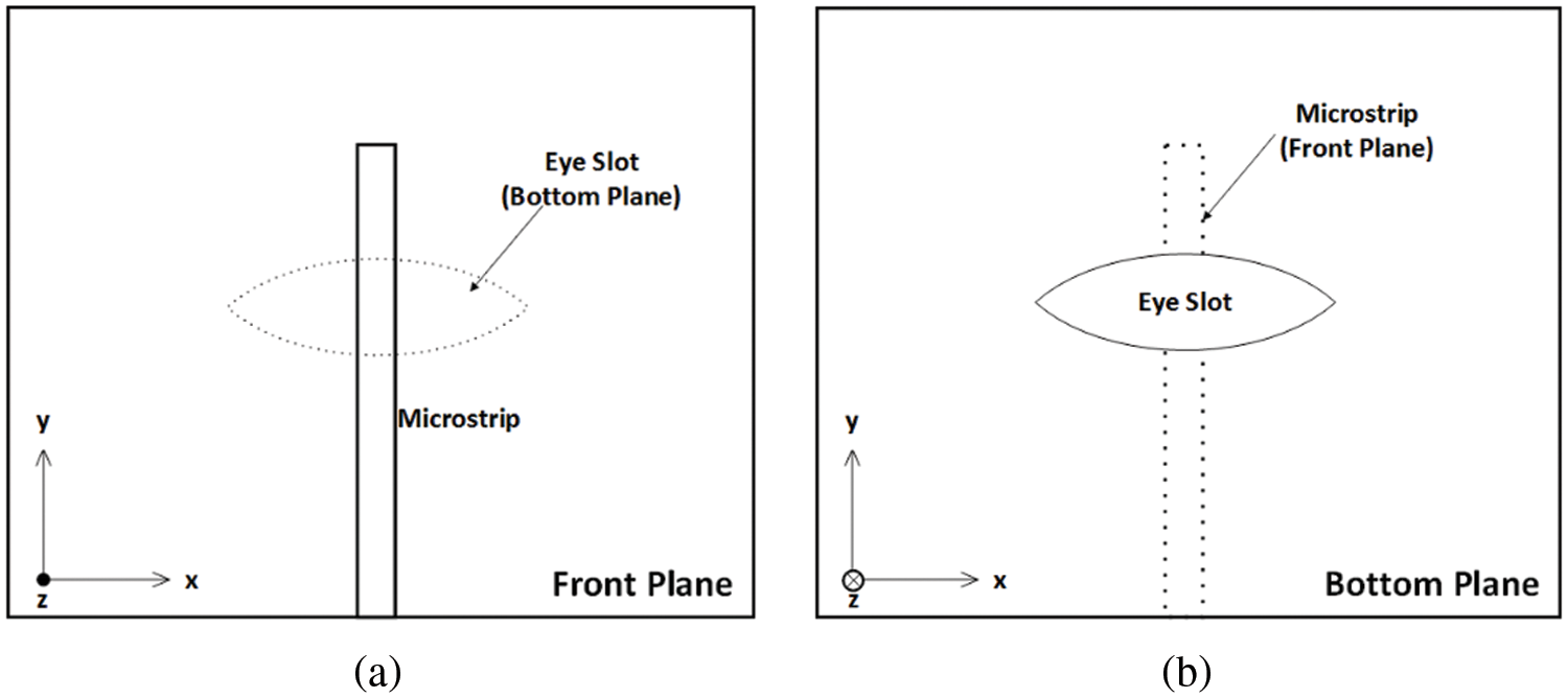
Figure 1: Proposed single resonator: (a) Front plane, (b) Bottom plane
The effective radius of the slot can be calculated by Eq. (2):
where h is the substrate height.
Fig. 2 depicts the 3D geometry of the proposed resonator element composed of an RDR coupled to an eye slot on the bottom plane. The RDR shape was selected because its dimensions can be chosen independently. Once the RDR is excited using a slot at the bottom plane, the
where
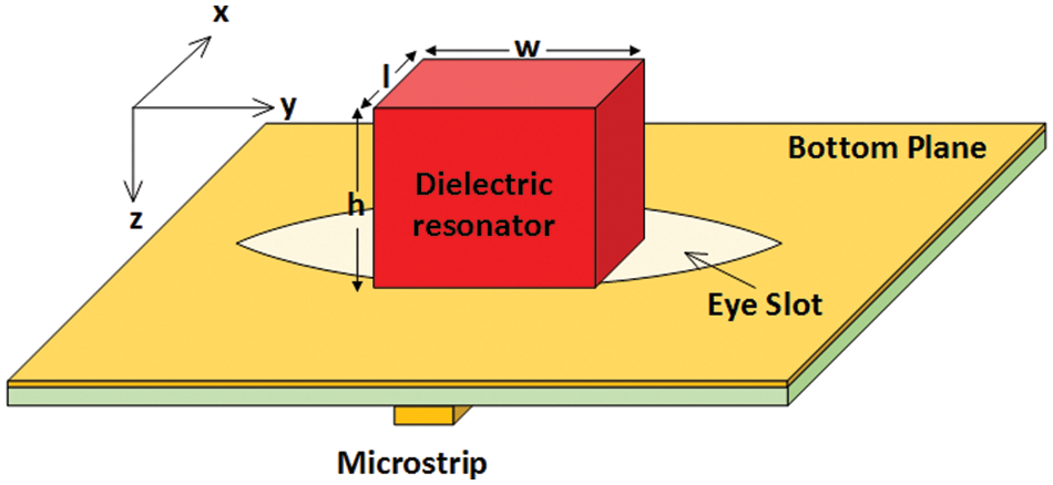
Figure 2: 3D geometry of the proposed resonating element
2.2 Single-Element Parametric Study
In this section, the relationship between the design sub-elements is clarified to achieve a CP-matched DRA. Fig. 3 depicts the prototype single-resonating element that was modeled using the CST Microwave Studio suite simulation software. The substrate was modeled as an RO4003C substrate with a permittivity of 3.38 and a thickness of 0.813 mm. An alumina material with a dielectric constant of 10 was used to model the RDR. The parametric study was carried out on the prototype model for the optimum performance at 5.8 GHz.
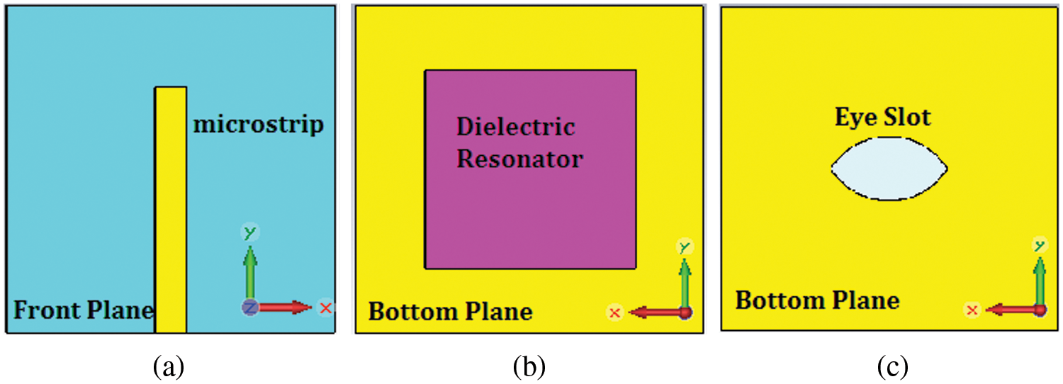
Figure 3: Prototype single-element resonator used for the parametric study: (a) Microstrip on the front plane, (b) RDR mounted over the slot in the bottom plane, (c) Eye slot beneath the RDR
Fig. 4 depicts the reflection coefficient of variation in accordance with the circle radii (r) intersected to form the eye slot. The optimum resonance occurs if the radius is 5 mm with −24.58 dB at 5.795 GHz, while keeping the RDR dimensions constant at 6 × 6 × 6 mm3 unchanged. It can be observed that as the radii increase, the resonant frequency decreases with more reflection-coefficient matching. Fig. 5 shows the Smith chart for the optimum resonance. A small loop occurs at the loci that indicate CP radiation. In addition, a good matching of 48.62 Ω can be observed at 5.795 GHz.

Figure 4: Reflection coefficients of variations with respect to the circle radii forming the eye slot

Figure 5: Simulated smith chart at the optimum resonance frequency
Fig. 6 presents the AR variations in accordance to the radii alteration. A good CP purity is achieved at the optimum resonance frequency of 5.795 GHz. In addition, once the frequency increases, the resonant frequency shifts toward the left.

Figure 6: Effect of varying the slot radii on the AR
Fig. 7 shows the 3D field radiation pattern of the proposed antenna. The gain was approximately 4.1 dBi with a directive radiation pattern. The simulated co-polarized electric field is higher than the cross-polarized electric field for the proposed single radiating element at an optimum resonance frequency of 5.795 GHz by 20 dB. The magnitude of the cross-polarized electric field was −17 dB.

Figure 7: 3D radiation pattern of the proposed resonating element
Fig. 8 depicts the excited modes of the proposed resonating element. At the optimum resonance frequency, two excited orthogonal modes are required for CP radiation at the optimum resonance frequency, namely,

Figure 8: Electric-field distribution for the proposed resonator
The array size can be minimized by interlacing the radiation elements. Based on this fact, the 2 × 2 DP SR geometry depicted in Fig. 9 is proposed. The power provided by port 1 is divided into two equivalent amounts to feed the horizontal (along the x-axis) resonating elements. Similarly, the power provided by port 2 is fed to the vertical (along the y-axis) resonating elements. Hence, the polarization modes are created individually by ports 1 and 2. A quarter-wavelength transformer is employed to minimize the attenuation and consequently improve the coupled power to the slots at the bottom plane. Once designing an interlaced dual polarized array, the feeding network arms overlapping is a critical issue that should be taken into consideration while keeping a compact array size.
Fig. 9a presents the impedances of the feeding networks, as a single quarter-wavelength transformer is employed. Fig. 9b depicts the length of each segment. Fig. 9c depicts the angle rotation at the coupling slots. The figure shows that two orthogonal signals can be manipulated at the same frequency. In [14], it was experimentally proven that the optimal element spacing for 2 × 2 SR arrays was

Figure 9: Proposed array geometry: (a) Line impedances, (b) Lines and substrate lengths, (c) Angle at each eye slot
The current distribution over the feeding network was studied to ensure that the coupling slots were fed with sufficient power. Figs. 10a and 10b depict the current distribution over the feeding network. As can be seen from the figure, a sufficient current will reach each radiating slot. Hence, sufficient power is expected to reach the coupling slots. Moreover, it can be observed that the current rotates counterclockwise. For port 1, the angles lie on the horizontal plane. Meanwhile, for port 2, the angles lie on the vertical plane. Thus, an RHCP is obtained from port 1, and an LHCP is expected from port 2.

Figure 10: Current distribution over the feed network: (a) Excited from port 1, (b) Excited from port 2
The power allocations over the feeding array are shown in Fig. 11. As can be seen from Fig. 11a, the power nodes take their places exactly over the vertical coupling slots, once they are fed by port 2. In addition, the power nodes take their places just over the horizontal slot, as can be seen from Fig. 10b, if they are fed by port 1. These results will maximize the radiated gain of the array.

Figure 11: Power allocation over the feeding network: (a) Power distribution for port 1, (b) Power distribution for port 2
Fig. 12 depicts the fabricated 2 × 2 DP SR array. The array dimensions measures 35 × 35 mm2. The resonating element dimensions, optimized in Section 2.2, are used to diagram the array. The RDR dimensions were 6 × 6 × 6 mm3. The two circles forming the eye-slot radii are 5.5 mm. Fig. 12a depicts the dual-feeding topology on the front plane. As the RO4003C substrate was used for fabrication, the line width was 1.898 mm for 50 Ω and 0.482 mm for 100 Ω. The width of the quarter-wavelength transformer of 70.7 Ω is 1.035 mm and its length is 7.9 mm. Fig. 12b shows the eye slots in the bottom plane while omitting the RDR. Fig. 12c shows the RDRs located above the slots at the bottom plane.
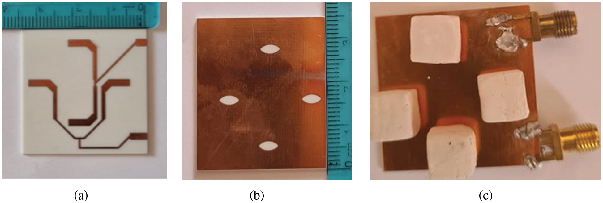
Figure 12: Fabricated 2 × 2 SR array: (a) Front plane showing the feeding network, (b) Bottom plane showing the eye slots, (c) Bottom plane showing the drs located over the coupling slots
Fig. 13 depicts the simulated and measured reflection coefficients of the proposed array. The simulated and measured results were in good agreement because of the accuracy of setting the simulation and measurement environments. For port 1, the minimal simulated resonance of −26.03 dB occurs at 5.822 GHz within a bandwidth range of 5.769–5.913 GHz. However, the measured bandwidth ranges from 5.766 to 5.911 GHz, with a minimal value of −26.78 dB at 5.816 GHz. For port 2, the bandwidth ranges from 5.788 to 5.922 GHz with a minimal resonance of −26.53 dB at 5.838 GHz for the simulation. Whereas, the minimal measured resonance of −26.28 dB occurs at 5.833 GHz within a bandwidth range of 5.788–5.919 GHz. The port isolation is shown in Fig. 14. The isolation at 5.8 GHz was −33.51 dB.

Figure 13: Simulated and measured reflection coefficients: (a) At port 1, (b) At port 2

Figure 14: Simulated and measured |S21| between port 1 and port 2
The simulated and measured radiated electric fields for ports 1 and 2 at 5.8 GHz are depicted in Figs. 15a and 15b, respectively. Again, the simulations and measurements are in good agreement. For port 1, the co-polarized fields are higher than the cross-polarized ones; i.e., an RHCP was achieved. For port 2, the cross-polarized fields are higher than the co-polarized ones; i.e., an LHCP was attained. These results confirm the validity of the proposed array for acquiring dual-CP resonance by feeding the resonating elements using two ports and having proper interlaced resonating-element alignment. Figs. 16a and 16b depicts the simulates and measured magnetic fields for both ports at 5.8 GHz. The magnetic field results agrees with the ones provided in Fig. 15 that dual polarized resonance is achieved. Again, the agreement between the simulated and measured values were fairly good. The pattern difference between the results from both ports was minimal.

Figure 15: Radiation patterns in the

Figure 16: Radiation patterns in the
Fig. 17 depicts the simulated and measured gains and ARs for both ports. The maximum measured gains obtained from port 1 and port 2 were 8.4 and 8.2 dBi, respectively, compared with the simulated ones, which were 8.58 and 8.3 dBi, respectively. The slight difference between the results obtained from the different ports may be attributed to the matching and fabrication. A notable gain enhancement was obtained with a miniaturized array structure. The measured AR ˂ - 3 dB bandwidth was 2.48% (5.766 to 5.911 GHz) for port 1% and 2.28% (5.788 to 5.922 GHz) for port 2. In general, the simulated and measured results remained consistent.
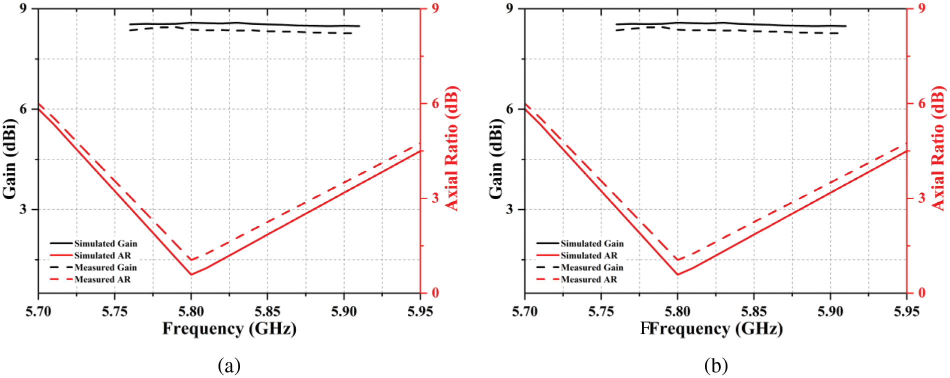
Figure 17: Simulated and measured gains and ARs: (a) Port 1, (b) Port 2
In this study, a DP 2 × 2 SR DRA array has been presented. A novel resonating element composed of an eye-shaped slot coupling an RDR was proposed to obtain CP radiation. A dual interlaced port SR feeding topology was proposed to acquire dual-polarized array. The agreement between the simulated and measured data was fairly good. Tab. 1 presents a comparison between the proposed method and other DP DRA arrays. A significant size reduction was observed, compared with the DP DRA arrays reported in the literature with good gain and ports isolation. For future work, the work can be further extended to enhance the array gain by increasing the number of array elements. Also, the techniques of altering the DR geometry or using copper stacked might be employed for enhancing the bandwidth performance.

Funding Statement: The author would like to thank the Deanship of Scientific Research at Majmaah University for supporting this work under Project Number R-2022-71.
Conflicts of Interest: The author declares that he has no conflicts of interest to report regarding the present study.
1. D. Park and J. Choi, “A Dual-band dual-polarized antenna with improved isolation characteristics for polarimetric SAR applications,” Applied Sciences, vol. 11, no. 21, pp. 10025, 2021. https://doi.org/10.3390/app112110025. [Google Scholar]
2. P. S. Hall, J. S. Dahele and J. R. James, “Design principles of sequentially fed wide bandwidth circularly polarized microstrip antennas,” IEEE Proceedings H Microwaves, Antennas and Propagation, vol. 136, no. 5, pp. 381–389, 1989. https://doi.org/10.1049/ip-h-2.1989.0069. [Google Scholar]
3. R. K. Mongia, I. Ittibipoon and M. Cuhaci, “Low profile dielectric resonator antennas using a very high permittivity material,” Electronics Letters, vol. 30, no. 17, pp. 1362–1363, 1994. https://doi.org/10.1049/el:19940924. [Google Scholar]
4. M. Sukur, M., Rahim and N. Murad, “Bandwidth enhancement of rectangular dielectric resonator antenna using circular slot coupled technique,” Microwave and Optical Technology Letters, vol. 58, no. 3, pp. 505–509, 2016. https://doi.org/10.1002/mop.29604. [Google Scholar]
5. S. Xie, L. Kong, S. Du and S. Zhong, “Dual-polarized quasi-cubic dielectric resonator antenna array,” in Proc. APCAP, Kaohsiung, Taiwan, pp. 253–254, 2016. https://doi.org/10.1109/APCAP.2016.7843193. [Google Scholar]
6. B. Dwivedy, A. Panigrahi and S. K. Behera, “An enhanced gain dual-polarized dielectric resonator antenna array with high isolation for C-band applications,” IETE Journal of Research, vol. 64, no. 5, pp. 602–610, 2018. https://doi.org/10.1080/03772063.2017.1367263. [Google Scholar]
7. J. Kowalewski, A. Jauch, J. Eisenbeis, S. Marahrens, K. Schneider et al., “Dual-polarized dielectric resonator antenna array for 5G mobile radio base stations,” in Proc. EuCAP, Copenhagen, Denmark, pp. 1–4, 2020. https://doi.org/10.23919/EuCAP48036.2020.9135931. [Google Scholar]
8. Y. Shen, S. Zhou, G. Huang and T. Chio, “A compact dual circularly polarized microstrip patch array with interlaced sequentially rotated feed,” IEEE Transactions on Antennas and Propagation, vol. 64, no. 11, pp. 4933–4936, 2016. https://doi.org/10.1109/TAP.2016.2600747. [Google Scholar]
9. R. Ma, Y. Gao, C. Parini and L. Cuthbert, “Dual-polarized turning torso antenna array for massive MIMO systems,” in Proc. EuCAP, Lisbon, Portugal, pp. 1–2, 2015. [Google Scholar]
10. R. Garg, P. Bhartia, I. Bahl and A. Ittipiboon, “Microstrip antenna design handbook,” Artech House Publishers, vol. 1, pp. 1–875, 2001. [Google Scholar]
11. C. A. Balanis, “Antenna theory: Analysis and design,” Wiley, vol. 4, pp. 1–1104, 2016. [Google Scholar]
12. Y. Qasaymeh, A. Almuhaisen and A. S. Alghamdi, “Compact sequentially rotated circularly polarized dielectric resonator antenna array,” Applied Sciences, vol. 11, no. 18, pp. 8779, 2021 https://doi.org/10.3390/app11188779. [Google Scholar]
13. A. Gaya, M. H. Jamaluddin and A. A. Althuwayb, “Ultra-wideband annular ring Fed rectangular dielectric resonator antenna for millimeter wave 5G applications,” CMC-Computers Materials & Continua, vol. 71, no. 1, pp. 1331–1348, 2022. https://doi.org/10.32604/cmc.2022.022041. [Google Scholar]
14. A. R. Weily and Y. J. Guo. “Circularly polarized ellipse-loaded circular slot array for millimeter-wave WPAN applications,” IEEE Transactions on Antennas and Propagation, vol. 57, no. 10, pp. 2862–2870, 2009. https://doi.org/10.1109/TAP.2009.2029305. [Google Scholar]
15. G. Zhou, G. L. Huang, T. H. Chio, J. J. Yang and G. Wei, “Design of a wideband dual-polarization full-corporate waveguide feed antenna array,” IEEE Transactions on Antennas and Propagation, vol. 63, no. 11, pp. 4775–4782, 2015. https://doi.org/10.1109/TAP.2015.2479639. [Google Scholar]
 | This work is licensed under a Creative Commons Attribution 4.0 International License, which permits unrestricted use, distribution, and reproduction in any medium, provided the original work is properly cited. |