DOI:10.32604/cmc.2022.026390
| Computers, Materials & Continua DOI:10.32604/cmc.2022.026390 | |
| Article |
Performance Analysis of Multilayer Coil Based MI Waveguide Communication System
1Department of Electronics and Communications Engineering, Visvesvaraya National Institute of Technology, Nagpur, 440010, India
2Department of Electronics and Communications Engineering, Motilal Nehru National Institute of Technology, Prayagraj, 211002, India
3Department of Civil and Architectural Engineering - Design and Construction, 8000, Aarhus, Denmark
*Corresponding Author: Neeraj D. Bokde. Email: neerajdhanraj@cae.au.dk
Received: 24 December 2021; Accepted: 02 March 2022
Abstract: In the non-conventional media like underwater and underground, the Radio Frequency (RF) communication technique does not perform well due to large antenna size requirement and high path loss. In such media, magnetic induction (MI) communication technique is very promising due to small coil size and constant channel behavior. Unlike the RF technique, the communication range in MI technique is relatively less. To enhance this range, a waveguide technique is already brought in practice. This technique employs single layer coils to enhance the performance of MI waveguide. To further enhance the system functioning, in this paper, we investigated the performance of multi-layer coil (MLC) antenna based MI waveguide communication system in terms of transmission range, path loss, bit error rate (BER) and bandwidth. Besides, the system performance is quantitatively evaluated in three different non-conventional media viz., dry soil, fresh water and wet soil. As compared with the single layer counterpart, the MLC system shows a significant improvement in transmission range, BER even in loosely coupled scenarios and shows a corresponding reduction in path loss. However, the bandwidth is observed to be low (< 1 KHz). In this analysis, the eddy current effects and parasitic capacitance are compared for single and multi-layer coils. It is observed that the proposed system performs better in dry soil medium due to less medium conductivity.
Keywords: Communication; magnetic induction; multilayer coil; waveguide system
Magnetic Induction (MI) communication is a promising technique in the Radio Frequency (RF) challenged environments like underground and underwater (Non conventional media). The conventional RF technique fails to perform well in such media due to large sized antenna requirement, high signal attenuation and dynamic channel conditions [1], whereas MI technique is characterized by constant channel condition, coil-shaped small sized antenna. In this technique, the inductive coupling between the coils is less affected by soil and humidity. Thus it finds applications in bridge scour monitoring, border policing, mine disaster detection, oil and gas pipelines, smart agriculture etc. [2–7]. The MI technique works on the principle of transformer, wherein the adjacent coils communicate by means of near field magnetic induction. Initially, the transmission range of MI system was limited only to a few meters. Over the last decade, the research interest turned towards improving the performance of MI communication in terms of reducing path loss, increasing transmission range and channel capacity and so on.
Zhi sun et al. proposed a waveguide technique for MI communication based underground sensor networks, wherein it is observed that the system performance in terms of path loss and transmission range is better than that of a simple MI transceiver system [1]. Continuing the previous work, the same authors developed a closed form expression to quantize channel and network capacity of the MI waveguide system. It is observed that irrespective of the transmitted power, the channel capacity continues to decrease with an increase of transmission distance. Also, it is found that the MI waveguide system is more reliable in the triangular deployment strategy due to having multiple paths for signal transmission [8]. In the previous two papers, the authors assumed that the MI system path loss is medium and frequency independent. This made the system very simple which is not valid in a practical scenario. To overcome this lack, kisseleff et al. in [9], considered the influence of medium conductivities, eddy currents, channel noise and signal frequency on system path loss. These parameters are very essential to consider at high frequencies for accurate system modelling. It is seen that the MI waveguide system with less inter-coil distance offers a better path loss performance for transmission distances greater than meters. Extending the above work, in [10] the authors introduced spread resonance strategy that improves bandwidth and channel capacity. Herein, the resonant frequencies that slightly differ from that of neighboring coils are allocated to the relay coils. Also, the authors considered the parasitic capacitance that becomes prominent at high frequencies. The results show a significant increase in channel capacity and bandwidth, especially in loosely coupled scenarios where the inter-coil distance is relatively larger.
In the above work, single layer coils are incorporated in system modelling. On the other hand, many other authors worked on multi-layer coil (MLC) based system modelling. Vinay et al. introduced an energy model for MLC based MI transceiver system [11]. Herein, a simple transceiver system (without any relay coils) made up of rectangular MLCs is considered. Based on an energy dissipation model, the authors proved that the energy efficiency of the MLC based MI transceiver system is better than its single layer counterparts. In [12,13], Kim et al. devised a method of analytically estimating the inductance value of the MLCs of any shape. Herein, an MLC is approximated as an aggregation of multiple single layer spirals which are stacked together. By using the simulated results obtained from Ansys Maxwell and calculating the polynomial coefficients using Least Squares Method, the inductance value is accurately estimated. Besides, the accuracy of the model is experimentally validated. In any coil, the combination of conducting wires separated by an insulation forms a capacitance. An array of such combinations exist in MLCs and thus this stray capacitance becomes significant especially in MLCs at high frequencies. This parasitic capacitance value is precisely modelled in [14], wherein, an orthogonal and hexagonal winded MLCs are considered. The stray capacitance in the above two kinds of coils is estimated for standard and flyback windings. Herein, the authors showed that the capacitance value increases with the coil turns, and decreases with the number of coil layers. Besides a significant work is done in literature where many numerical approximation schemes like finite element method (FEM), finite difference method (FDM), and spectral element method (SEM) are developed. Among these, SEM is found to have more accuracy and less computational cost [15–18]. SEM could be used for simulations related to wireless relay networks or waveguides. This technique also finds application in fields like photonic nanojet analysis, computational electromagnetics and so on [19–22]. Besides, the authors utilized a low cost electromagnetic structure that emulates photonic nanojets. The efficiency of this structure is verified using the SEM and the overall performance of the wireless relay networks is enhanced in terms of bit error rate [23].
As compared to the SLCs, the magnetic coupling in a MLC based system is stronger due to higher self-inductance of the coil. By incorporating these MLCs in the MI waveguide system, the system path loss can be further reduced and other performance parameters can also be improved. Moreover, in the current literature [9,24], the authors used MLC in system modelling. However, the influence of layers of coil is considered only in modelling the coil self-inductance but not in the resistance and mutual inductance. Motivated by this observation, in this work we incorporated MLCs to improvise the MI waveguide system performance.
The contributions of this work are mentioned here below:
1. MLCs are incorporated in the MI waveguide system and consequently the system performance is improvised in terms of path loss and transmission range.
2. The coil resistance of MLC is modeled which shows a linear dependence of the layers of the coil on resistance.
3. The self-inductance of a given MLC is estimated by developing a mathematical model based on Ansys Maxwell simulations. The inductance of MLC is found to be in millihenries whereas in SLCs it is in the order of microhenries only.
The rest of the paper is organized as follows. In Section 2, the preliminaries of MI waveguide channel; including the MI system model, various performance parameters are explained. Section 3 explains the multilayer coil modelling in detail. In Section 4, the analytical results of MLC based MI waveguide system are discussed. Section 5 concludes the paper and mentions possible future scope.
2 Preliminaries of MI Waveguide Channel
In this section, an MI waveguide system is considered which consists of a transmitter coil and a receiver coil separated by (n-2) relay coils as shown in Fig. 1. All these coils are identical in dimensions. Except the transmitter and receiver, all relay coils are passive (which do not require external power supply), that operate due to magnetically induced voltage.
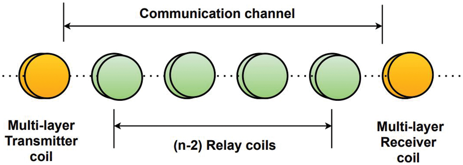
Figure 1: MI waveguide system model
The performance of a communication channel can be evaluated by the parameters like path loss, bandwidth, channel capacity, bit error rate and so on. Some of these parameters are considered herein for the performance analysis of MLC based MI waveguide system.
2.1.1 Path Loss of MI Waveguide Channel
In the considered MI waveguide structure, every adjacent pair of relay coils is separated by an inter-coil distance of r meters. If M represents the magnetic induction between two adjacent coils, ω is the angular frequency, then
where
To achieve low path loss, all the coils are designed to operate at resonating frequency f0, and thus the impedance of every coil is pure resistance (i.e., Z = R).
2.1.2 Bandwidth of MI Waveguide Channel
As all the coils are operating at resonant frequencies, the coil impedance is less and subsequently the bandwidth is also less. In this paper, 3-dB bandwidth B is considered as the channel bandwidth and thus the path loss at the frequency f0+ 0.5B will be twice at the central frequency f0, i.e., PL(f0+ 0.5B) = 2 x PL(f0). Substituting this in (1) gives
To derive an approximated expression of B, a low density of relay coils (relatively a larger inter-coil distance) is considered, which is economical and favorable for deployment. Consequently, the value of
The loaded capacitor C is designed for resonance condition to fulfill
2.1.3 Bit Error Rate of MI Waveguide Channel
In this paper, the 2PSK modulation technique is considered and according to that the BER is calculated as
Here, Pt, N0 represent transmitted power and receiver noise respectively [1].
In this section, various characteristics like coil resistance, self and mutual inductance of MLC are modeled.
In this paper, an orthogonal multilayered circular solid copper coil is considered. The coil has NT turns and NL layers as shown in Fig. 2. In this figure, an MLC is split into 4 equal quarters and the cross-sectional front view of a quarter is shown. Herein, Di, D0 represent the inner and outer diameters of the coil respectively. If R0 represents the unit length resistance of the copper winding, then coil resistance is given by R = Total length of winding ×R0 . The lengths of winding in layer 1, layer 2,…… layer NL are
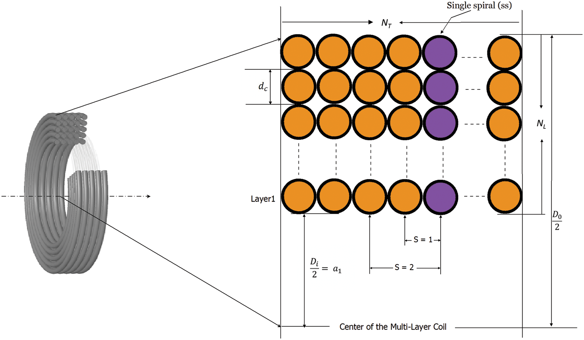
Figure 2: Cross-sectional front-view of one quarter of MLC
Hence, the length of entire copper winding is the aggregate of above lengths (sum of winding-lengths in all layers) =
The self-inductance of the MLC is modeled based on the method developed in [12,13]. Herein, the MLC is approximated as a combination of vertical single spirals attached together. According to this method, the equivalent inductance of an MLC can be calculated by
where,
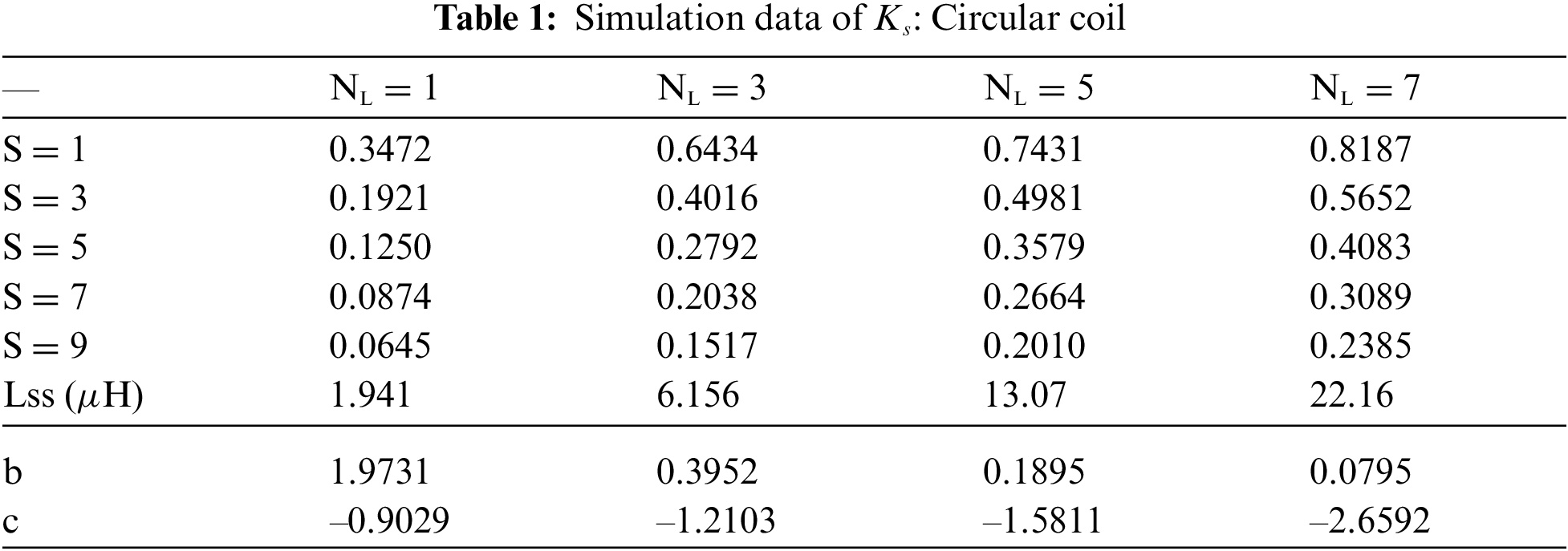
Here, Lss is the inductance of a single spiral. s is the normalized spacing between two single spirals. s = 1 implies the spacing between spirals is dc, s = 2 implies the spacing between spirals is 2 × dc and so on. ks is the coupling coefficient between s-spaced spirals. When s = 0, it is considered that ks = 1. Naturally as s increases, ks decreases. As the coupling coefficient value is related as 0 < ks < 1, it follows that b ≥ 0 and c < 0.
By substituting the value of ks in (2) and simplifying, the following equation is obtained.
As shown below, the values of b, c, Lss are modelled using Least Squares Method. The simulation data needed for this method is shown in Tab. 1.
3.3 Mutual Inductance between MLCs
The mutual inductance between two adjacent coils in calculated by
where ae is the effective coil radius given by
Here, µ, ϵ, σ are permeability, permittivity and conductivity of the medium respectively. By including this factor, the mutual inductance is finally transformed as
In this work, it is assumed that the coils are horizontally deployed (axes of the coils are collinear) and the orientation of coils is unchanged with time. Thus a maximum coupling is possible.
The performance of MLC based MI waveguide system (MLC-WG) is investigated in this section using MATLAB numerical analysis. Various parameters are considered to compare the MLC-WG performance with its SLC counterparts (SLC-WG). For the comparative analysis, the system parameters are taken from [1,10,25]. In this work, we considered three different media for performance comparison (viz., dry soil (ds), fresh water (fw) and wet soil (ws)). As MI channel has constant condition, the magnetic permeability in all these media is same as that of air i.e., µ0 = 4π × 10-7 H/m. The conductivities of the considered media are as follows; σds = 3 × 10⁻⁴ S/m, σws = 0.01 S/m, σf w = 3 × 10⁻³ S/m and the corresponding relative permittivities are ϵds = 7ϵ0, ϵws = 30ϵ0, ϵf w = 80ϵ0 respectively. The coil resistance is measured using the unit length resistance R0 = 0.01 Ω/m as per AWG 6 standard. The inner radius of the coil is
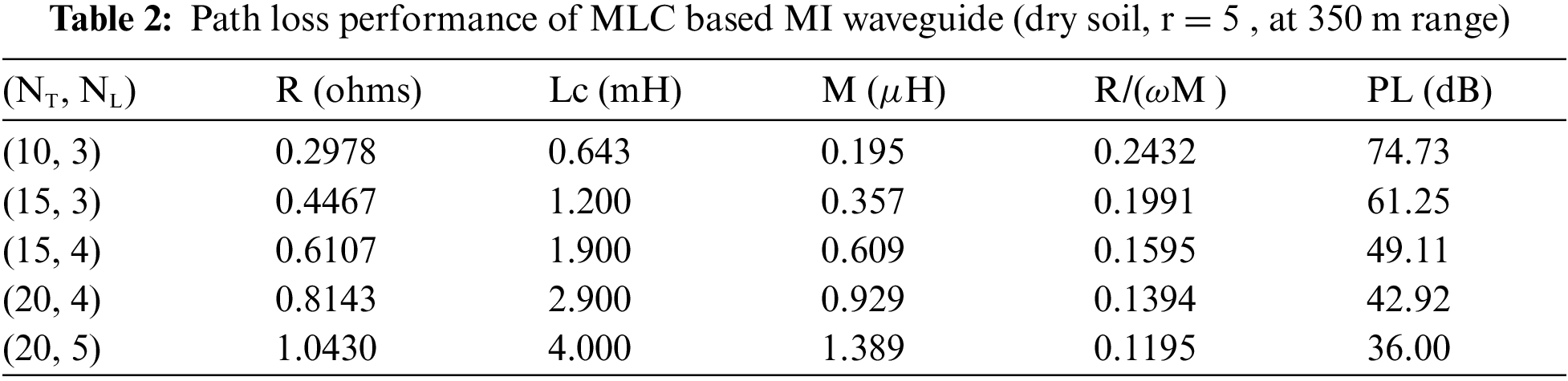
In Fig. 3, the path loss performance of SLC-WG and MLC-WG is comparatively shown. It can be seen that the path loss experienced in MLC-WG is lesser than that in SLC-WG. In MLCs, the addition of every layer results in an increase of both resistance and self-inductance. However, the path loss is decided by the combined effect of these two parameters based on the value of the ratio R/ωM. The path loss is directly proportional to this ratio [1]. As shown in Tab. 2, for the MLCs, as the number of turns and layers is increased, the coil self-inductance and resistance is also increased. Consequently, the mutual inductance between adjacent coils is increased, which facilitates a strong coupling between the relay coils. Thus, the path loss decreases in case of MLC-WG.
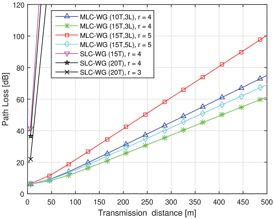
Figure 3: Comparison of path loss in SLC and MLC based MI waveguide system
In Fig. 4, the path loss performance is shown for different considered media. At a transmission distance of 310 m, the path loss of MI signal in dry soil, wet soil and fresh water media are 32 dB, 84 dB, 45 dB respectively. At any given transmission distance, it can be seen that the path loss experienced by the MI signal in dry soil medium is the least. This is due to the less conductivity of the dry soil medium, which results in relatively lesser signal attenuation.
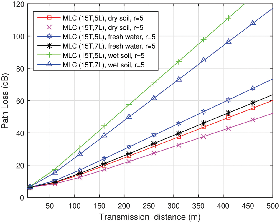
Figure 4: Path loss of MLC based MI waveguide system in various media
In Fig. 5, the BER characteristics of MLC-WG are compared with its single layer counterpart while varying the inter-coil distances. Herein, the transmission range of SLC-WG is around 30 m and this is due to high path loss experienced at 1 MHz frequency. Using MLCs, a higher transmission range is achieved. The transmission range is increased by around 15 times. It can also be noted here that even when r = 6, the MLC-WG system gives an impressive transmission range. Thus, MLCs can offer better range even in loosely coupled scenarios. In Fig. 6, the BER performance of MLC-WG is analyzed in different media. In accordance with the path loss performance, the BER performance is best observed in dry soil medium. Besides, we considered that the fresh water is in static situation and thus coil orientations are undisturbed. Thus the waveguide is performing better in fresh water medium than wet soil.
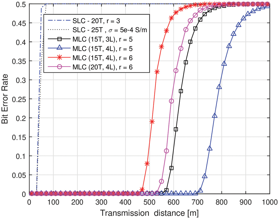
Figure 5: BER in SLC and MLC based MI waveguide systems
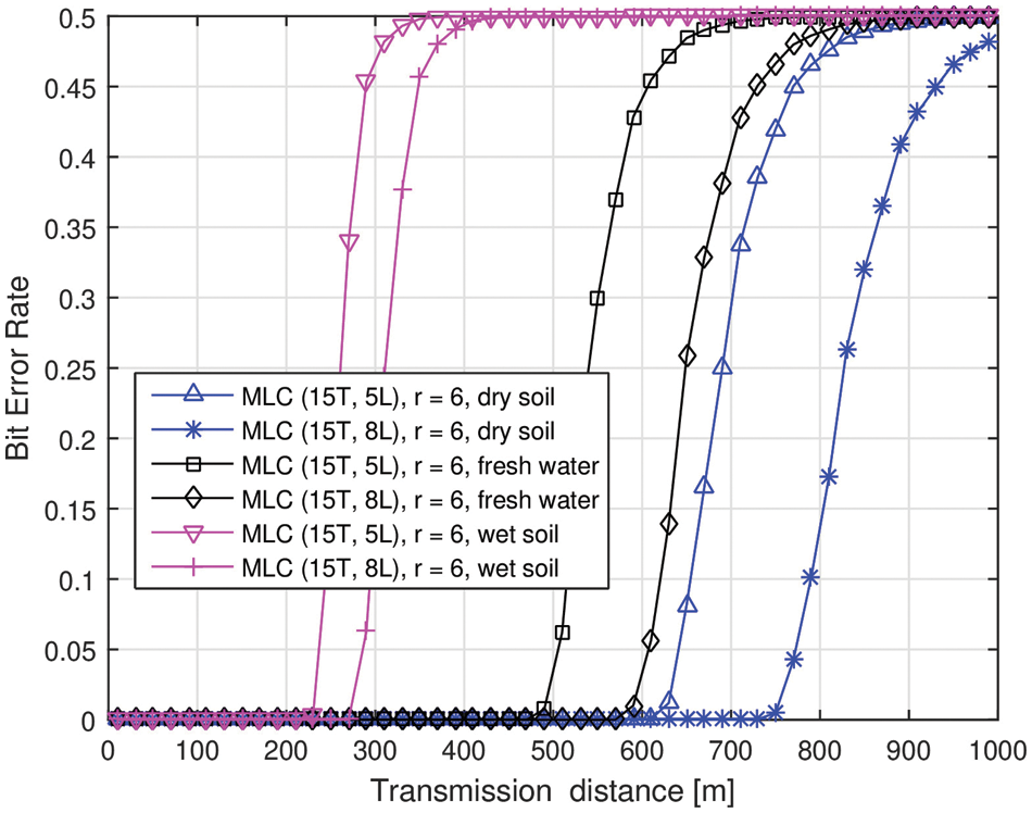
Figure 6: BER performance of MLC based MI waveguide system in various media
It is to be noted that, even though MLC-WG offers a better transmission range at the expense of material cost, the bandwidth is still less. In this work, it is observed to be less than 1KHz. This is a serious issue in some time-critical applications like border patrol and mine disaster rescue. Although the skin depth effect is considered in this work, additionally the proximity effect, parasitic capacitance will add to a little more resistance of the coil. Thus, a little degradation of performance can be expected. The parasitic capacitance of MLC is observed to be similar to that of SLC. More specifically, the value is in the same order and it differs by a few Pico Farads as shown in Tab. 3. Consequently, the capacitive reactance of the parasitic capacitance of both kinds of coils is in the same order of Mega ohms. Thus, the current that passes through the capacitive reactance element is very less. In other words, for both the coils, approximately the same amount of current passes through the parasitic capacitance element. Therefore, in this work, the effect of parasitic capacitance is not considered for comparative performance analysis. From [14], It is observed that, in MLCs, as the number of layers is increased, the parasitic capacitance decreases and it is lesser for smaller length coils (i.e., less number of turns).
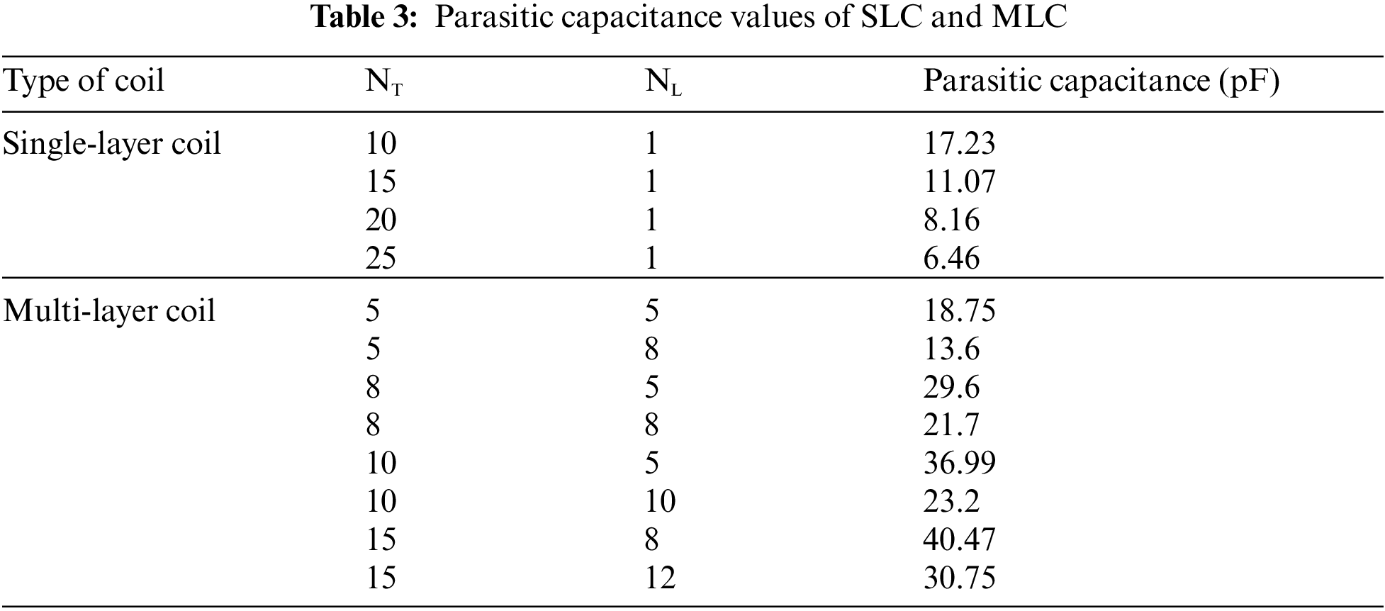
This behavior is opposite to that of SLCs, where the parasitic capacitance decreases with an increase of turns [10]. Nevertheless, the overall parasitic capacitance of MLCs is slightly greater than that of SLCs. It can be expected that the inclusion of parasitic capacitance in the path loss modelling reduces the overall system performance by using either of the coils. However, in case of MLCs, the self-inductance is 100 times greater than that of SLCs. Moreover, the resistance of the coil is very less as compared to the capacitive reactance of the coils. Thus, the performance of MLC-WG is better than that of SLC-WG system.
In this work, we investigated the performance of MI waveguide system using MLCs in three different non-conventional media. As compared with the single layer counterpart, the MLC waveguide system shows a significant decrease in path loss and a corresponding increase in the transmission range and bit error rate performance. Among the three considered media, the MI waveguide system performs better in dry soil medium due to the low conductivity of the medium. Remarkably, in the proposed MLC-WG system, the bandwidth is less than 1 KHz; which is smaller than SLC-WG, resulting in a low channel capacity. This can be enhanced by the spread resonance strategies and MIMO technique based solution proposed in [10,26]. Achieving a high channel capacity in addition to a large transmission range is still a challenging issue. This analysis is left for the future work.
Acknowledgement: This work is supported by Visvesvaraya PhD scheme under Ministry of Electronics and Information Technology (MEITY), India. The authors thank Dr. Santosh Sabat and Dr. Sunil Mutha for their generous contributions at different stages of the work.
Funding Statement: The authors received no specific funding for this study.
Conflicts of Interest: The authors declare that they have no conflicts of interest to report regarding the present study.
1. Z. Sun and I. F. Akyildiz, “Magnetic induction communications for wireless underground sensor networks,” IEEE Transactions on Antennas and Propagation, vol. 58, no. 7, pp. 2426–2435, 2010. [Google Scholar]
2. A. K. Sharma, S. Yadav, S. N. Dandu, V. Kumar, J. Sengupta et al., “Magnetic induction-based non-conventional media communications: A review,” IEEE Sensors Journal, vol. 17, pp. 926–940, 2016. [Google Scholar]
3. S. Yadav, V. Kumar, S. B. Dhok and D. N. Jayakody, “Energy-efficient design of MI communication-based 3-d non-conventional WSNs,” IEEE Systems Journal, vol. 14, no. 2, pp. 2585–2588, 2019. [Google Scholar]
4. S. Tambe, V. Kumar and R. Bhusari, “Magnetic induction based cluster optimization in non-conventional WSNs: A cross layer approach,” AEU-International Journal of Electronics and Communications, vol. 93, no. 4, pp. 53–62, 2018. [Google Scholar]
5. L. P. Akula, V. Kumar and S. B. Dhok, “Cooperative communication and energy-harvesting-enabled energy-efficient design of MI-based clustered non-conventional WSNs,” IEEE Systems Journal, vol. 14, pp. 2293–2302, 2019. [Google Scholar]
6. U. Raza and A. Salam, “A survey on subsurface signal propagation,” Smart Cities, vol. 3, no. 4, pp. 1513–1561, 2020. [Google Scholar]
7. R. Vyas and B. Tye, “A sequential RFID system for robust communication with underground carbon steel pipes in oil and gas applications,” Electronics, vol. 8, no. 12, pp. 1374, 2019. [Google Scholar]
8. Z. Sun and I. F. Akyildiz, “On capacity of magnetic induction-based wireless underground sensor networks,” in Proc. IEEE INFOCOM, Orlando, Florida, USA, pp. 370–378, 2012. [Google Scholar]
9. S. Kisseleff, W. Gerstacker, R. Schober, Z. Sun and I. F. Akyildiz, “Channel capacity of magnetic induction based wireless underground sensor networks under practical constraints,” in Proc. IEEE Wireless Communications and Networking Conf. (WCNC), Shanghai, China, pp. 2603–2608, 2013. [Google Scholar]
10. Z. Sun, I. F. Akyildiz, S. Kisseleff and W. Gerstacker, “Increasing the capacity of magnetic induction communications in RF-challenged environments,” IEEE Transactions on Communication, vol. 61, no. 9, pp. 3943–3952, 2013. [Google Scholar]
11. V. Kumar, R. Bhusari, S. B. Dhok, A. Prakash, R. Tripathi et al., “Design of magnetic induction based energy-efficient WSNs for non-conventional media using multilayer transmitter-enabled novel energy model,” IEEE Systems Journal, vol. 13, no. 2, pp. 1285–1296, 2018. [Google Scholar]
12. J. Kim, B. Kim, J. Kang and K. Kim, “A novel method for estimating multilayer coil inductance,” IEEE Magnetics Letters, vol. 8, pp. 1–4, 2017. [Google Scholar]
13. J. Kim, K. Kim, B. Kim and J. Kang, “Experimental validation of multi-layer coil inductance estimation method,” in Proc. IEEE Int. Sym. on Antennas and Propagation & USNC/URSI National Radio Science Meeting, San Diego, California, USA, pp. 1303–1304, 2017. [Google Scholar]
14. B. Wu, X. Zhang, X. Liu and C. He, “An analytical model for predicting the self-capacitance of multi-layer circular-section induction coils,” IEEE Transactions on Magnetics, vol. 54, no. 11, pp. 1–7, 2018. [Google Scholar]
15. I. Mahariq, K. Hamza and K. Mustafa, “Questioning degree of accuracy offered by the spectral element method in computational electromagnetics,” The Applied Computational Electromagnetics Society Journal (ACES), vol. 30, no. 7, pp. 698–705, 2015. [Google Scholar]
16. I. Mahariq and A. Erciyas, “A spectral element method for the solution of magnetostatic fields,” Turkish Journal of Electrical Engineering & Computer Sciences, vol. 25, no. 4, pp. 2922–2932, 2017. [Google Scholar]
17. I. Mahariq, H. I. Tarman and M. Kuzuoğlu, “On the accuracy of spectral element method in electromagnetic scattering problems,” International Journal of Computer Theory and Engineering, vol. 6, no. 6, pp. 495–499, 2014. [Google Scholar]
18. I. Mahariq, “On the application of the spectral element method in electromagnetic problems involving domain decomposition,” Turkish Journal of Electrical Engineering & Computer Sciences, vol. 25, no. 2, pp. 1059–1069, 2017. [Google Scholar]
19. I. Mahariq and H. Kurt, “Strong field enhancement of resonance modes in dielectric microcylinders,” Journal of the Optical Society of America B (JOSAB), vol. 33, no. 4, pp. 656–662, 2016. [Google Scholar]
20. I. Mahariq, I. H. Giden, H. Kurt, O. V. Minin and I. V. Minin, “Strong electromagnetic field localization near the surface of hemicylindrical particles,” Optical and Quantum Electronics, vol. 50, no. 11, pp. 1–8, 2018. [Google Scholar]
21. I. Mahariq, M. Kuzuoğlu and I. H. Tarman, “On the attenuation of the perfectly matched layer in electromagnetic scattering problems with the spectral element method,” Applied Computational Electromagnetics Society Journal, vol. 29, no. 9, pp. 701–710, 2014. [Google Scholar]
22. I. Mahariq, M. Kuzuoğlu, I. H. Tarman and H. Kurt, “Photonic nanojet analysis by spectral element method,” IEEE Photonics Journal, vol. 6, no. 5, pp. 1–14, 2014. [Google Scholar]
23. S. Alabed, I. Mahariq, M. Salman and M. Kuzuoğlu, “A novel beamforming emulating photonic nanojets for wireless relay networks,” Computers, Materials and Continua, vol. 69, no. 1, pp. 575–588, 2021. [Google Scholar]
24. S. Kisseleff, I. F. Akyildiz and W. H. Gerstacker, “Throughput of the magnetic induction based wireless underground sensor networks: Key optimization techniques,” IEEE Transactions on Communications, vol. 62, no. 12, pp. 4426–4439, 2014. [Google Scholar]
25. R. ITU, “Electrical characteristics of the surface of the earth,” ITU-R P. 527-6, 2021. [Online]. Available: https://www.itu.int/dms_pubrec/itu-r/rec/p/R-REC-P.527-6-202109-I!!PDF-E.pdf. [Google Scholar]
26. H. J. Kim, J. Park, K. S. Oh, J. P. Choi, J. E. Jang et al., “Near-field magnetic induction MIMO communication using a heterogeneous multipole loop antenna array for higher data rate transmission,” IEEE Transactions on Antennas and Propagation, vol. 64, no. 5, pp. 1952–1962, 2016. [Google Scholar]
From (4),
Assuming that X =
The above expression forms a quadratic equation in X given by
The roots of the above quadratic equation are given by
where t1 and t2 refer to the corresponding L.H.S terms.
It can be observed in the roots that
Now, as
i.e.,
Re-substituting the value of
where P = n-1.
 | This work is licensed under a Creative Commons Attribution 4.0 International License, which permits unrestricted use, distribution, and reproduction in any medium, provided the original work is properly cited. |