DOI:10.32604/cmc.2022.026654
| Computers, Materials & Continua DOI:10.32604/cmc.2022.026654 | |
| Article |
A Dynamic Multi-ary Query Tree Protocol for Passive RFID Anti-collision
1Centre for RFIC and System, School of Information and Communication Engineering, University of Electronic Science and Technology of China, Chengdu, 611731, P.R.China
2Nanjing University of Information Science & Technology, Nanjing, 210044, China
3Queen Mary University of London, London, United Kingdom
*Corresponding Author: Daniele Inserra. Email: inserradaniele@uestc.edu.cn
Received: 31 December 2021; Accepted: 01 March 2022
Abstract: In this paper, a dynamic multi-ary query tree (DMQT) anti-collision protocol for Radio Frequency Identification (RFID) systems is proposed for large scale passive RFID tag identification. The proposed DMQT protocol is based on an iterative process between the reader and tags which identifies the position of collision bits through map commands and dynamically encodes them to optimize slots allocation through query commands. In this way, the DMQT completely eliminates empty slots and greatly reduces collision slots, which in turn reduces the identification time and energy costs. In addition and differently to other known protocols, the DMQT does not need to estimate the number of tags, reducing the protocol implementation complexity and eliminating the uncertainty caused by the estimation algorithm. A numerical analysis shows that DMQT has better performance than other algorithms for a number of tags larger than 300. Meanwhile, when the number of tags is 2000 and the tag identity (ID) length is 128 bits, the total identification time is 2.58 s and the average energy cost for a tag identification is 1.2 mJ, which are 16.9% and 10.4% less than those of state-of-the-art algorithms, respectively. In addition, a DMQT extension based on ACK command has also been presented to deal with capture effect and avoid missing identification.
Keywords: Anti-collision; DMQT; RFID; dynamic multi-ary query; seamless identification
RFID is attracting a lot of attention from both academic research and industrial environment not only because of historical field of applications like assets management and tracking [1] or indoor localization [2,3], but also for other new potential usages like the implementation of tag-sensors for environmental monitoring [4,5]. Furthermore, RFID has been recognized as one of the key technology for the implementation of Internet of Things (IoT) and Internet of Everythings (IoE) paradigms [6]. In this context where a multitude of RFID tags are simultaneously connected, it is fundamental to develop anti-collision algorithms specifically designed for RFID; in fact, general multiple access algorithms cannot be applied for RFID due to the limited hardware equipment of tags, especially the passive ones.
The existing anti-collision algorithms are mainly based on Aloha (where the medium access mechanism is random) and tree (based on deterministic search mechanisms) schemes, and many variants have been proposed during the years (Pure Aloha (PA) [7], Slotted Aloha (SA) [8], Framed Slotted Aloha (FSA) [9], Dynamic Frame Slotted Aloha (DFSA) [10], etc., and Query tree (QT) [11], Tree Splitting (TS) [12] Binary Search (BS) [13], Bitwise arbitration (BTA) [14], etc.). Clearly, if tree anti-collision algorithms are properly designed, they can offer superior efficiency than other non-deterministic methodologies.
In QT protocols, the reader probes different ID prefixes (starting from one bit and then iteratively concatenating all the others) to identify all the tags population. In Binary QT protocol, only the most significant bit (MSB) of the collided ID part is used, therefore it generates a large number of collision slots and empty slots during the identification process [15]. For this reason, some Multi-ary QT protocols (which probe tag IDs with multiple M bits simultaneously) have been proposed to improve the system’s identification performance. For this reason, some Multi-ary QT protocols (which probe tag IDs with multiple M bits simultaneously) have been proposed to improve the system’s identification performance. [16] proposes a time- and energy-aware protocol based on M-ary collision tree (MCT) for efficient RFID tag identification, the M is a fixed value, and this may cause many idle slots when M is too large, or several collision slots when M is too small, making difficult to find an optimum performance, [17] is similar to [16] in that it has fixed M value. [18] proposed a bit query algorithm based on Multi-ary query tree (BQMT) protocol to eliminate empty slots. However, the algorithm requires to estimate the number of tags of non-idle nodes, which increases the uncertainty and complexity. In [19], authors proposed an adaptive assigned tree slotted Aloha (AdATSA) protocol, which again needs to estimate the number of tags, and its maximum efficiency is only 61.7%. In [20], Self-learning Smart Trend-Traversal (STT) protocol dynamically changes the length and the value of query prefix, which increases the number of empty slots and, therefore, resulting in a longer identification time. In [21], a collision window tree (CwT) protocol used to transmits W bits instead of the whole ID (0 < W < K (K is the bit width of ID)), which causes more time slots than other QT-based protocols, resulting in a longer identification time.
In this paper, a dynamic multi-ary query tree (DMQT) protocol for passive RFID anti-collision is proposed. Differently from [16–18] which use a fixed M value, the proposed DMQT exploits a dynamic multi-ary tree structure to eliminate the number of empty slots with the consequent minimization of the identification time and required tag energy, and it does not require any number of tags estimation algorithm as in [18,19], avoiding estimation uncertainties and the consequent identification time stretching. Moreover, it employs multi-ary Map command to reduce the transmission overhead similarly to [21], which further reduces the identification time.
The main contribution of this paper can be summarized as follows:
1. A DMQT protocol which uses Map command to identify collision bits quantity and position and dynamically group certain portions of tags to minimize the collision probability, and Query command to complete the identification of the grouped tags. The dynamic selection of M and the Map/Query mechanism is fundamental to eliminate empty slots and minimize collision slots, with the consequent reduction of the identification time.
2. The DMQT does not rely on any number of tags estimation algorithm, therefore greatly reducing the implementation complexity if compared with [18] (which requires such estimation process), and eliminating the uncertainty caused by the estimation algorithm (which in many cases increase the identification time).
3. An extensive numerical analysis is performed to benchmark the performance of the proposed DMQT and compare it with other existing algorithms, confirming the validity of the proposed algorithm. Moreover, a simple algorithm extension is proposed for coping with the capture effect, whose performance is also numerically verified.
2 Preliminaries: Bit Tracking and ID Query
In this paper, we mainly focus on large RFID systems, i.e., the identification of a large number of passive tags. Readers have no prior knowledge of the distribution of tags around them (they do not know the number of tags and their ID information), and adopt the reader-talk-first model to work. Tags respond to commands issued by readers. As the number of tags in RFID system may reach thousands to tens of thousands and all tags share the same communication channel, tag collisions easily happen which increases the collision time slot and identification time. How to quickly identify a large number of tags is a big challenge for RFID system [22–27].
In RFID systems, Manchester encoding is often used to identify collision information. Manchester Encoding is a line code, in which every bit of data will have a transition in the middle of the data bit after coding [28]. In general, the transition from high to low level (down edge) in the middle of the data represents data 1, and the transition from low to high level (up edge) represents data 0. If the receiver receives two tags returning different information at the same time, this will cause the rising edge and falling edge to cancel each other, resulting in the appearance of an illegal symbol, which the receiver can consider as a collision [29]. As shown in Fig. 1, it is assumed that the IDs of the two tags are “10101101” and “11101011”, respectively.
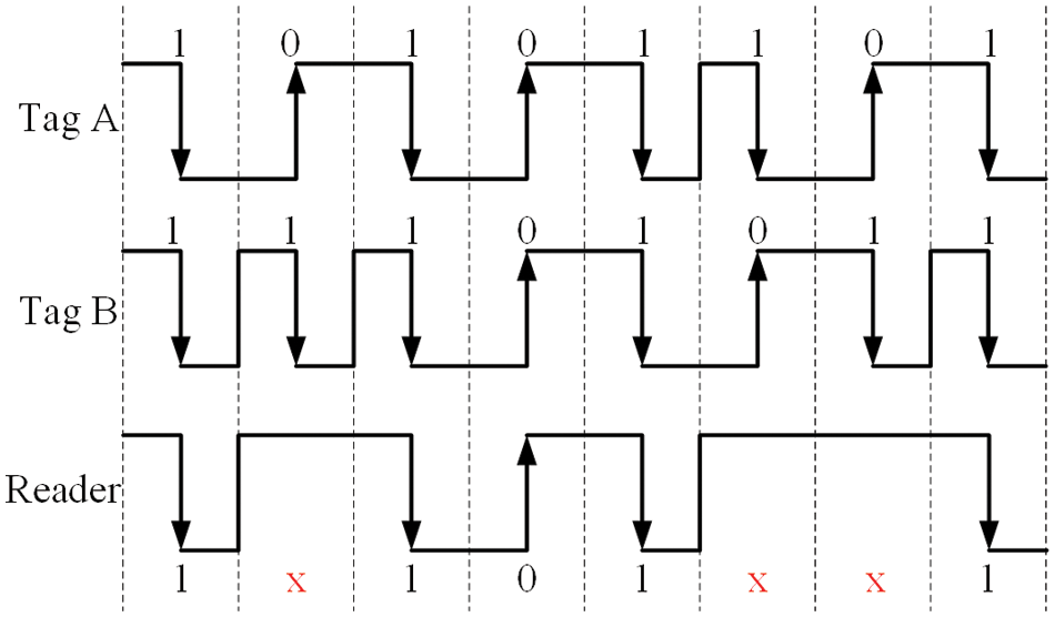
Figure 1: Manchester coding
The ID of the two tags is encoded using Manchester code, and sent to the receiver at the same time, resulting in the received code “1x101xx1”, where “x” represents the collision bit. As a result, the receiver can detect collisions with 3 bits of data. The receiver can estimate the number of tags around it according to the collision information and some tag number estimation algorithms, thus improving the identification efficiency of RFID system [30]. Finally, due to the very low modulation signal rate of the tag and the commands issued by the reader, bit-wise synchronization of tag responses is assumed [18,31,32].
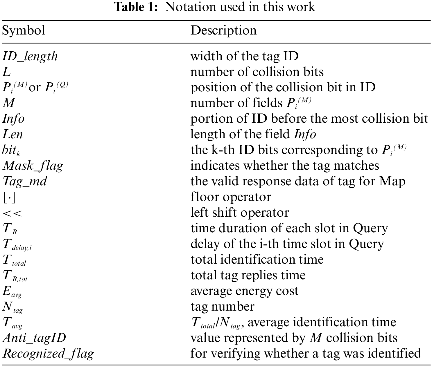
For the sake of a better comprehension and to make the paper more readable, Tab. 1 summarizes the notation employed in this work.
The proposed DMQT protocol is composed of a multi-ary Map command and a Multi-tags query command. The Map command is used to sound the distribution of collision bits, while the Query identifies tags and/or obtains collision information. Fig. 2 describes the timing logic of DMQT. Except for the first Map command (M = 0), there is a one-to-one correspondence between Map commands and Query commands. The Map command can obtain ID distribution of matched tags, and then perform targeted group identification in Query to eliminate empty slots. The DMQT can continuously identify multiple tags or obtain collision information of multiple groups of tags using Query, reducing the identification time and power consumption. Where TM is the time when the reader sends the Map command, T1 is the tag response time, T2 is the reader response time, T3 is the tag response interval in the adjacent sub-slots in Query command, TR is the duration of the tag response signal, and ‘reps’ is the response of tag.
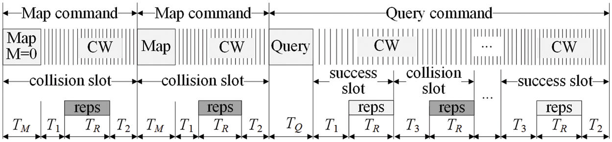
Figure 2: DMQT algorithm timing
As shown in Fig. 2, the DMQT algorithm has no empty slots, and only the success slots and collision slots. The Query command has multiple sub-slots. The sub-slots are the success slots without collision, and the sub-slots are the collision slots with collision.
The proposed DMQT protocol is based on a “map and query” iteration process. A Map command is firstly executed to locate the collision bits, select one portion of these bits, and identify the number of collided bit patterns, while the query command is employed to splits the tag ID patterns into different slots. This operation is executed iteratively until no collisions are identified within slots. The length of the collided patterns and the number of slots is updated dynamically to minimize the required identification time. The DMQT identification process is shown in Fig. 3, where the number of tags
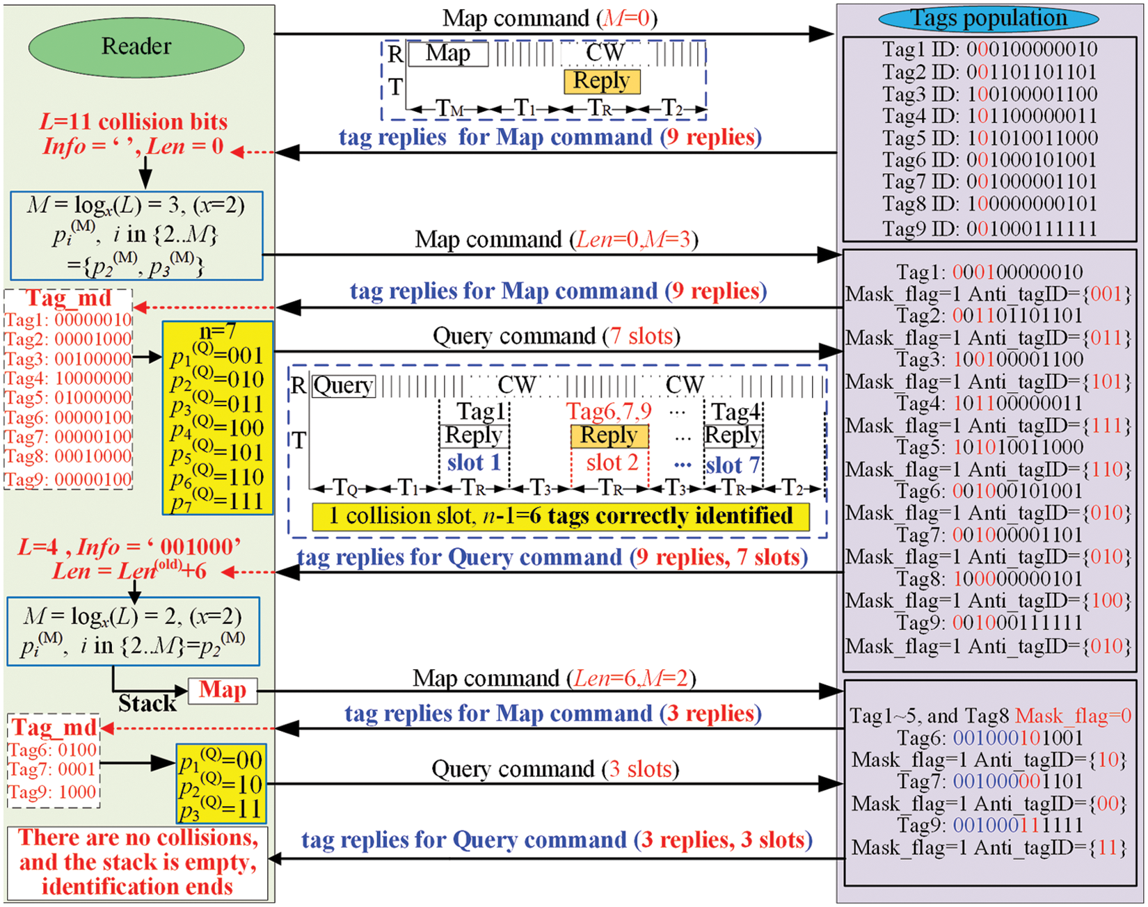
Figure 3: Proposed DMQT protocol
The structure of the Map command (simply Map in the follows) is shown in Tab. 2. The field Len indicates the length of the field Info which is the portion of ID before the most significant collision bit; M indicates the number of fields
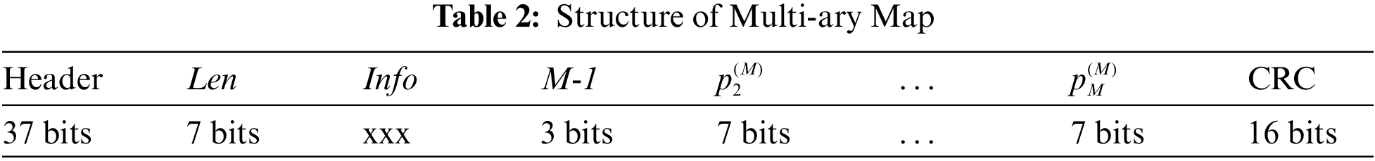
At the beginning, the reader sends a Map with M = 0 and waits for tag response. When the reader receives the tag response, it determines the new M value and all the other fields required to generate the new Map, which is then sent to tags. the new M value as
Here, the L indicates the number of collision bits received by the reader (the maximum value is the length of tag ID, ID_length), and
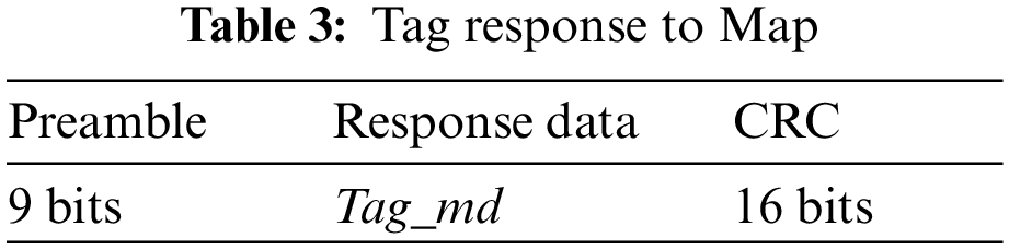
The structure of tag replies to Map is instead depicted in Tab. 3. When a tag receives a Map, it checks whether its Len most significant bits (MSB) of ID match Info; in this case, it sets Mask_flag = ‘1’, Anti_tagID = {bit1,bit2,…, bitM}, and Tag_md as
It is worth noting that for each tag only one bit of (2) will be ‘1’, and its position within Tag_md will be the correspondent decimal value of
When reader receives the N tag replies, it checks the number of collision bits of Tag_md, n, and their positions,
and (ii) the number of replied different Anti_tagID patterns n. It is worth noting that n ≤ N because more than one tag may share the same Anti_tagID pattern, and these tag IDs will be discriminated successively.
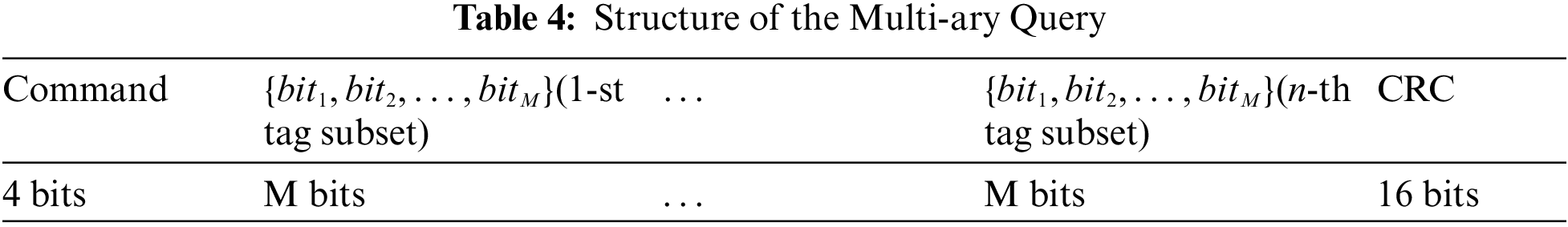
The structure of the query command (simply Query in the follows) is shown in Tab. 4. The Query divides the Map matched tags into n subsets corresponding to n slots, ordered according to
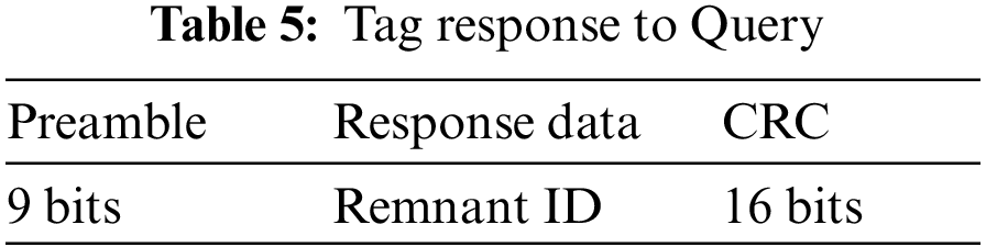
When a tag receives the Query, it firstly checks whether Mask_flag = ‘1’ and, if not, it stays silent; otherwise, the tag (i) locates its correspondent reply slot within Query, i.e., the subset with
Note that since the tag responds to the remnant ID, the generated Info must include the Info from the previous Map command. The new Info is as follows:
Here, Info(old) comes from the previous Map command, and Info(rem) is generated based on the remnant ID. In the same way, the newly Len should be added the Len(old) from the Map command:
Here,
The time duration of each slot will be
Therefore, the i-th slot will be delayed by
The reader can calculate the total time of executing the Query command as:
The reader calculates the execution time required by Query according to Eq. (8). When the Query is completed, the reader will pop a Map from the stack executing the Map-Query process until the stack is empty, and updating the Len value at each step as the previous Len plus the length of the new Info field.
A numerical analysis of the average and total identification time and average energy cost of the proposed DMQT protocol is now presented (simulations have been carried out according to parameters listed in Tab. 6).
The average energy consumption has been introduced in [16] by estimating the total reader energy required for performing the identification of a tag population, divided by the number of tags under the assumption of constant power (only the RF signal transmission required energy has been taken into account which is the largest energy contribution [33]). During the identification process (of duration
Eq. (9) shows that it is not only important to reduce
As it can be seen,
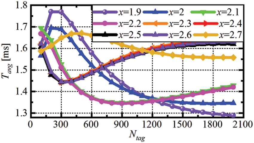
Figure 4: Comparison of the proposed DMQT simulations results for different x values for average identification time
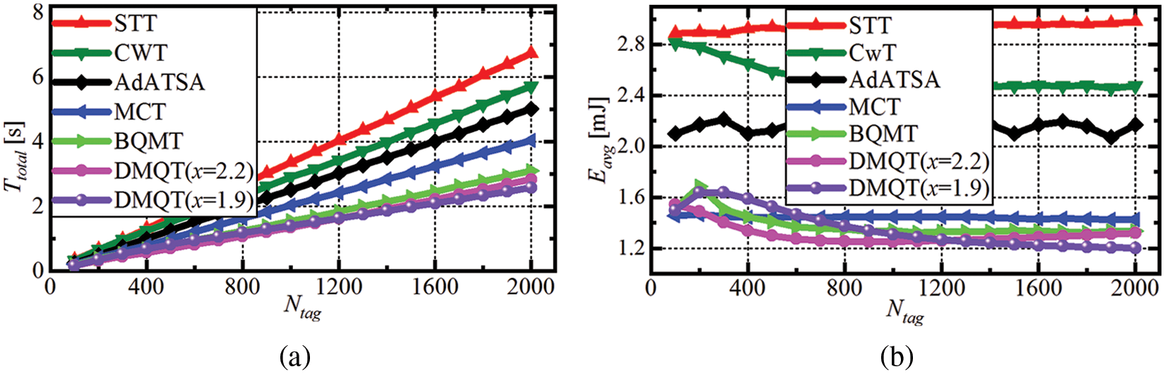
Figure 5: Comparison of DMQT simulation results with other referred algorithms. (a) Total identification time, and (b) Average energy costs
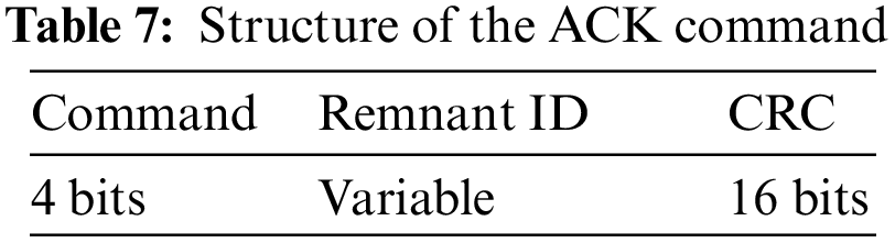
In a passive RFID system, when multiple tags reply to the reader simultaneously, it is possible that one tag’s signal is much stronger than other signals, leading to the so-called capture effect [34]. If the capture effect occurs, the original collision slot will be turned into a singleton slot, which accelerates the identification process [17]. However, the capture effect may cause missing identification [34–38]. Although the most part of the published papers ignore the capture effect [33,39–41], in order to improve the robustness of the DMQT algorithm, this effect shall be considered. When the capture effect exists, it may be possible that some tags uninterruptedly reply to the reader’s inventory disturbing the communication with weak signal tags (seamless identification phenomenon). Therefore, DMQT can be optimized by adding a response mechanism based on the ACK command to avoid the replies of tags already identified, i.e., when the reader recognizes one tag, it sends an ACK command. When receiving an ACK command, the identified tag enters the identification state and does not respond to subsequent identification commands. At the same time, when the reader detects that the stack is empty, it continues a new identification process until there is no tag response in the new identification process. The format of the ACK command is shown in Tab. 7, it does not require the tag to return a response signal.
When receiving an ACK command, the tag matching Remnant ID sets Recognized_flag = 1, then the tag will not respond to the reader identification command. In order to ensure that the reader and tag can correctly generate and process ACK command, some improvements should be made to DMQT Query timing to meet the requirements of the reader and tag processing timing. The timing logic of Query after adding ACK command is shown in Fig. 6. Before adding an ACK, the tag does not need to care about whether the sub-slot is a collision slot or not, and only needs to return the response information in the allocated sub-slot. However, the timing logic adding ACK differs from Fig. 2. In fact, the fixed T3 cannot be used as the guard time between two continuous sub-slots. Here, T2 is still used to represent the time between the end of the tag response and the ACK sent by the reader, and T3 is replaced by T4 (1.5T2) to ensure that the reader has enough time to generate the ACK command.
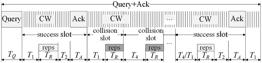
Figure 6: Query timing logic with ACK command
Since the ACK does not occur in every slot, the tag must be delayed according to the time slot status. The matching tag (Mask_flag = 1) will record the number of successful time slots
Therefore, after the Ack is added, the delay time of the i-th sub-slot of the Query is:
According to Fig. 6, the reader can calculate the total time of executing Query as:
After adding an ACK, the identified tag enters the identification state. If no further processing is performed, the tag in the identification state may not respond to subsequent identification commands. To improve system reliability, the tag must be removed from the identification state under the control of the reader. This function can be achieved through different combinations of M and Len values in the Map. Its combined functions are shown in Tab. 8. To prevent tag missing identification under capture effect, DMQT will continue to send a “seamless identification” command when the stack is empty, that is, send Map (M = 0, Len = 1) for a new identification round. If the reader does not receive any reply after sending the seamless identification, the identification process is complete.
The need of the ACK command makes the identification longer, also because more than one inventory is necessary to identify all tags (in fact, stronger signal tags are initially identified during the first inventory round, and weaker signal tags are identified in successive inventories). Performance of the proposed modified DMQT in the presence of the capture effect has been simulated similarly to [17], and results are shown Fig. 7 (p is herein used to represent the probability of capture effect occurrence).
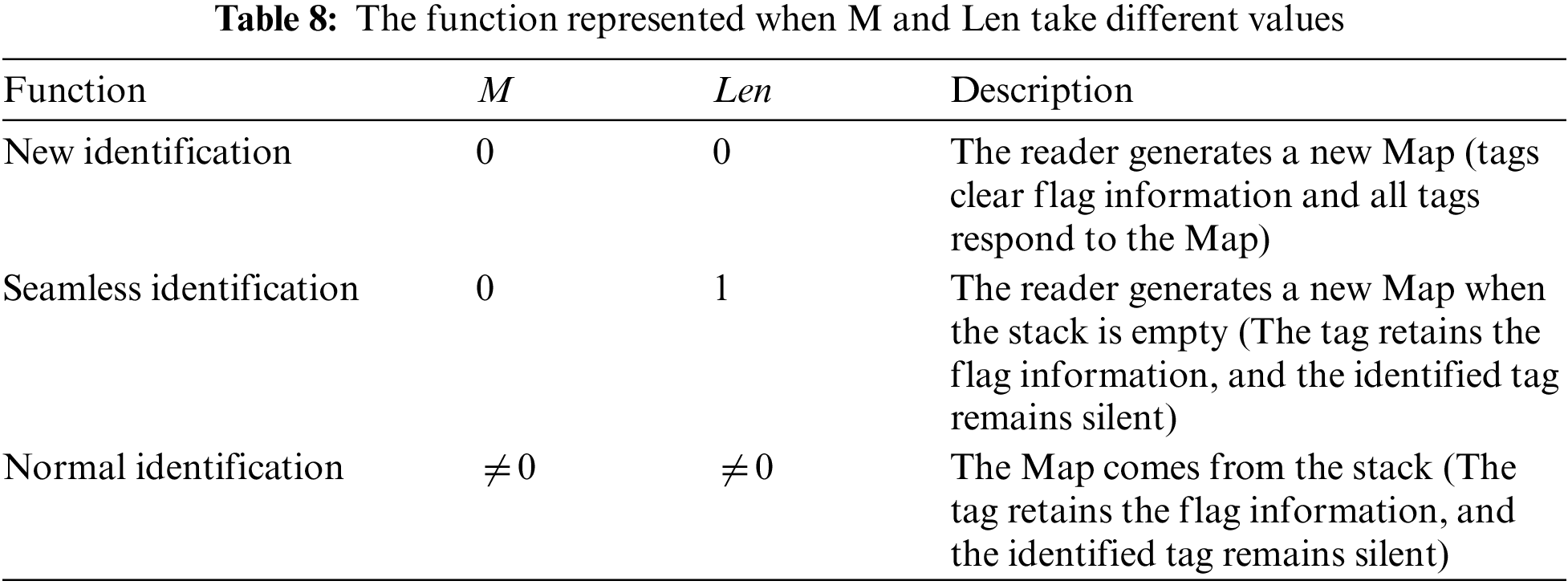
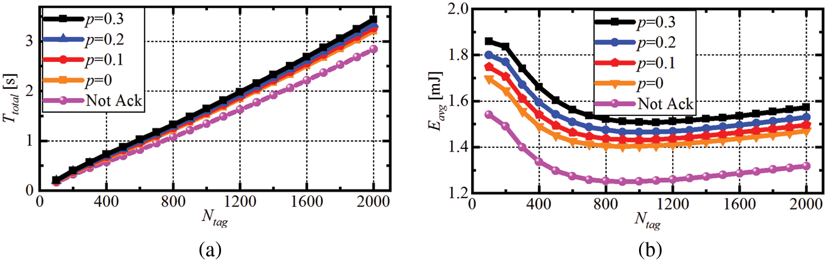
Figure 7: Modified DMQT simulation results for different capture effect probabilities
As it can be seen,
This paper presents a dynamic multi-ary query tree collision protocol for RFID systems which can completely eliminate empty slots and greatly reduce collision slots. The proposed scheme is based on an iterative process between reader and tags which aims at locating all collision bits and dynamically encoding them to optimize slots allocation, which reduces the identification time and energy costs. Particularly, simulation results have revealed that the total identification time and the average energy costs are less than 2.58 s and 1.2 mJ, respectively, when the number of tags is from 300 to 2000, both lower than those of other existing algorithms, making the DMQT protocol very suitable for improving the anti-collision state-of-the-art performance of passive RFID systems. Finally, the DMQT is extended with the use of ACK command to cope with the capture effect, showing excellent identification performance.
Funding Statement: The authors received funding for this study from the National Key R&D Program (https://chinainnovationfunding.eu/national-key-rd-programmes/), project contract No. 2018YFB1802102 (G.W.) and 2018AAA0103203 (W.T, F.X, G.W.), from the National Natural Science Foundation of China (https://www.nsfc.gov.cn/), project contracts No. 61971113 (G.W.) and 61901095 (D.I.), from the Guangdong Provincial Research and Development Plan in Key Areas (https://chinainnovationfunding.eu/funding-programmes-guangdong-province-2/), project contracts No. 2019B010141001 (G.W.) and 2019B010142001 (G.W.), from the Sichuan Provincial Science and Technology Planning Program (https://www.sc.gov.cn/10462/10758/10759/10763/2010/10/28/10147629.shtml), project contracts No. 2020YFG0039 (G.W.), 2021YFG0013 (G.W.), and 2021YFH0133 (D.I.), from the Ministry of Education (http://en.moe.gov.cn/) and China Mobile (http://www.chinamobileltd.com) Joint Fund Program, project contract No. MCM20180104 (G.W., G.L.), and from the fundamental research funds for the Central Universities (managed by Department of Finance, https://www.fmprc.gov.cn/mfa_eng/wjb_663304/zzjg_663340/cws_665320/), project contract no. YGX2019Z022 (G.W., G. L., D. I.).
Conflicts of Interest: The authors of this paper declare that there are no conflicts of interest regarding the publication of this paper.
1. J. Choo and J. Ryoo, “UHF RFID tag applicable to various objects,” IEEE Transactions on Antennas and Propagation, vol. 62, no. 2, pp. 922–925, 2014. [Google Scholar]
2. P. Prusaczyk, L. Baranowski and J. Panasiuk, “Vehicle navigation systems involving inertial sensors and odometry data from on-board diagnostics in non-gps applications,” Technical Sciences, vol. 22, no. 3, pp. 263–270, 2020. [Google Scholar]
3. A. Athalye, V. Savic, M. Bolic and P. M. Djuric, “Novel semi-passive RFID system for indoor localization,” IEEE Sensors Journal, vol. 13, no. 2, pp. 528–537, 2013. [Google Scholar]
4. K. W. Nowak, “Identification of meat types by ultrasonic methods,” Technical Sciences, vol. 18, no. 2, pp. 79–84, 2015. [Google Scholar]
5. X. Wang, J. Zhang, Z. Yu, S. Mao, S. C. G. Periaswamy et al., “On remote temperature sensing using commercial UHF RFID tags,” IEEE Internet of Things Journal, vol. 6, no. 6, pp. 10715–10727, 2019. [Google Scholar]
6. S. S. Anjum, R. M. Noor, M. H. Anisi, I. B. Ahmedy, F. Othman et al., “Energy management in RFID-Sensor networks: Taxonomy and challenges,” IEEE Internet of Things Journal, vol. 6, no. 1, pp. 250–266, 2019. [Google Scholar]
7. D. K. Klair, K. Chin and R. Raad, “A survey and tutorial of RFID anti-collision protocols,” IEEE Communications Surveys & Tutorials, vol. 12, no. 3, pp. 400–421, 2010. [Google Scholar]
8. D. K. Klair, K. Chin and R. Raad, “An investigation into the energy efficiency of pure and slotted Aloha based RFID anti-collision protocols,” in Proc. IEEE WOWMOM, Espoo, Finland, pp. 1–4, 2007. [Google Scholar]
9. B. Zhen, M. Kobayashi and M. Shimizu, “Framed aloha for multiple RFID objects identification,” IEICE TRANSACTIONS on Communications, vol. E88-B, no. 3, pp. 991–999, 2005. [Google Scholar]
10. W. T. Chen and G. H. Lin, “An efficient anti-collision method for tag identification in a RFID System,” IEICE TRANSACTIONS on Communications, vol. E89-B, no. 12, pp. 3386–3392, 2006. [Google Scholar]
11. L. Zhang, J. Zhang and X. Tang, “Assigned tree slotted aloha RFID tag anti-collision protocols,” IEEE Transactions on Wireless Communications, vol. 12, no. 11, pp. 5493–5505, 2013. [Google Scholar]
12. H. Guo, C. He, N. Wang and M. Bolic, “PSR: A novel high-efficiency and easy-to-implement parallel algorithm for anticollision in RFID systems,” IEEE Transactions on Industrial Informatics, vol. 12, no. 3, pp. 1134–1145, 2016. [Google Scholar]
13. S. Yu, Y. Zhan, Z. Wang and Z. Tang, “Anti-collision algorithm based on jumping and dynamic searching and its analysis,” Computer Engineering, vol. 31, no. 9, pp. 19–20, 2005. [Google Scholar]
14. S. H. Kim and P. Park, “An efficient tree-based tag anti-collision protocol for RFID systems,” IEEE Communications Letters, vol. 11, no. 5, pp. 449–451, 2007. [Google Scholar]
15. X. Jia, Q. Feng and L. Yu, “Stability analysis of an efficient anticollision protocol for RFID tag identification,” IEEE Transactions on Communications, vol. 60, no. 8, pp. 2285–2294, 2012. [Google Scholar]
16. L. Zhang, W. Xiang, X. Tang, Q. Li and Q. Yan, “A time- and energy-aware collision tree protocol for efficient large-scale RFID tag identification,” IEEE Transactions on Industrial Informatics, vol. 14, no. 6, pp. 2406–2417, 2018. [Google Scholar]
17. J. Shin, B. Jeon and D. Yang, “Multiple RFID tags identification with M-ary query tree scheme,” IEEE Communications Letters, vol. 17, no. 3, pp. 604–607, 2013. [Google Scholar]
18. J. Su, Y. Chen, Z. Sheng, Z. Huang and A. X. Liu, “From M-ary query to bit query: A new strategy for efficient large-scale RFID identification,” IEEE Transactions on Communications, vol. 68, no. 4, pp. 2381–2393, 2020. [Google Scholar]
19. L. Zhang, W. Xiang and X. Tang, “An adaptive anti-collision protocol for large-scale RFID tag identification,” IEEE Wireless Communications Letters, vol. 3, no. 6, pp. 601–604, 2014. [Google Scholar]
20. L. Pan and H. Wu, “Smart trend-traversal protocol for RFID tag arbitration,” IEEE Transactions on Wireless Communications, vol. 10, no. 11, pp. 3565–3569, 2011. [Google Scholar]
21. H. Landaluce, A. Perallos, E. Onieva, L. Arjona and L. Bengtsson, “An energy and identification time decreasing procedure for memoryless RFID tag anticollision protocols,” IEEE Transactions on Wireless Communications, vol. 15, no. 6, pp. 4234–4247, 2016. [Google Scholar]
22. C. N. Yang and J. Y. He, “An effective 16-bit random number aided query tree algorithm for RFID tag anti-collision,” IEEE Communications Letters, vol. 15, no. 5, pp. 539–541, 2011. [Google Scholar]
23. W. Sung and S. Hsiao, “RFID positioning and physiological signals for remote medical care,” Computer Systems Science and Engineering, vol. 41, no. 1, pp. 289–304, 2022. [Google Scholar]
24. A. Abugabah, L. Sanzogni, L. Houghton, A. A. AlZubi and A. Abuqabbeh, “RFID adaption in healthcare organizations: an integrative framework,” Computers Materials & Continua, vol. 70, no. 1, pp. 1335–1348, 2022. [Google Scholar]
25. J. Su, Z. Sheng, A. Liu, Z. Fu and Y. Chen, “A time and energy saving based frame adjustment strategy (TES-FAS) tag identification algorithm for UHF RFID systems,” IEEE Transactions on Wireless Communications, vol. 19, no. 5, pp. 2974–2986, 2020. [Google Scholar]
26. C. Wang, X. Shao, Y. Meng and J. Gao, “A physical layer network coding based tag anti-collision algorithm for RFID system,” Computers Materials & Continua, vol. 66, no. 1, pp. 931–945, 2021. [Google Scholar]
27. C. N. Yang and J. Y. He, “An effective 16-bit random number aided query tree algorithm for RFID tag anti-collision,” IEEE Communications Letters, vol. 15, no. 5, pp. 539–541, 2011. [Google Scholar]
28. Y. Mu, R. Ni, Y. Sun, T. Zhang, J. Li et al., “A novel hybrid tag identification protocol for large-scale rfid systems,” Computers Materials & Continua, vol. 68, no. 2, pp. 2515–2527, 2021. [Google Scholar]
29. D. Zhang, X. Wang, X. Song and D. Zhao, “A novel approach to mapped correlation of ID for RFID anti-collision,” IEEE Transactions on Services Computing, vol. 7, no. 4, pp. 741–748, 2014. [Google Scholar]
30. Y. Lai, L. Hsiao, H. Chen, C. Lai and J. Lin, “A novel query tree protocol with bit tracking in RFID tag identification,” IEEE Transactions on Mobile Computing, vol. 12, no. 10, pp. 2063–2075, 2013. [Google Scholar]
31. C. Angerer and M. Rupp, “Advanced synchronisation and decoding in RFID reader receivers,” in Proc. IEEE Radio and Wireless Symp., San Diego, CA, USA, pp. 59–62, 2009. [Google Scholar]
32. J. Su, Z. Sheng, A. X. Liu, Y. Han and Y. Chen, “Capture-aware identification of mobile RFID tags with unreliable channels,” IEEE Transactions on Mobile Computing, vol. 21, no. 4, pp. 1182–1195, 2022. [Google Scholar]
33. V. Namboodiri and L. Gao, “Energy-aware tag anticollision protocols for RFID systems,” IEEE Transactions on Mobile Computing, vol. 9, no. 1, pp. 44–59, 2010. [Google Scholar]
34. H. Wu and Y. Zeng, “Passive RFID tag anticollision algorithm for capture effect,” IEEE Sensors Journal, vol. 15, no. 1, pp. 218–226, 2015. [Google Scholar]
35. W. J. Shin and J. G. Kim, “A capture-aware access control method for enhanced RFID anti-collision performance,” IEEE Communications Letters, vol. 13, no. 5, pp. 354–356, 2009. [Google Scholar]
36. Y. Maguire and R. Pappu, “An optimal Q-algorithm for the ISO 18000-6C RFID protocol,” IEEE Transactions on Automation Science and Engineering, vol. 6, no. 1, pp. 16–24, 2009. [Google Scholar]
37. J. S. Garcia and D. R. Smith, “Capture probability in rician fading channels with power control in the transmitters,” IEEE Transactions on Communications, vol. 50, no. 12, pp. 1889–1891, 2002. [Google Scholar]
38. D. J. Goodman and A. A. M. Saleh, “The near/far effect in local ALOHA radio communications,” IEEE Transactions on Vehicular Technology, vol. 36, no. 1, pp. 19–27, 1987. [Google Scholar]
39. Y. C. Lai, L. Y. Hsiao, H. J. Chen, C. N. Lai and J. W. Lin, “A novel query tree protocol with bit tracking in RFID tag identification,” IEEE Transactions on Mobile Computing, vol. 12, no. 10, pp. 2063–2075, 2013. [Google Scholar]
40. J. V. Alonso, V. B. Delgado, E. E. Lopez, F. J. G. Castano and J. Alcaraz, “Multiframe maximum-likelihood tag estimation for RFID anticollision protocols,” IEEE Transactions on Industrial Informatics, vol. 7, no. 3, pp. 487–496, 2011. [Google Scholar]
41. L. Zhang, W. Xiang and X. Tang, “An efficient bit-detecting protocol for continuous tag recognition in mobile RFID systems,” IEEE Transactions on Mobile Computing, vol. 17, no. 3, pp. 503–516, 2018. [Google Scholar]
 | This work is licensed under a Creative Commons Attribution 4.0 International License, which permits unrestricted use, distribution, and reproduction in any medium, provided the original work is properly cited. |