DOI:10.32604/cmc.2022.028165
| Computers, Materials & Continua DOI:10.32604/cmc.2022.028165 | |
| Article |
Improved Dijkstra Algorithm for Mobile Robot Path Planning and Obstacle Avoidance
1Department of Mechanical Engineering, College of Engineering, University of Ha’il, Ha’il, 2440, Saudi Arabia
2Department of Computer and Network Engineering, College of Computer Science and Engineering, University of Jeddah, Jeddah, 21959, Saudi Arabia
3Research Laboratory of Metrology and Energy Systems, National Engineering School, Energy Engineering Department, University of Monastir, Monastir, 5000, Tunisia
*Corresponding Author: Sahbi Boubaker. Email: sboubaker@uj.edu.sa
Received: 04 February 2022; Accepted: 22 March 2022
Abstract: Optimal path planning avoiding obstacles is among the most attractive applications of mobile robots (MRs) in both research and education. In this paper, an optimal collision-free algorithm is designed and implemented practically based on an improved Dijkstra algorithm. To achieve this research objectives, first, the MR obstacle-free environment is modeled as a diagraph including nodes, edges and weights. Second, Dijkstra algorithm is used offline to generate the shortest path driving the MR from a starting point to a target point. During its movement, the robot should follow the previously obtained path and stop at each node to test if there is an obstacle between the current node and the immediately following node. For this aim, the MR was equipped with an ultrasonic sensor used as obstacle detector. If an obstacle is found, the MR updates its diagraph by excluding the corresponding node. Then, Dijkstra algorithm runs on the modified diagraph. This procedure is repeated until reaching the target point. To verify the efficiency of the proposed approach, a simulation was carried out on a hand-made MR and an environment including 9 nodes, 19 edges and 2 obstacles. The obtained optimal path avoiding obstacles has been transferred into motion control and implemented practically using line tracking sensors. This study has shown that the improved Dijkstra algorithm can efficiently solve optimal path planning in environments including obstacles and that STEAM-based MRs are efficient cost-effective tools to practically implement the designed algorithm.
Keywords: Mobile robot (MR); STEAM; path planning; obstacle avoidance; improved dijkstra algorithm
In the current 21st century, robots are occupying a key place in several domains including industry, agriculture, healthcare, construction, logistics and education… In education, extensive works have focused on implementing Science, Technology, Engineering, Art and Mathematics (STEAM) approaches around mobile robots (MRs). With the integration of modern technologies such as 3D printing, open-source programming environments, artificial intelligence (AI) and Internet of Things (IoT) in the fourth industrial revolution 4.0 context, MRs are playing constructive roles. Due to their capability of locomotion and ability to interact with their close environments, MRs (controlled or autonomous) can be used in education and research. MRs are inherently multidisciplinary systems involving several disciplines ranging from material engineering to cognitive science and computer vision. Concepts like kinematics, 3D printing, mechanical design and material science belong to the Mechanical Engineering (ME). In addition, an MR should include motors, sensors, controllers, power electronics and batteries which are concepts related to Electrical Engineering (EE). Computer Engineering (CE) and Computer Science (CS) may be present in a MR through programming and more attractively through modern applications such as path planning, computer vision, wireless sensor networks, communication, artificial intelligence. Purchasing “professional” mobile robotics platforms is unfortunately expensive for a relatively limited use (as low as 1%) as reported by [1]. To overcome this difficulty, many researchers resorted to design their own DIY (Do-It-Yourself) platforms under various technical (should be based on open resources), educational (can be used to implement various educational activities), cost (should be affordable) and efficiency (should perform several tasks) considerations.
In this paper, the progressive steps of a STEAM framework around an MR are detailed. A particular attention is allocated to the components in order to make it as easy as possible to be implemented by students at different levels. In addition, the problem of path planning and obstacle avoidance is addressed from its algorithmic and motion control perspectives. The flow-chart of the work conducted in this study is presented in Fig. 1.
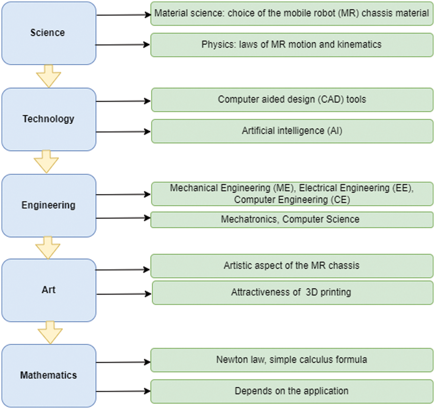
Figure 1: Flow-chart of a STEAM framework based on a mobile robot (MR)
The main contributions of the current study can be highlighted as follows:
• Implement a STEAM framework around an MR in a simple and detailed manner in order to make it easy to be conducted from scratch by students, educators and researchers.
• Show the multi-disciplinarity of MRs and how they can be used to assess skills in different disciplines.
• Address the problem of path planning and obstacle avoidance of the DIY MR using an efficient and computationally low-cost algorithm (an improved Dijkstra algorithm).
• Show how the shortest path solution derived from the algorithm is transferred into control motion and implemented practically.
The remainder of this paper is described as follows. In Section 2, a relatively detailed state-of-the-art of previously developed mobile robotics platforms is presented as well as selected researches about path planning. Section 3 will include the robot design and the steps of the STEAM framework. In Section 4, a path planning and obstacle avoidance application of the designed mobile robot will be presented. Section 5 concludes the paper.
During the last few years, many researches about mobile robotics platforms have been conducted from STEAM perspective. These researches were different according to several factors. In this section, selected platforms will be described according to many features including the year of implementation, the mechanical design tool, the cost, the used sensors, the programming tool, the application and the achieved skills. A special focus will be allocated to the path planning and its relevant components. Mona robotics platform has been developed in The University of Manchester, UK [1] in 2019. This platform is mainly based on open-source programmable devices, low-cost and including several sensors. Among the advantages of this platform is that it allows robots communication which strengthens the concept of swarm of robots largely used in research and education. The concept of swarm (group of interacting) mobile robots has been also addressed in [2] where the authors have developed an interface allowing full integration of robots in the ROS (Robotics Operating System). Through the novel driver interface, mobile robotics practitioners may focus more on their tasks which can include data manipulation, robots’ communication and sensors deployment. For teaching some concepts of science (the pulsimeter), robotic and coding (programming) tools have been used in a middle school in Turkey (2018-2019) [3]. Via a structured approach, students have developed their own experiments using the open-access Arduino platform. Small printable robots (called “printbots”) have been presented in [4] as strong educational tools for studying mobile robots and manipulators. The usefulness of these robots took benefit from the availability of 3D printers. Several courses have been designed (practice and simulation) over 8 years in a Spanish institute. The concept of deep learning (as extension of machine learning) is the trend of nowadays research in computer science and engineering. A real need of experimental platforms to easily conduct deep learning projects has motivated the authors in [5] to implement an affordable robotics platform around the well-known Arduino board. The main advantage of this platform is that it includes a mobile phone for capturing photos and videos which can be then easily handled in several integrated development environments (IDEs) such as Python, Matlab and C/C++.
When participating in a European robotics contest, the team of [6] has faced technical issues in their robots, 3 days before the beginning. Thus, they had resort to open hardware and software resources as well as to smartphones and cloud services to carry out “fast” prototypes which have later achieved 83% of required tasks of the competition. In 2015, a Spanish team has designed a low-cost (around 35 Euro) robotics platform using Arduino and Android mobile operating system to be used in various courses covering information technology, communication and engineering [7]. Similar to the work presented in [4], the authors in [8] have designed low-cost robots using the 3D printing technology and have conducted 3 educational experiments with students. Several concepts including design, sensoring and programming have been successfully taught. During the European robotics week (2018), the work developed in a workshop for teaching STEM concepts has been described in detail in [9]. Although the participants had no previous experience in programming and mathematics, the main objectives of the workshop have been reported (by the authors) to be achieved. Developing countries such as Mexico are missing practical and hands-on tools to teach robotics in elementary and university schools which may result on decrease in motivation. To overcome this difficulty, the authors in [10] have used a hexapod robot to assess the programming skills. The achieved results were reported to be excellent. In the same direction, the authors in [11] have built a robotics platform only for 25 USD (2018) to implement a line-follower application where several skills related to sensors, Bluetooth communication and microcontrollers’ programming have been improved in a STEM framework. More successful STEM implementations using robotics platforms can be found in [12–27]. Although these studies are distributed over different periods and were designed using different tools and resources, they all led to results promoting the capability of thinking as well as improving 21st century skills.
Path planning of mobile robots includes the algorithms and the resulting control motion strategies that allows the MR to move in its close environment following the shortest path and avoiding collision [28]. In their survey paper [29], the authors have provided a summary of the algorithms used for path planning. They reported that Dijkstra’s algorithm remains among the best ones. The concept of neural dynamics has been used in [30] for solving the path planning problem of an autonomous robot moving in an unknown dynamic environment. From a control perspective, [31] has developed a switching control law for obstacle avoidance of a MR. The practical implementation has been shown to be without heavy computational effort nor a high memory requirement. A hardware platform and a software algorithm have been developed in [32] for a car system. Dijkstra’s algorithm has been successfully applied for path planning and obstacle avoidance in a generated unknown indoor environment. Offline path planning algorithms have been used to generate data for training a neural network algorithm used online for path planning [33]. Although the results were reported to be promising, the time-consuming character of neural networks were considered as a limitation. Other researches have tackled the path planning of MRs using Q-learning algorithm [34] and a combination of Dijkstra and A* algorithms [35]. As compared to the state-of-the-art algorithms for path planning, the improved Dijkstra algorithm has shown its superiority at least in three levels. Firstly, Dijkstra algorithm is simple in its structure because it works on any environment as modeled by the designer from the beginning without adding any nodes like in [28] where extra nodes are included. In fact, adding nodes may induce extra computational burden. Secondly, the Dijkstra algorithm has the ability to find the optimal path from a starting node to any other node in the graph including the target node defined by the user. Its computational complexity is known to be O(n2) where n is the number of nodes in the diagraph. This complexity is stated in [29] to be better than the complexity of A* algorithm for example. Finally, our proposed improved Dijkstra algorithm is shown through this study to operate in a dynamic environment in which even moving obstacles can be detected and the MR can react to update its path accordingly without any additional computation time.
From the previous literature review, it can be noticed that:
• Mobile robots (MRs) are efficient systems around which STEAM framework can be implemented for achieving several skills in education and conducting successful researches.
• Path planning from both algorithmic and hardware perspectives can be practically implemented using the STEAM designed MR.
• Dijkstra’s algorithm remains among the best algorithms for MR path planning.
3 STEAM Methodology Implementation
In this work, the progressive steps of designing and manufacturing a low-cost robotics platform to be used in education and research are detailed. The process follows a science, technology, engineering, art and mathematics (STEAM) approach. At each step, the component related to STEAM is clarified. The designed platform use free access resources in order to reduce the cost and make the design affordable by students and researchers particularly in developing countries where resources are relatively limited.
3.1 Mobile Robot Chassis Design
As an immediate consequence of the emergence of 3D printers, students and researchers can take benefit from this new technology to develop their own robotics platforms. However, the software side remains challenging because commercial (professional) software is still relatively expensive. As opposite to several platforms which require paid licenses, we chose a relatively new platform, Tinkercad (a product from Autodesk Company), known to be online and free1. This platform includes several tools that can help in 3D design, electric/electronic circuits, code-block programming and many free courses and tutorials. Moreover, this platform allows the user to create his personal account and keep all his previous designs and circuits in cloud storage. In this work, Tinkercad is used for two tasks: the mechanical design and the programming of the microcontroller during the simulation step.
In Tinkercad, the mechanical design is based on the principle of constructive solid geometry (CSG) where basic shapes and on adding/removing other shapes to construct complex forms are used. A screenshot of a simple mobile robotics platform customized for conducting this work is shown in Fig. 2.
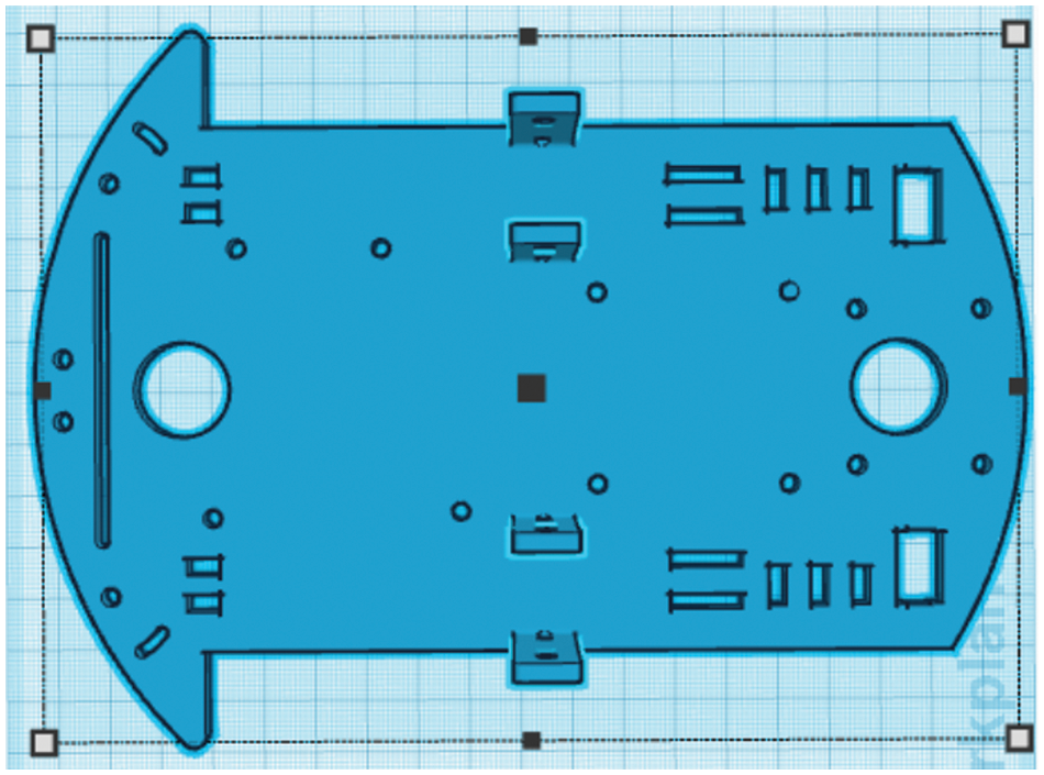
Figure 2: Screenshot of Tinkercad-based design of the mobile robot
In this study, the MR platform has been designed to be functional, low-cost, and extendable to other applications [27]. The following parts have been assembled to construct the MR:
• Wheels: two standard wheels in addition to a castor wheel in order to provide to the MR stability and sufficient traction [24].
• Motors: two direct current (DC) motors to operate the MR.
• Motors’ driver: to control the MR motion.
• Microcontroller: to generate the control signals applied to the driver as well as to receive the sensors’ signals.
• Battery: to provide the energy to the MR.
• Sensors: to serve as perception tools for the MR close environment.
The material used to construct the MR can be plastic, MDF (medium density fiber), acrylic or metal frame. In order to reduce the cost, in this study, the choice was a chassis fabricated using plastic material.
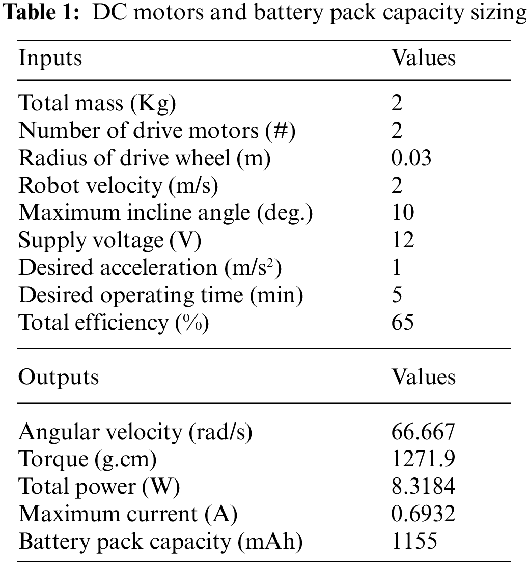
To select the driven motors and the battery pack capacity, an online motor sizing tool was used2. For a mobile robot, direct current (DC) motors are commonly used. However, those motors have the drawback of turning very fast without generating sufficient torque. The solution usually adopted consists of reducing the speed (
Since the MR will move in a flat surface, the torque will be calculated following Eq. (2) below.
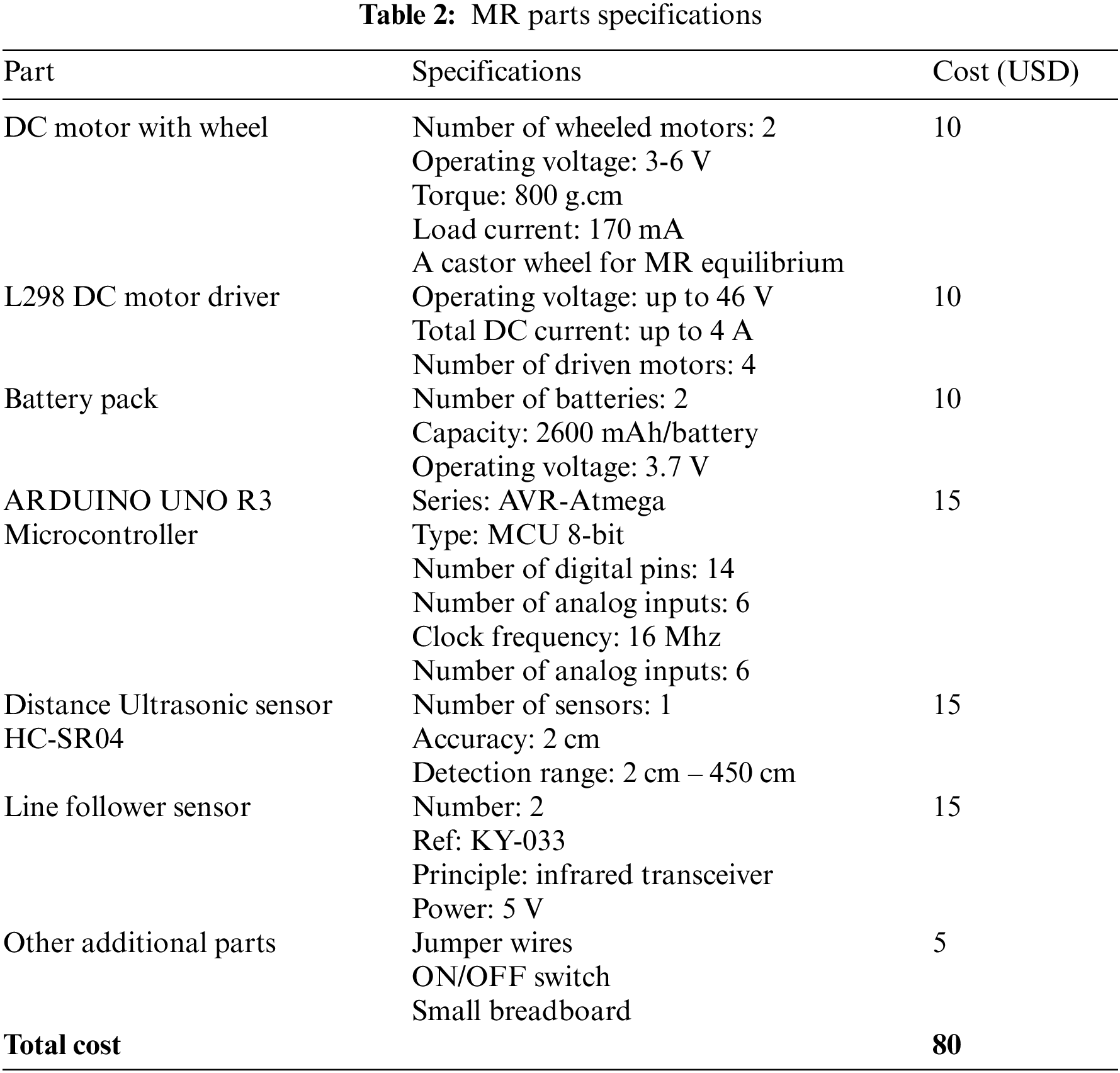
The safety factor is used here to allow the battery pack to power the MR embedded electronics such as the microcontroller and the sensors. Moreover, some imperfections in the surface will be overcome by the MR. The results provided by the sizing motor tool are summarized in Tab. 1. Based on the results of Tab. 1, the corresponding selected MR system parts as well as their technical specifications are provided in Tab. 2. In order to implement the path planning applications, an ultrasonic sensor and two infrared line following sensors have been also included to the MR platform.
DC Motor Driver
The L298N module has the following pinouts:
• Two terminal screwed power pins for each one of the two motors. These pins provide the voltage for driving the motors. The motors used in the MR require a voltage between 7 and 12 V.
• One terminal screwed pin for the Ground.
• A 5 V pin used for control signals’ generation.
• Two Enable pins (ENA and ENB) used in general for controlling the motors speeds. This will be done through a jumper. If the jumper exists, the motors work at their maximum speeds and if it is removed, the Pulse Width Modulation (PWM) input is activated and thus the motors speeds can be controlled.
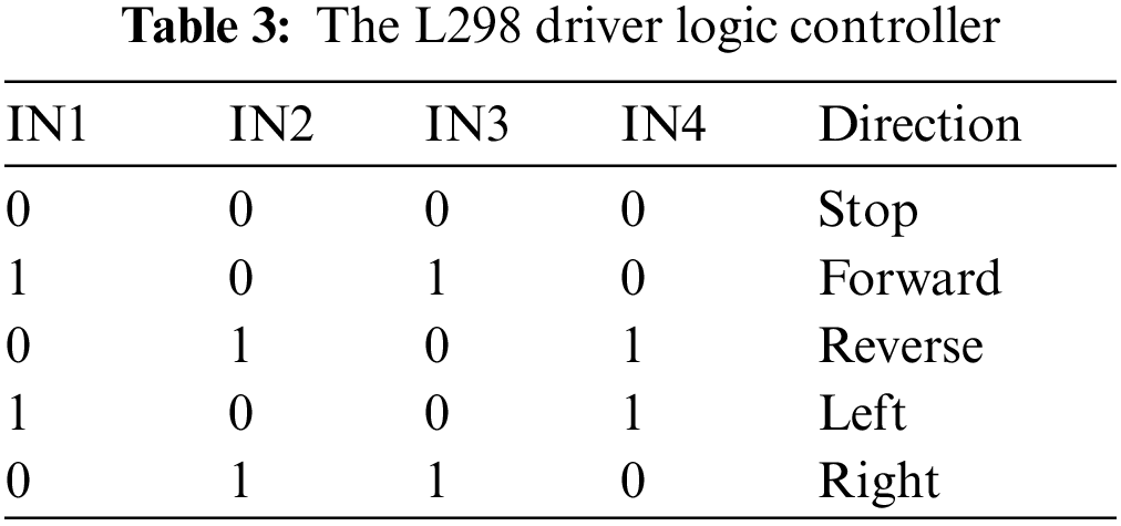
• The pins IN1, IN2, IN3 and IN4 are used for controlling the motors directions and for stopping them. Note here that (IN1, IN2) are used for one motor and (IN3, IN4) are used for the other motor.
Since the robot can move Reverse, Forward, Left, Right and Stop, the corresponding combinations of the IN1, IN2, IN3 and IN4 states are summarized in Tab. 3.
Ultrasonic Sensor
The ultrasonic sensor (HC-SR04) is an electronic device able to measure the distance to the first object existing in front of it. It is based on the same principle of radar and sonar. In fact, the sensor source generates an ultra-high frequency signal which is reflected after hitting the obstacle. The reflected echo is sensed by the sensor receiver. The microcontroller measures the duration between sending the signal and receiving the echo and then calculates the distance using the formula:
The speed of the ultrasonic wave is known to be 343 m/s.
Line Follower Sensor
Line follower sensor (KY-033) is a sensor that gives the mobile robot the ability to detect colored (white/light-black/dark) lines or surfaces. The sensor working operation is based on detecting reflected light being emitted by its infrared transmitter [20]. By measuring the amount of reflected infrared light, it can detect transitions from light to dark (lines) or even objects directly in front of it. If a HIGH value is received, the surface/line is dark/black and if the received value is LOW, the surface/line is light/white. This principle will be used later for following the optimal path derived from the path planning and obstacle avoidance algorithm using two line-follower sensors.
4 Path Planning and Obstacle Avoidance
4.1 Obstacle-free Path Planning Based on Dijkstra Algorithm
In this section, a path planning and obstacle avoidance algorithm is designed and its output transferred to a global motion planning for the MR [29]. Path planning is known to be among hard-to-solve problems since its main purpose is to generate an optimal path driving the MR from a starting point to a target point in an environment known a priori [28]. The path planning problem solution can be either global (when the problem is solved offline before starting the MR mission) or local (when the environment is sensed while the robot is moving alongside its trajectory). The arrival of new information may contribute to update the optimal path. Dijkstra’s algorithm has shown high competitiveness when compared to similar algorithms such as A* and its variants. Due to its usefulness, it has been adopted in many applications such as Google Maps [29]. Dijkstra’s algorithm (as a global algorithm) has been combined to a dynamic window used as a local path planning algorithm in an unknown indoor environment [30] such as for logistics applications. In this paper, an approach using Dijkstra algorithm, first, in a global level and then, iteratively in a local level is designed, evaluated and tested on a real DIY MR. The key idea is to generate a global optimal path. During the MR motion, information received from an ultrasonic sensor (used as an obstacle detector) will serve to update the robot trajectory in order to avoid collision.
In this work, a MR is assumed to move inside its environment including obstacles. A path planning solution is the optimal sequence of movements that drive the MR from a starting point to a target point while following the shortest path and avoiding obstacles. The MR close environment is modeled using graph theory as a diagraph
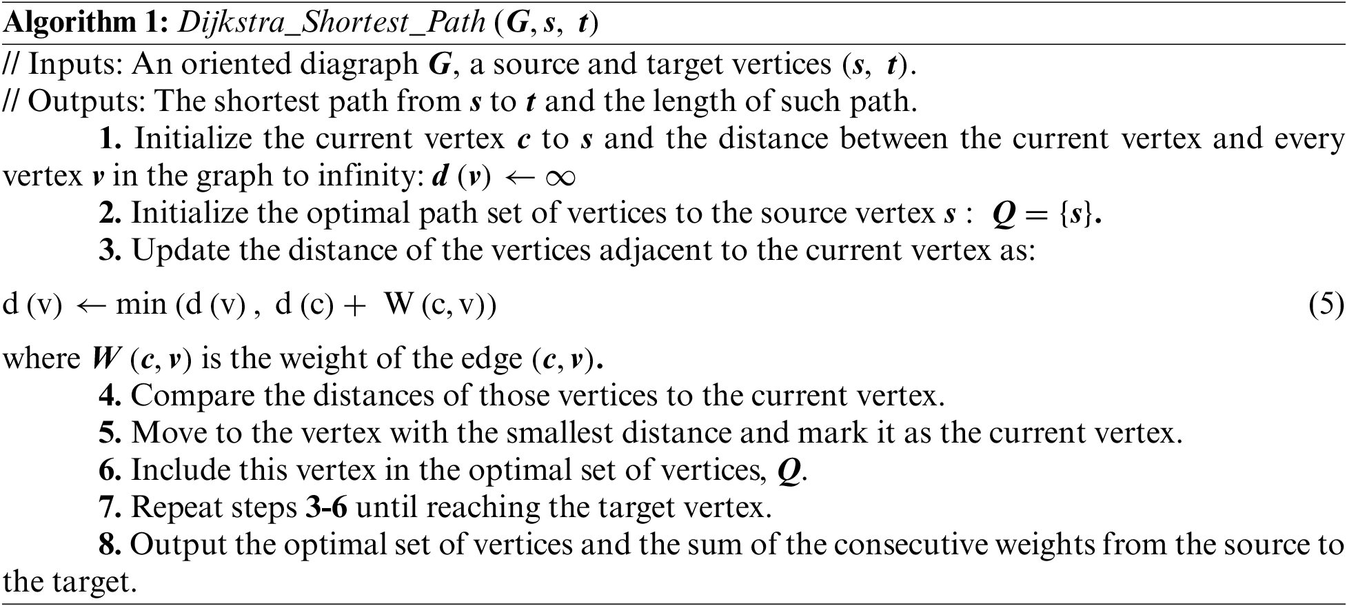
Among the efficient algorithms previously used for solving problem 1, Dijkstra’s algorithm is adopted in this paper. The main concept of this algorithm is to construct a set of vertices starting at the source vertex and ending at the target vertex such that the sum of edges’ weights (called distances) is minimal. Problem 1 is posed as follows.
Problem 1: Shortest path in an obstacle-free digraph
Find the sub-graph
The steps of this algorithm are presented as follows.
4.2 Path Planning with Obstacle Avoidance
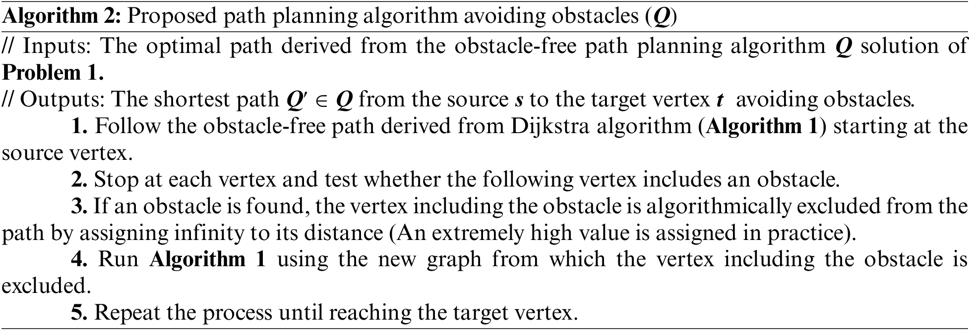
If the environment of the MR modeled as a diagraph includes obstacles, the path planning avoiding obstacles problem is formulated as in Problem 2 below.
Problem 2: Shortest path in a digraph including obstacles
Find the sub-graph
Based on the obstacle-free Dijkstra algorithm (Algorithm 1), a solution for the path planning with obstacles problem (Problem 2) is designed and implemented in this paper.
In this sub-section, the proposed algorithm for path planning and obstacle avoidance is tested on a case study to verify its performance. The derived solution is recorded in a look-up table and then transferred into a control motion law applied practically to the mobile robot designed in Section 3 above. The environment is modeled as a diagraph composed of 9 nodes (vertices) numbered from 1 to 9 and shown in Fig. 4a. The edges as well as the diagraph weights are provided in Tab. 4.
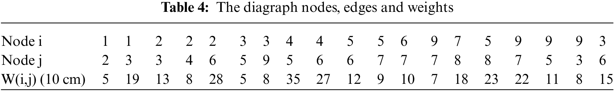
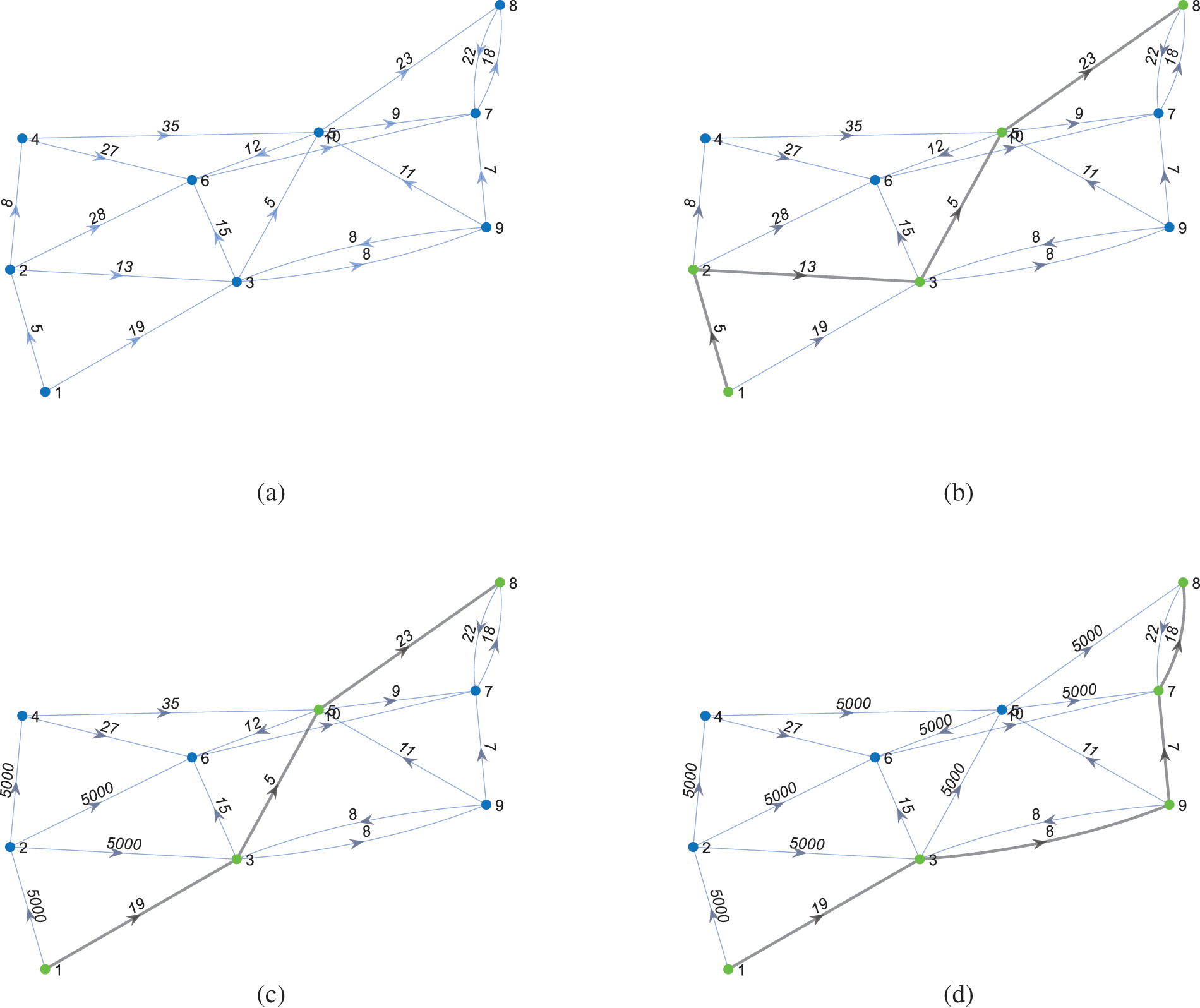
Figure 3: Illustration of the diagraphs of the path planning and obstacle avoidance implementation
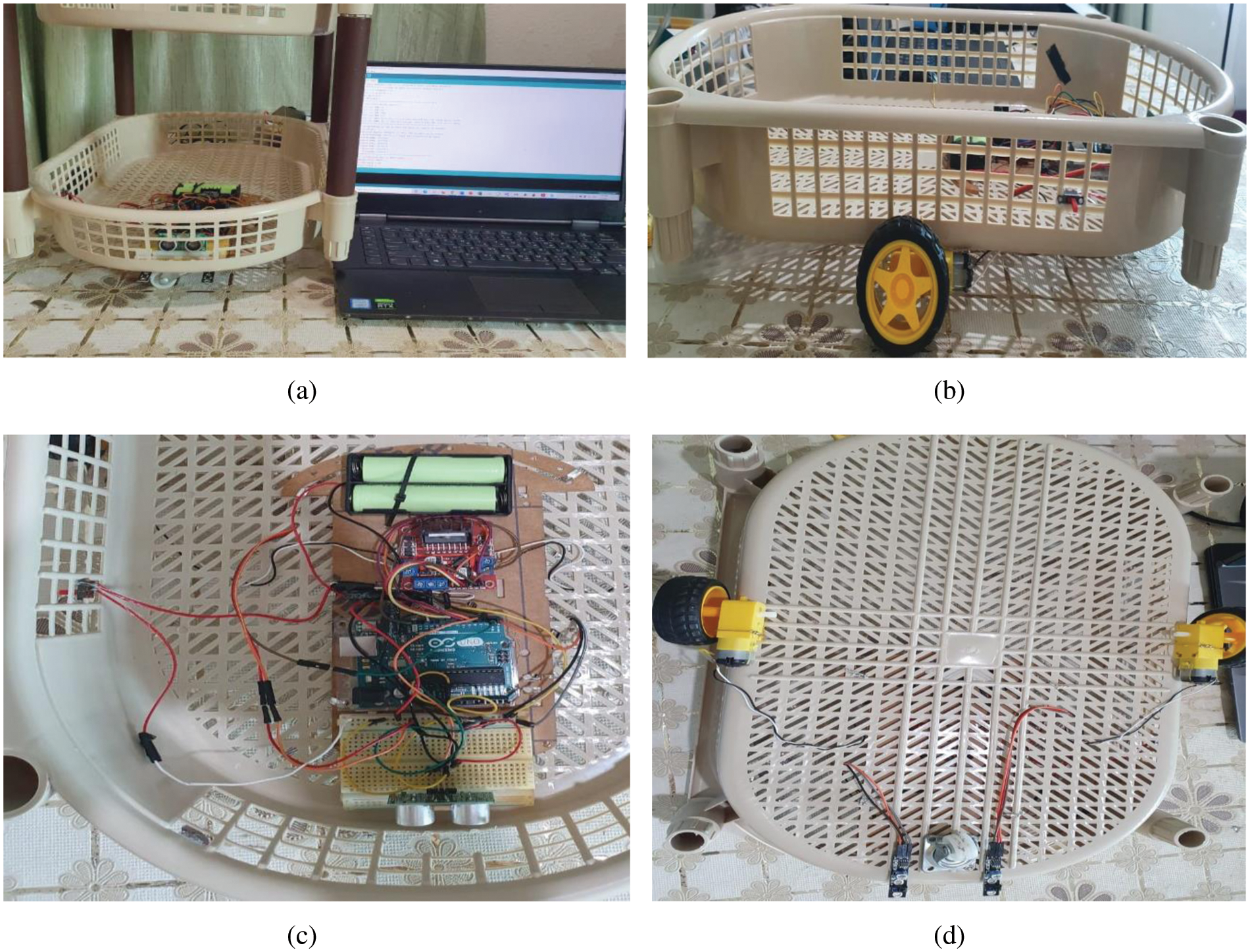
Figure 4: Experimental setup views: (a) Front (b) Left side (c) Top (d) Bottom
Dijkstra shortest path algorithm (Algorithm 1) was run on the diagraph of Fig. 3a. The starting vertex was chosen as #1 and the target vertex is #8. The obtained optimal path is found to be Q’ = {1, 2, 3, 5, 8} (Fig. 3b) and the optimal length is found to be 460 cm. Two obstacles were arbitrarily placed in nodes 2 and 5. As per the designed algorithm, the MR should stop at every node it reaches in order to test the existence of eventual obstacles at its adjacent node. From the beginning, since an obstacle exists in node 2, the MR should update its path by applying algorithm 1 to the diagraph after excluding node 2. Node 2 is here excluded by assigning a high value (5000 in our case) to all edges connecting it to all its adjacent nodes. The optimal path is then updated to become Q’ = {1, 3, 5, 8} (Fig. 3c) having 470 cm as length. The MR should move now to node 3. While stopping at node 3, the MR tests if there is any obstacle in the next optimal path node. Since node 5 includes an obstacle, the optimal path is updated by excluding node 5 using the same way as in node 2. Algorithm 1 is run on the new diagraph. The final optimal path is Q’ = {1, 3, 9, 7, 8} (Fig. 3d) having 520 cm as an optimal length. Since the improved Dijkstra algorithm developed in this paper is big-O(n2), its convergence time is proportional to the square of the number of nodes in the diagraph modeling the environment. In practice, the MR is expected to operate indoor where the number of nodes is relatively small and consequently the convergence time will be relatively small. The convergence time depends also on the microcontroller on which the algorithm is implemented. In our case, the used Arduino board has acceptable computational efficiency and memory capacity which achieved in this case study good performance.
4.4 Experimental Setup and Implementation
In order to practically implement the optimal path avoiding obstacles, an experimental setup around the DIY MR designed and assembled in the previous sections (Fig. 4) will be used.
In order to make the MR follow the optimal path marked using a black line, two KY-033 line-follower sensors have been used [27]. The line following logic is provided in Tab. 5. Theoretically, the MR can track the trajectory at any velocity less than its maximum velocity. However, during the experimentations, we were limited to the half of the maximum velocity for educational purpose in order to prevent losing trajectory tracking characteristic.
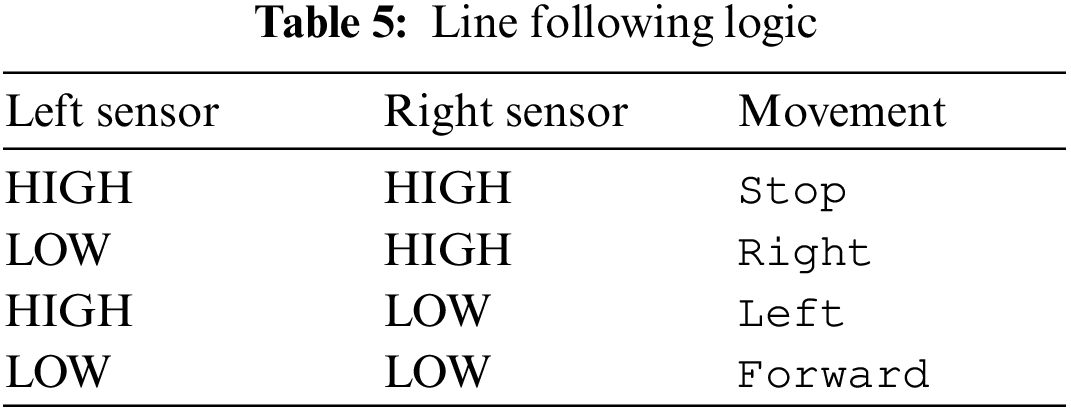
Based on Tab. 5, the optimal path is transferred into motion control movement as depicted in the movement sequence illustrated in Fig. 5.
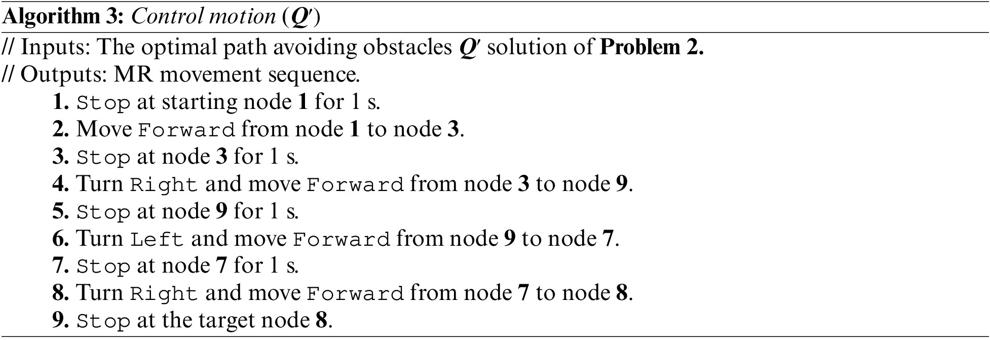
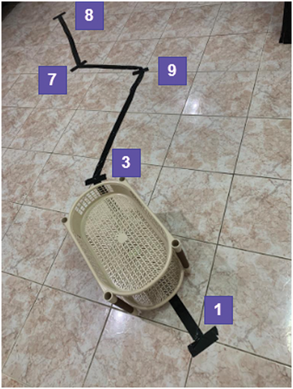
Figure 5: Illustration of the path planning avoiding obstacles
In this paper, a low-cost robotics platform for education and research purposes has been designed and implemented in the first part. The educational aim of this platform is to implement Science-Technology-Engineering-Art-Mathematics (STEAM) framework using an affordable system. The progressive steps of implementation included the mechanical 3D design, the hardware specification and the programming. In the second part of the paper, an optimal path planning avoiding obstacles algorithm has been developed based on an improved Dijkstra algorithm usually operating in environments without obstacles. The main contributions of this paper are the systematic procedure used in sizing and implementation of the mobile robot and the modification reported to the diagraph using a technique excluding the nodes including obstacles. The designed robot can support two to three trays which makes it useful for indoor logistics operations as well as in nonholonomic MR identification and control. In addition, the MR is extendable to other applications in computer vision and artificial intelligence. Implementing other path planning algorithms and comparing them to the improved Dijkstra algorithm are expected as perspectives of the current study.
Funding Statement: This research has been funded by Scientific Research Deanship at University of Ha’il – Saudi Arabia through Project Number BA-2107.
Conflicts of Interest: The authors declare that they have no conflicts of interest to report regarding the present study.
2https://www.robotshop.com/community/blog/show/drive-motor-sizing-tool
1. F. Arvin, J. Espinosa, B. Bird, A. West, S. Watson et al., “Mona: An affordable open-source mobile robot for education and research,” Journal of Intelligent & Robotic Systems, vol. 94, pp. 761–775, 2019. [Google Scholar]
2. A. Araujo, D. Portugal, M. S. Couceiro and R. P. Rocha, “Integrating arduino-based educational mobile robots in ROS,” Journal of Intelligent & Robotic Systems, vol. 77, pp. 281–298, 2015. [Google Scholar]
3. N. K. Cakir and G. Guven, “Arduino-assisted robotic and coding applications in science teaching: Pulsimeter activity in compliance with the 5E learning model,” Science Activities, vol. 56, no. 2, pp. 42–51, 2019. [Google Scholar]
4. L. A. P. Fuentes-dur, “Low-cost printable robots in education,” Journal of Intelligent & Robotic Systems, vol. 81, pp. 5–24, 2016. [Google Scholar]
5. H. Hu, “An educational arduino robot for visual deep learning experiments,” International Journal of Intelligent Robotics and Applications, vol. 4, pp. 73–81, 2020. [Google Scholar]
6. R. Limosani, A. Manzi, A. Faggiani, M. Bianchi, M. Pagliai et al., “Low-cost solution in international robotic challenge: Lessons learned by tuscany robotics team at ERL emergency robots 2017,” Journal of Field Robotics, vol. 36, no. 3, pp. 587–601, 2019. [Google Scholar]
7. M. L. Francisco and F. Cuesta, “Andruino-a1: Low-cost educational mobile robot based on android and arduino,” Journal of Intelligent & Robotic Systems, vol. 81, pp. 63–76, 2016. [Google Scholar]
8. J. M. Garc, C. Balaguer and M. A. Salichs, “Developing educational printable robots to motivate university students using open source technologies,” Journal of Intelligent & Robotic Systems, vol. 81, pp. 25–39, 2016. [Google Scholar]
9. E. Sancristobal, G. Carro, M. Castro and M. Blazquez, “European robotics week to introduce robotics and promote engineering,” Computer Applications in Engineering Education, vol. 26, no. 5, pp. 1068–1080, 2018. [Google Scholar]
10. P. Ponce, A. Molina, E. O. L. Caudana, G. B. Reyes and N. M. Parra, “Improving education in developing countries using robotic platforms,” International Journal in Interactive Design and Manufacturing, vol. 13, no. 4, pp. 1401–1422, 2019. [Google Scholar]
11. E. S. Pérez, “An ultra-low cost line follower robot as educational tool for teaching programming and circuit’s foundations,” Computer Applications in Engineering Education, vol. 27, pp. 288–302, 2019. [Google Scholar]
12. A. Eguchi, “Robocupjunior for promoting STEM education, 21st century skills, and technological advancement through robotics competition,” Robotics and Autonomous Systems, vol. 75, pp. 692–699, 2016. [Google Scholar]
13. J. Manuel, S. López, M. Luisa, S. García and E. Vazquez, “The effect of programming on primary school students’ mathematical and scientific understanding: Educational use of mBot,” Educational Technology Research and Development, vol. 67, no. 6, pp. 1405–1425, 2019. [Google Scholar]
14. D. Scaradozzi, L. S. L. Cesaretti and M. S. E. Mazzieri, “Implementation and assessment methodologies of teachers’ training courses for sTEM activities,” Technology, Knowledge and Learning, vol. 24, no. 2, pp. 247–268, 2019. [Google Scholar]
15. M. Lei, I. M. Clemente and Y. Hu, “Computers & education student in the shell: The robotic body and student engagement,” Computers & Education, vol. 130, pp. 59–80, 2019. [Google Scholar]
16. C. Vandevelde, F. Wyffels, B. Vanderborght and J. Saldien, “Design and evaluation of a DIY construction system for educational robot kits,” International Journal of Technology Design and Education, vol. 26, no. 4, pp. 521–540, 2016. [Google Scholar]
17. B. Zhong and L. Xia, “A systematic review on exploring the potential of educational robotics in mathematics education,” International Journal of Science and Mathematics Education, vol. 18, pp. 79–101, 2020. [Google Scholar]
18. A. Soriano, L. Mar, C. De Vera and E. Valencia, “Low cost platform for automatic control education based on open hardware,” in Proc. of the 19th World Congress the Int. Federation of Automatic Control Cape Town, South Africa, pp. 9044–9050, 2014. [Google Scholar]
19. N. M. F. Ferreira, A. Araujo and M. S. Couceiro, “Applied computing and informatics intensive summer course in robotics – robotcraft,” Applied Computing and Informatics, vol. 16, no. 1/2, pp. 155–179, 2018. [Google Scholar]
20. S. Oltean, “Mobile robot platform with arduino Uno and raspberry Pi for autonomous navigation,” Procedia Manufacturing, vol. 32, pp. 572–577, 2019. [Google Scholar]
21. M. Larra, “Experiences incorporating lego mindstorms robots in the basic programming syllabus: Lessons learned,” Journal of Intelligent & Robotic Systems, vol. 81, pp. 117–129, 2016. [Google Scholar]
22. A. F. Ribeiro and G. Lopes, “Learning robotics: A review,” Current Robotics Reports, vol. 1, pp. 1–11, 2020. [Google Scholar]
23. M. Jdeed, M. Schranz and W. Elmenreich, “A study using the low-cost swarm robotics platform spiderino in education,” Computers and Education Open, vol. 1, no. April, 2020. [Google Scholar]
24. W. G. Ali, “A semi-autonomous mobile robot for education and research,” Journal of King Saud University-Engineering Sciences, vol. 23, no. 2, pp. 131–138, 2011. [Google Scholar]
25. I. Jawaid, “Robotic system education for young children by collaborative-project-based learning,” Computer Applications in Engineering Education, vol. 28, pp. 178–192, 2020. [Google Scholar]
26. L. Malinverni, C. Valero, M. Monique, I. Garcia and D. Cruz, “Educational robotics as a boundary object: Towards a research agenda,” International Journal of Child-Computer Interaction, vol. 29, pp. 100305, 2021. [Google Scholar]
27. R. Farkh, K. S. Alhuwaimel and M. T. Quasim, “A deep learning approach for the mobile-robot motion control system,” Intelligent Automation & Soft Computing, vol. 29, no. 2, pp. 423–435, 2021. [Google Scholar]
28. Z. Durakli and V. Nabiyev, “A new approach based on bezier curves to solve path planning problems for mobile robots,” Journal of Computational Science, vol. 58, pp. 101540, 2022. [Google Scholar]
29. K. Karur, N. Sharma, C. Dharmatti and J. E. Siegel, “A survey of path planning algorithms for autonomous vehicles,” Vehicles, vol. 3, pp. 448–468, 2021. [Google Scholar]
30. Y. Chen, J. Liang, Y. Wang, Q. Pan, J. Tan et al., “Autonomous mobile robot path planning in unknown dynamic environments using neural dynamics,” Soft Computing, vol. 24, no. 18, pp. 13979–13995, 2020. [Google Scholar]
31. R. J. Wai, C. M. Liu and Y. W. Lin, “Design of switching path-planning control for obstacle avoidance of mobile robot,” Journal of the Franklin Institute, vol. 348, no. 4, pp. 718–737, 2011. [Google Scholar]
32. L. S. Liu, J. F. Lin, J. X. Yao, D. W. He, J. S. Zheng et al., “Path planning for smart Car based on dijkstra algorithm and dynamic window approach,” Wireless Communications and Mobile Computing, vol. 2021, pp. 1–6, 2021. [Google Scholar]
33. I. Sung, B. Choi and P. Nielsen, “On the training of a neural network for online path planning with offline path planning algorithms,” International Journal of Information Management, vol. 57, pp. 102142, 2021. [Google Scholar]
34. A. Maoudj and A. Hentout, “Optimal path planning approach based on Q-learning algorithm for mobile robots,” Applied Soft Computing Journal, vol. 97, pp. 106796, 2020. [Google Scholar]
35. H. M. Zhang and M. L. Li, “Rapid path planning algorithm for mobile robot in dynamic environment,” Advances in Mechanical Engineering, vol. 9, no. 12, pp. 1–12, 2017. [Google Scholar]
36. J. Wang, Y. Luo and X. Tan, “Path planning for automatic guided vehicles (AGVs) fusing MH-RRT with improved TEB,” Actuators, vol. 10, no. 12, pp. 314, 2021. [Google Scholar]
 | This work is licensed under a Creative Commons Attribution 4.0 International License, which permits unrestricted use, distribution, and reproduction in any medium, provided the original work is properly cited. |