DOI:10.32604/cmc.2022.028434
| Computers, Materials & Continua DOI:10.32604/cmc.2022.028434 | |
| Article |
Subcarrier BD with Cooperative Communication for MIMO-NOMA System
Department of Information and Communication Engineering, and Convergence for Intelligent Drone, Sejong University, Seoul, 05006, Korea
*Corresponding Author: Hyoung-Kyu Song. Email: songhk@sejong.ac.kr
Received: 09 February 2022; Accepted: 13 March 2022
Abstract: With the rapid evolution of Internet of things (IoT), many edge devices require simultaneous connection in 5G communication era. To afford massive data of IoT devices, multiple input multiple output non-orthogonal multiple access (MIMO-NOMA) method has been considered as a promising technology. However, there are numerous drawbacks due to error propagation and inter-user interferences. Therefore, proposed scheme aims to improve the reliability of the MIMO-NOMA system with digital beamforming and intra-cluster cooperative multi point (CoMP) to efficiently support IoT system. In the conventional MIMO-NOMA system, user entities are grouped into clusters. Block diagonalization (BD) is applied to efficiently eliminate the inter-cluster interference of the MIMO-NOMA system. However, since the channel path of the data stream from a single antenna to a single cluster doesn’t hold other cluster’s data, the system can’t fully utilize the selective subcarrier channel states. It indicates that there can be better channel paths for a data stream at a certain subcarrier index. Therefore, proposed scheme allocates data streams to antennas adaptively considering selective channel states. Additionally, intra-cluster CoMP method is adjusted to enhance the reliability of the system in the clusters. The simulation results show that the proposed scheme improves BER and throughput performance compared to the conventional MIMO-NOMA system.
Keywords: 5G; MIMO-NOMA; CoMP; BD; interference
Evolution of the IoT led the channel capacity requirement reaches the limit of the conventional specification [1]. Mobile phones, drones, signages, wearable devices, electric home appliances and much more electronic devices require massive connectivity and thus require huge amount of channel capacity. There have been user multiplexing technologies for the transmitter to accommodate multiple devices throughout the history [2,3]. Frequency division multiple access (FDMA), time division multiple access (TDMA), code division multiple access (CDMA), and orthogonal frequency division multiple access (OFDMA) were the key multiplexing technologies from 1G to 4G communication era [3–6]. FDMA, TDMA, CDMA, and OFDMA are known as orthogonal multiple access (OMA) schemes. However, since low-cost and low-power are essential requirements to maintain IoT, new multiplexing technology has emerged to meet the requirements. The orthogonal property of OMA reached its limit of channel capacity, thus it requires more elements and components to accommodate IoT devices. Therefore, NOMA has emerged to meet the requirements for data rate and capacity [7–10]. NOMA accommodates multi-user data with non-orthogonal resource. However, NOMA has drawbacks due to its own non-orthogonal property which divides multi-user data with power. Successive interference cancellation (SIC) process is necessary for the receivers to extract the data from the received data [11,12]. This process propagates error. It gets worse as the number of user entities increases in the system.
To overcome the problem of the NOMA, numerous researches have suggested various methods. Single input multiple output-NOMA (SIMO-NOMA) aimed to efficiently eliminate inter user interference and error propagation by applying instantaneous user grouping and receive diversity with the structure of the instantaneous user grouping [13]. However, it has total transmit power limit since the system only has one transmit antenna. Certain user data can’t be allocated to any other subcarriers in the SIMO-NOMA system. This leads to throughput loss of each user data. In order to break the limit of transmit power and throughput, multiple input multiple output-NOMA (MIMO-NOMA) system is considered in the field. With the structure of the MIMO-NOMA system, beamforming can be used to efficiently eliminate inter-user interference and enhance overall bit error rate (BER) performance. There are numerous works to enhance the performance of MIMO-NOMA system with beamforming. Choi [14] suggested user ordering and generalization to improve the BER performance and formulated semidefinite programming (SDP) problem to find optimal beamforming vectors. Since there can be a lot of user grouping sets in the system, generalized NOMA beamforming to determine appropriate SIC sets can be promising. Zhu et al. [15] suggested beamforming design to maximize the weighted sum rate, considering decoding order constraints and quality of service (QoS) constraints. The design is formulated as a weighted sum rate maximization (WSRM) problem, and it admits the favorable convexity in the situation of homogeneous channel. Liu et al. [16] suggested an optimal power allocation scheme with imperfect channel state information (CSI). It shows that the suggested scheme can increase the users’ capacity and maintain the user fairness by employing regularized zero-forcing (ZF) precoding which has good performance-complexity balance. However, in [14], calculation process to determine the best SIC set is complex. In [15], convexity of the NOMA WSRM beamforming problem can only be found in the situation of homogeneous channels. In [16], proposed ZF precoding is not the best option to eliminate inter-user interference. Moreover, these previous works did not consider the allocation of a cluster data to every transmit antenna according to selective subcarrier channel states. Since the previous works did not consider selective subcarrier channel states, it’s hard to fully utilize every channel paths for their data.
Therefore, the proposed scheme in this paper applies subcarrier digital beamforming scheme to fully utilize every channel paths for every user data. Full digital beamforming is adjusted in this paper with sub-connected structure. Transmit power, which is important in evolution of IoT, can be saved with the beamforming. There are many digital precoding schemes to eliminate inter-user interference. The proposed scheme uses BD precoding scheme which makes inter-user interference into 0. With the feedback information, transmitter analyzes each subcarrier channel states and allocates all user data to every antennas. Accordingly, BD precoding is applied throughout every single subcarriers to fully utilize all channel paths. Cooperative communication method is also adjusted to further enhance the BER performance of the MIMO-NOMA system. Decode and forward (DF) method is used as a simple solution to eventually combine the received data with diversity scheme. These schemes enable low-cost and low-power principle to maintain IoT efficiently. Also, proposed schemes can efficiently transmit data that is required precise as [17,18].
This paper is organized as follows. Section 2 describes system model. Section 3 describes the proposed method. Section 4 shows the simulation results. Finally, Section 5 concludes this paper.
This section describes NOMA with MIMO beamforming. Since beamforming can be applied to the system when the transmitter has multiple antennas, conventional scheme aims to apply beamforming on MIMO-NOMA system. Fig. 1 shows the overview of the LTE sidelink transmission. Unlike LTE-Uu communication interface between user entity and base station, LTE-PC5 sidelink is used as device to device (D2D) direct communication link. Proposed scheme in this paper is based on this LTE sidelink. Because sidelink is direct communication between users without the base station, this technique can be used for expanding network coverage as Fig. 1. Now sidelink communication is also studied at vehicle communication (i.e., LTE/5G-V2X) [19].
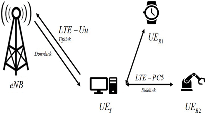
Figure 1: LTE sidelink overview
In LTE sidelink system, data are allocated in resource elements and transmitted by resource blocks which contain resource elements [20,21].
eNB is an enhanced telecommunications node in mobile communications networks. It provides connections between user entities (UEs) which are IoT devices. UET and UER stands for transmitter UE and receiver UE respectively. UET which performs digital beamforming has multiple antennas. It applies sub-connected beamforming architecture to lower the hardware complexity [22]. Channel model of the LTE sidelink is assumed as 7 path Rayleigh fading channel.
This subsection describes the conventional user grouping NOMA system which was represented in [13]. Fig. 2 shows the difference between power domain NOMA without user grouping method and with user grouping method in the case of 4 IoT devices.
P, f, and BT represent power, frequency and total bandwidth of the signal respectively. All user data are allocated in a single subcarrier and transmitted at the same time in the NOMA system without user grouping. Since the total transmit power is limited, it should be divided into the number of user entities. Therefore, error propagation and inter-user interference get larger as the number of user entities increases. However, user grouping method is applied to minimize the error propagation and inter-user interference by grouping multi user data into two in a single subcarrier.
This subsection points out that the user grouping method in [13] has remaining problem. According to the right picture of the Fig. 2, data of user A and B apparently occupies only half of the total bandwidth BT. It appears that bandwidth occupation of a single user decreases as the number of user entities increases in the conventional user grouping NOMA system. This also decreases the throughput of the user data. Therefore, the system of the proposed scheme aims to increase transmit antenna in order to raise total transmit power.
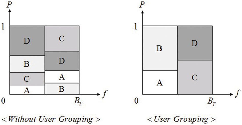
Figure 2: User grouping method in the case of 4 IoT devices
2.2 MIMO-NOMA Digital Beamforming Scheme
This subsection describes NOMA system based on MIMO. Fig. 3 shows the system model of the MIMO-NOMA in the case of 4 IoT devices. UET transmits superimposed data to 4 user entities simultaneously in the system model. According to [13], every user data is allocated to different subcarriers with the channel coefficients. Since the MIMO system in this paper has 4 transmit antennas, the data transmission can be described as Fig. 4.
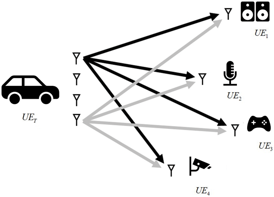
Figure 3: MIMO-NOMA in the case of 4 IoT devices
Txi, Rxj, hji, and sk represent the i-th transmit antenna, the j-th receive antenna, the channel from the i-th transmit antenna to the j-th receive antenna and the k-th subcarrier respectively. In the superimposed data which are transmitted by Tx1 and Tx2, there are the data of UE1 and UE2. In the superimposed data which are transmitted by Tx3 and Tx4, there are the data of UE3 and UE4. When all the superimposed data pass through channel h11 through h14, Rx1 finally receives the data. Received data y1 can be represented as follows,
where
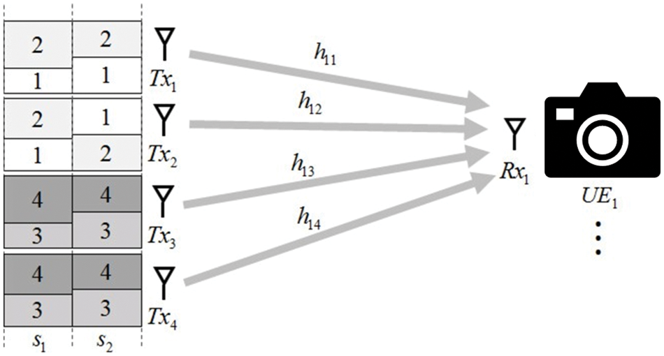
Figure 4: MIMO-NOMA data transmission
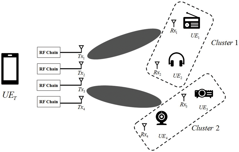
Figure 5: MIMO-NOMA with digital beamforming
An RF chain is a cascade of electronic components which may include filters, amplifiers, attenuators, and mixers. It is attached behind a single antenna in the digital beamforming system. Each antenna can construct a beam toward users. Since IoT devices are partitioned into two clusters, 4 transmit antennas construct 2 beams. Tx1 and Tx2 emit beam toward cluster 1. Tx3 and Tx4 emit beam toward cluster 2. Beam from Tx1 and Tx2 only contains superimposed data of UE1 and UE2. Beam from Tx3 and Tx4 only contains superimposed data of UE3 and UE4. However, there are channel paths between Tx1, Tx2 and cluster 2. There are also channel paths between Tx3, Tx4 and cluster 1. Received data from these channel paths are regarded as interferences. Interference from Tx3 and Tx4 must be eliminated for cluster 1 to efficiently demodulate the data of UE1 and UE2. Interference from Tx1 and Tx2 must be eliminated for cluster 2 to efficiently demodulate the data of UE3 and UE4 as well. The interference elimination process can be done by BD.
3.1 Subcarrier Block Diagonalization with Antenna Selection
Conventional method divides total users into clusters and transmits user data with multi antennas. Each antenna contains each data of the clusters in the conventional MIMO-NOMA digital beamforming system. However, the conventional method can’t adjust every subcarrier channel state of the clusters since it allocates the data of cluster 1 to Tx1 and allocates the data of cluster 2 to Tx2. However, certain subcarrier channel state can be better than the channel state from Tx2 to cluster 1. It indicates that the conventional MIMO-NOMA digital beamforming method does not use an optimal channel for the system. Therefore, this paper proposes subcarrier BD with antenna selection to efficiently adjust every subcarrier channel states according to the utilization of every channel paths.
Transmitter should know the channel coefficients to adjust the proposed scheme to every data stream. It is assumed that the channel estimation and feedback are perfect for research simplification. The BD from the transmitter proceeds as follows,
where,
After defining the
where
Digital precoding matrix
It can be seen that
However, unlike conventional MIMO-NOMA scheme, proposed scheme considers channel coefficients throughout subcarriers. Fig. 6 shows the antenna selection performed in transmit antenna Tx1 and Tx4. Left side of the Fig. 6 is the conventional MIMO-NOMA while the right side of the Fig. 6 is the proposed MIMO-NOMA adjusting subcarrier BD with antenna selection.
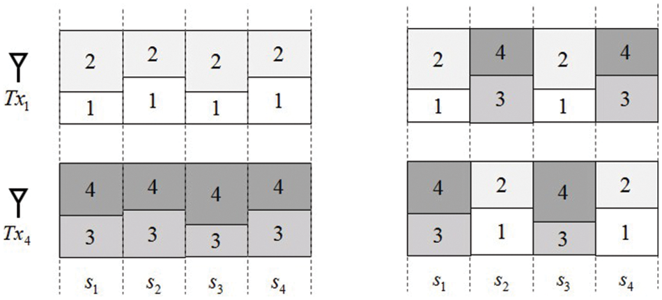
Figure 6: Subcarrier BD with antenna selection
In the perspective of the subcarrier data in s2, data of UE3 and UE4 are located in the stream from Tx4. It is always fixed throughout the whole subcarriers in the conventional MIMO-NOMA system. However, there can be variety of beam sets that can be made according to the channel states in the proposed MIMO-NOMA system. The average channel state of a certain beam set can be better than the others in a certain subcarrier. Therefore, it is better to switch data streams of cluster 1 and 2 among the transmit antennas. Antenna selection enables the system to utilize every channel paths which are the best beam sets for each subcarrier. Fig. 7 shows the antenna selection beam sets of 4 × 4 MIMO-NOMA system. There are 6 possible beam sets in the proposed system. Proposed scheme determines which beam set is the best choice for the system in each subcarrier. The determination is done by comparing channel power summation of the beam sets. By applying subcarrier BD with antenna selection, proposed scheme aims to utilize every channel states to select the best beam set of data streams in each subcarrier. Since the channel set changes according to channel power comparison in every subcarrier channel states, BD procedure should calculate SVD with different
1. for
2. for i = 1: number of transmit antenna
3. calculate channel power summation of each user in
end for
end for
1. Compare each power summation result
2. Select beam set {
where
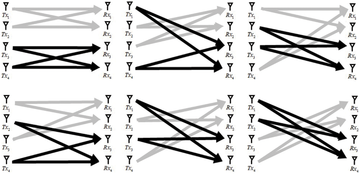
Figure 7: Antenna selection beam sets of 4 × 4 MIMO-NOMA system
3.2 Intra-Cluster Cooperative Scheme
This subsection introduces intra-cluster cooperative scheme to additionally enhance the reliability of the proposed MIMO-NOMA system. In the conventional MIMO-NOMA system using BD to eliminate inter-user interference, overall BER performance degrades as the number of user entity increases. BD can efficiently eliminate the interferences. However, it can’t eliminate noise. Therefore, if there are more user entities in the system, noise at each receiver becomes large. To enhance the reliability of the system, cooperative scheme adopted proposed system. It can be adjusted in the clusters which are consisted with 2 user entities. One user entity in a cluster extracts its data which large power is allocated, and the other user entity in the cluster extracts its data with SIC which small power is allocated. Small power is allocated since the channel state between transmitter and the receiver user entity is worse compared to the other. BER performance can’t be reliable since the data is allocated with small power as Fig. 8. Therefore, the user entity which has its data with large power proceeds SIC to extract the data with small power and forwards it to the user entity which has its own data with small power. Transmitter becomes source, the user entity which forwards the data becomes relay, and the user entity which receives the forwarded data becomes destination.
Following equations are the procedures where Tx1 transmits the superimposed data of UE1 and UE2 through h11 and h21. The received data y1 and y2 can be represented as follows,
UE1 extracts its own data by dividing y1 into the large power p1. Then, it proceeds SIC calculation to extract the data of UE2. The cooperative communication proceeds as follows,
where
where
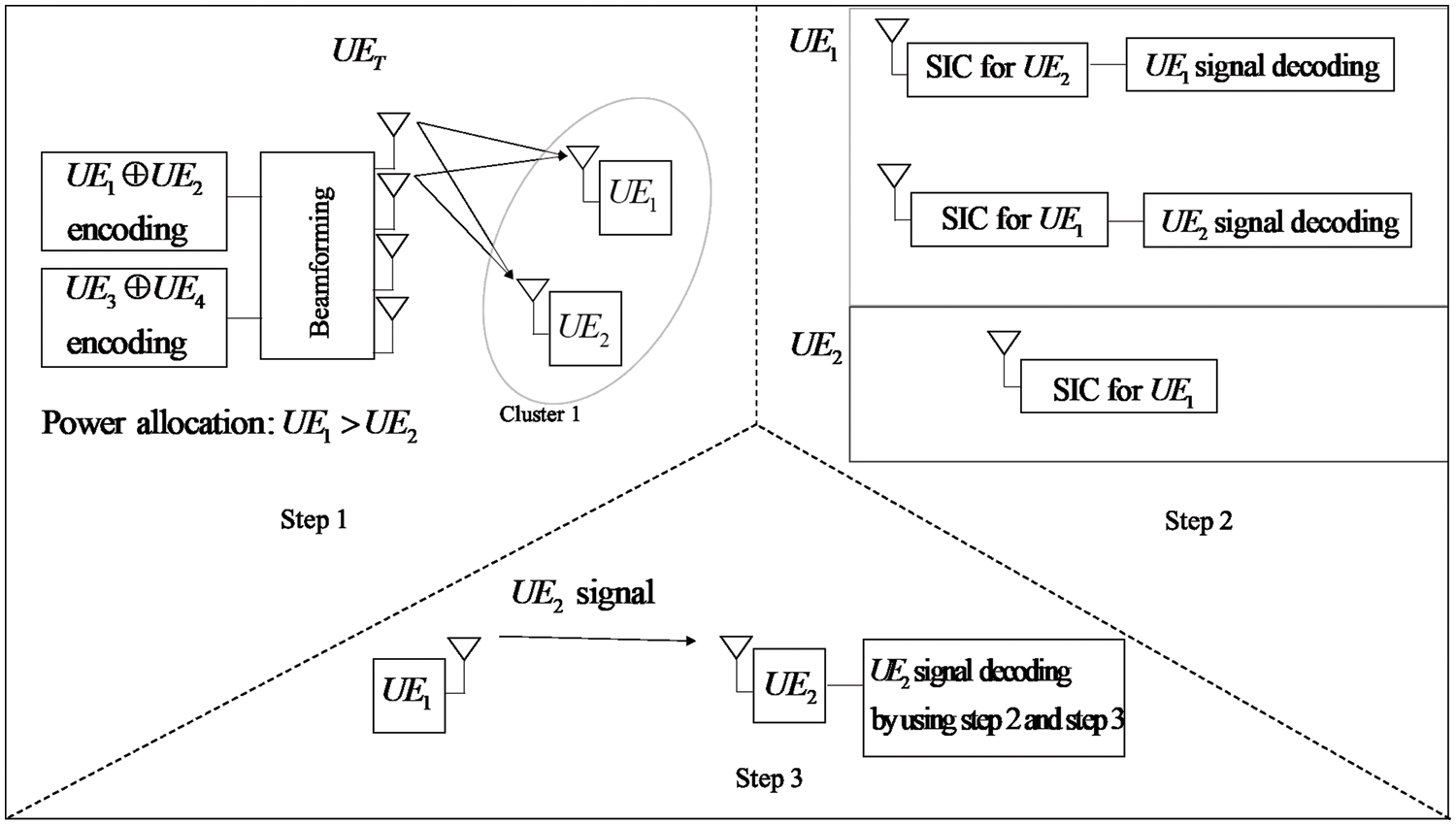
Figure 8: Summarized block diagram of inter-cluster cooperative communication
This section shows the simulation results of the proposed scheme. The Tab. 1 shows the simulation parameters of the proposed system. The simulation is based on LTE sidelink system. Therefore, the simulation parameters are based on third generation partnership project (3GPP) technical specifications. The system uses bandwidth of 10 MHz. Fast Fourier transform length is 1024. Long cyclic prefix and short cyclic prefix for the LTE sidelink transmission are 80 and 72 respectively. Simulations are performed under the circumstances which has 4 user entities and 6 user entities. Each user entity has single antenna in both circumstances while the transmitter is equipped with 4 and 6 transmit antennas. BPSK and QPSK modulation are adjusted to show the performance difference between modulation orders. 1/2 convolutional coding is used with the constraint length of 7. Rayleigh channel with 7 paths is used as a channel model of the proposed MIMO-NOMA system.
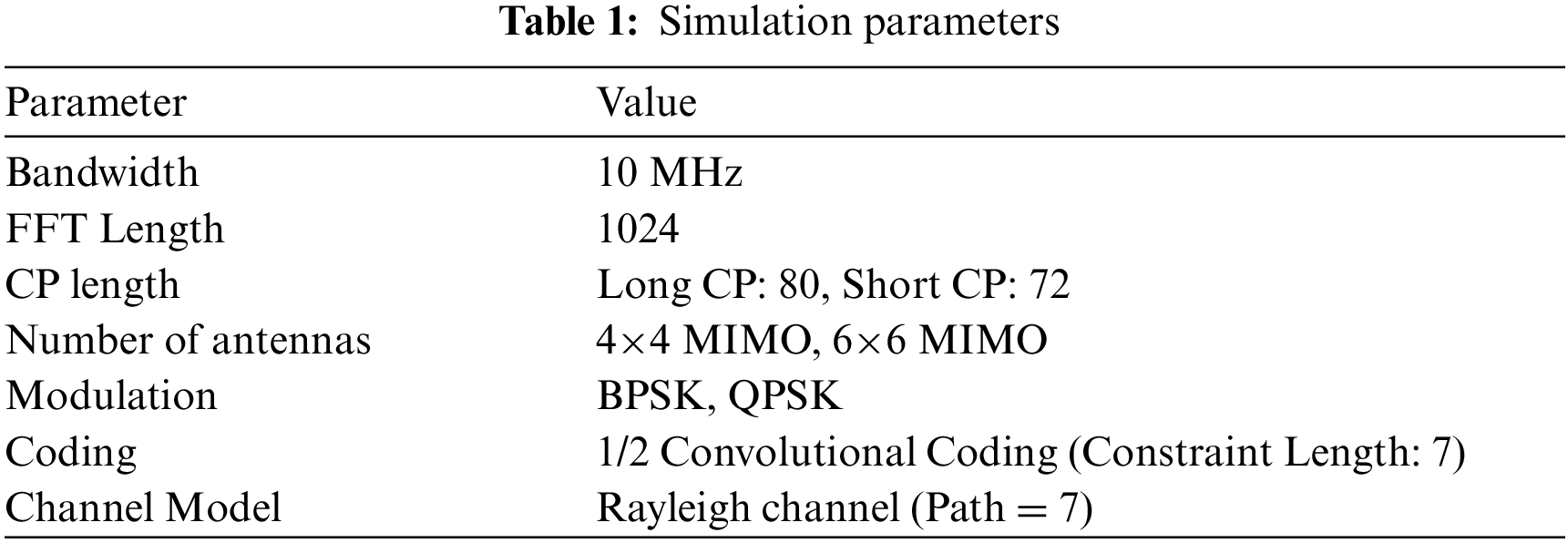
Fig. 9 shows the BER performance of proposed MIMO-NOMA scheme with the conventional MIMO-NOMA scheme in the case of 4 users. It can be seen that the performance of the proposed scheme has 1 dB SNR gain with BPSK modulation, and 2 dB SNR gain with QPSK modulation at BER of
Fig. 10 shows the throughput performance of the proposed MIMO-NOMA scheme with the conventional MIMO-NOMA scheme in the case of 4 users. The maximum throughput is not different between the proposed scheme and the conventional scheme since both schemes use every multi antennas in the transmitter. However, the proposed scheme reaches the maximum throughput at lower SNR than the conventional scheme. The maximum throughput of the QPSK is 2 times larger than the maximum throughput of the BPSK. It can also be seen that the gap of the throughput performance between the conventional scheme and the proposed scheme, is larger on the case of QPSK than the case of BPSK. It is because QPSK holds twice more user data bits in a single data symbol. Therefore, the gap between the conventional scheme and the proposed scheme on the case of QPSK is approximately twice bigger than that of BPSK.
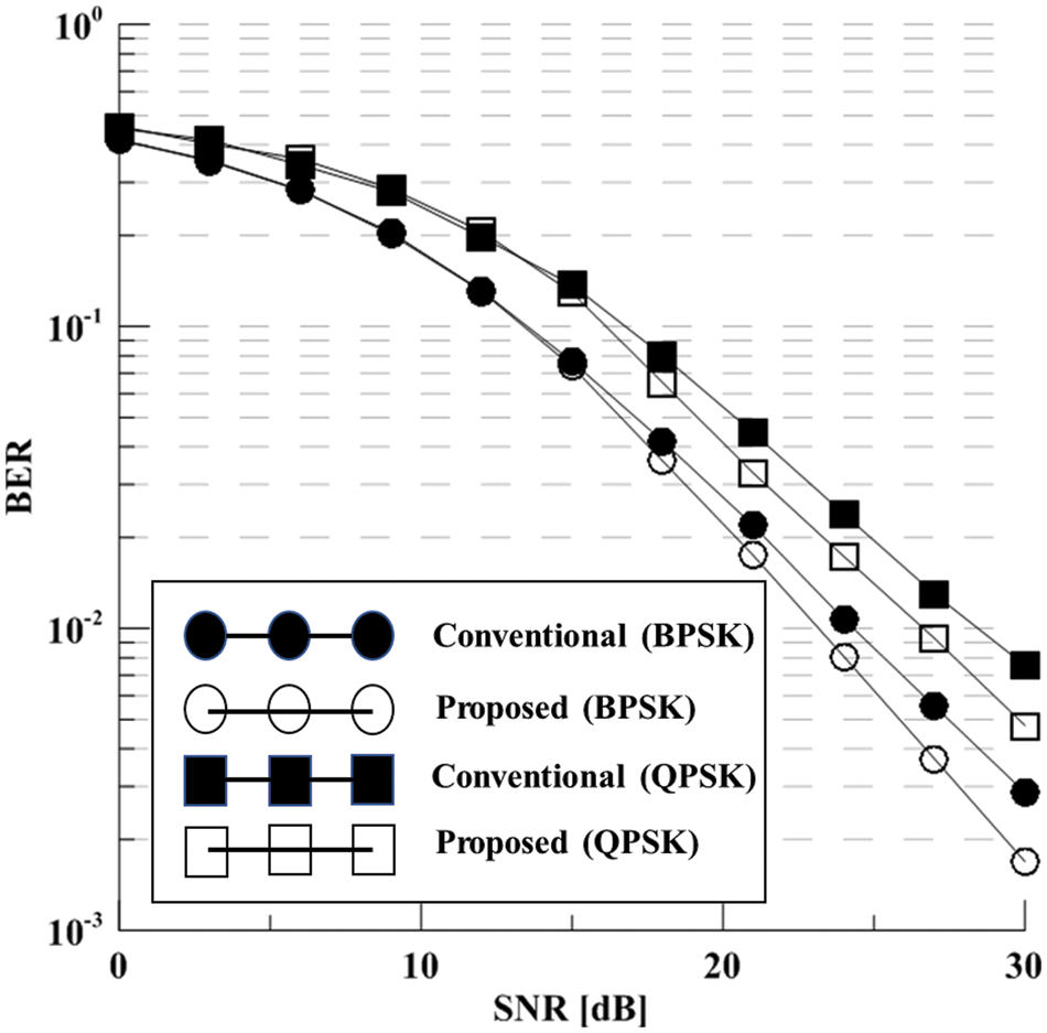
Figure 9: The BER performance of MIMO-NOMA scheme (4 × 4)
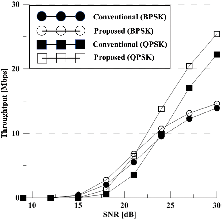
Figure 10: The throughput performance of MIMO-NOMA scheme (4 × 4)
Fig. 11 shows the BER performance of the proposed MIMO-NOMA scheme with the conventional MIMO-NOMA scheme in the case of 6 users. It can be seen that the performance of the proposed scheme has 1 dB SNR gain with BPSK modulation, and 1 dB SNR gain with QPSK modulation at BER of
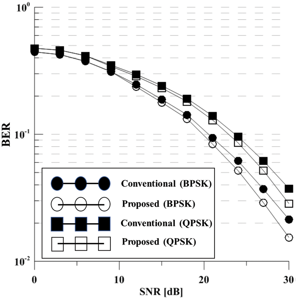
Figure 11: The BER performance of MIMO-NOMA scheme (6 × 6)
There are no performance differences at the low SNR region between the conventional scheme and the proposed scheme. However, the gap between the conventional scheme and the proposed scheme becomes non-zero at the higher SNR zone compared to the Fig. 9. It indicates that antenna selection method gets spatial diversity gain, since there are more antenna sets to choose from in 6 × 6 environment than in 4 × 4 environment.
Fig. 12 shows the throughput performance of the proposed MIMO-NOMA scheme and the conventional MIMO-NOMA scheme in the case of 6 users. Since the reliability of the system is lower than that of the system with 4 users, the throughput performance starts to rise at the higher point of SNR. It starts to rise at 18 dB. The proposed scheme apparently outperforms the conventional scheme. Since the graphs don’t reach its throughput limit, they continue to rise as the SNR goes up. It indicates that Fig. 12 only shows the initial state of the throughput performance at low SNR region.
Fig. 13 shows the throughput performance of the proposed MIMO-NOMA schemes in the case of 4 and 6 users and the SIMO-NOMA scheme with BPSK modulation. The proposed MIMO-NOMA scheme has significantly high throughput performance than the SIMO-NOMA system. Since the user data are allocated to different subcarriers in a single data stream, sum throughput is fixed whether the number of user entities increases or not. Therefore, proposed schemes which use multi transmit antennas and accommodate multi data stream can achieve the maximum throughput of the system. However, the throughput performance of the proposed scheme in the case of 6 users is lower than that of the SIMO-NOMA scheme at 20 dB. It indicates that the noise increased by the number of users affects the overall performance. Performance degradation due to the increase of user entities is critical. However, the proposed scheme increases the performance with BD and cooperative scheme.
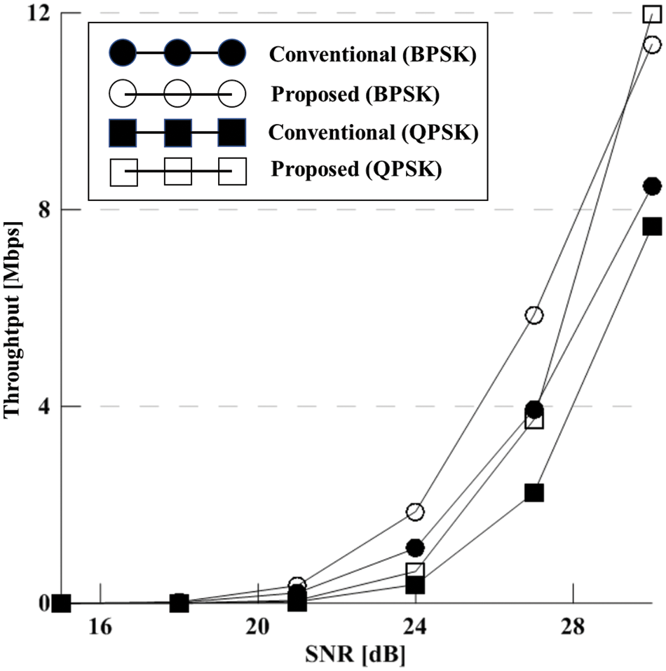
Figure 12: The throughput performance of MIMO-NOMA scheme (6 × 6)
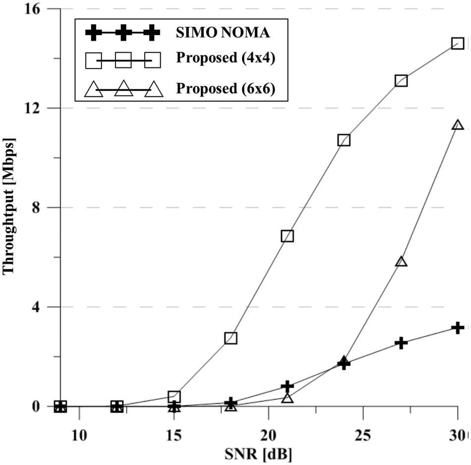
Figure 13: The throughput performance comparison (BPSK)
With the increasing amount of edge devices, wireless communication system which can hold massive user entities is required for the evolving IoT. Recently, with the further research and progress in the 5G communication, numerous states of the art methods have emerged in the field which are mmWave for bandwidth expansion, small cells for coverage, and massive MIMO beamforming for reliability. Among the methods, multiple access scheme called MIMO-NOMA is considered in this paper to eventually reduce cost and power of the IoT system. With the structure of the multi transmit antenna, the conventional system implies digital beamforming to eliminate inter-cluster interference. However, since the data stream from a single transmit antenna only consists data of single cluster to avoid inter-cluster interference, the system can’t fully utilize the subcarrier channel state. Since the channel states are selective, the proposed scheme utilizes every channel paths to obtain optimal performance gain. To further enhance the BER performance of the system, intra-cluster cooperative communication is additionally proposed. The first user entity which receives the superimposed data demodulates its data and performs SIC to extract the data of another user entity in the same cluster. Extracted data is transferred to the second user entity and the second user entity performs MRC to enhance the reliability. Therefore, the proposed scheme efficiently enhanced BER and throughput performance compared to the conventional MIMO-NOMA system and thus developed IoT system. Also, machine learning model for selecting antenna will be considered for the future work in 5G or beyond wireless communication system [27].
Funding Statement: This research was supported by Basic Science Research Program through the National Research Foundation of Korea (NRF) funded by the Ministry of Education (2020R1A6A1A 03038540) and was supported by Institute for Information & communications Technology Promotion (IITP) grant funded by the Korea government (MSIT) (No.2017-0-00217, Development of Immersive Signage Based on Variable Transparency and Multiple Layers).
Conflicts of Interest: The authors declare that they have no conflicts of interest to report regarding the present study.
1. P. Corcoran, “The internet of things: Why now, and what’s next?” IEEE Consumer Electronics Magazine, vol. 5, no. 1, pp. 63–68, 2015. [Google Scholar]
2. E. Erkip and B. Aazhang, “A comparative study of multiple accessing schemes,” in Conf. Record of the Thirty-First Asilomar Conf. on Signals, Systems and Computers, CA, USA, pp. 614–619, 1997. [Google Scholar]
3. H. Yin and S. Alamouti, “OFDMA: A broadband wireless access technology,” in 2006 IEEE Sarnoff Symp., NJ, USA, pp. 1–4, 2006. [Google Scholar]
4. J. Zhang, L. L. Yang, L. Hanzo and H. Gharavi, “Advances in cooperative single-carrier FDMA communications: Beyond LTE-Advanced,” IEEE Communications Surveys and Tutorials, vol. 17, no. 2, pp. 730–756, 2015. [Google Scholar]
5. D. D. Falconer, F. Adachi and B. Gudmundson, “Time division multiple access methods for wireless personal communications,” IEEE Communications Magazine, vol. 33, no. 1, pp. 50–57, 1995. [Google Scholar]
6. R. Prasad and T. Ojanpera, “A survey on CDMA: Evolution towards wideband CDMA,” in 1998 IEEE 5th Int. Symp. on Spread Spectrum Techniques and Applications, Sun City, South Africa, 1998. [Google Scholar]
7. J. G. Andrews, S. Buzzi, W. Choi, S. B. Hanly, A. Lozano et al., “What will 5G be?” IEEE Journal on Selected Areas in Communications, vol. 32, no. 6, pp. 1065–1082, 2014. [Google Scholar]
8. A. Benjebbour, A. Li, K. Saito, Y. Saito, Y. Kishiyama et al., “NOMA: From concept to standardization,” in 2015 IEEE Conf. on Standards for Communications and Networking, Tokyo, Japan, pp. 18–23, 2015. [Google Scholar]
9. Y. Chen, A. Bayesteh, Y. Wu, B. Ren, S. Kang et al., “Toward the standardization of non-orthogonal multiple access for next generation wireless networks,” IEEE Communications Magazine, vol. 56, no. 3, pp. 19–27, 2018. [Google Scholar]
10. L. Dai, B. Wang, Y. Yuan, S. Han, I Chih-lin et al., “Non-orthogonal multiple access for 5G: Solutions, challenges, opportunities, and future research trends,” IEEE Communications Magazine, vol. 53, no. 11, pp. 74–81, 2015. [Google Scholar]
11. K. Higuchi and A. Benjebbour, “Non-orthogonal multiple access (NOMA) with successive interference cancellation for future radio access,” IEICE Transactions on Communications, vol. 98, no. 3, pp. 403–414, 2015. [Google Scholar]
12. X. Chen, A. Beiijebbour, A. Li, H. Jiang and H. Kayama, “Consideration on successive interference canceller receiver at cell-edge users for non-orthogonal multiple access with SU-MIMO,” in 2015 IEEE 26th Annual Int. Symp. on Personal, Indoor, and Mobile Radio Communication, Hong Kong, China, pp. 522–526, 2015. [Google Scholar]
13. J. H. Kim, W. S. Lee and H. K. Song, “Performance enhancement using receive diversity with power adaptation in the NOMA system,” IEEE Access, vol. 7, pp. 102867–102875, 2019. [Google Scholar]
14. J. Choi, “On generalized downlink beamforming with NOMA,” Journal of Communications and Networks, vol. 19, no. 4, pp. 319–328, 2017. [Google Scholar]
15. F. Zhu, Z. Lu, J. Zhu, J. Wang and Y. Huang, “Beamforming design for downlink non-orthogonal multiple access systems,” IEEE Access, vol. 6, pp. 10956–10965, 2018. [Google Scholar]
16. X. Liu, J. Zhang and S. Cai, “An optimal power allocation scheme in downlink multi-user NOMA Beamforming System with Imperfect CSI,” in 2018 IEEE Int. Conf. on Communication Systems, Chengdu, China, pp. 99–103, 2018. [Google Scholar]
17. R. Zhang, W. F. Zhang, W. Sun, X. M. Sun and S. K. Jha, “A robust 3-D medical watermarking based on wavelet transform for data protection,” Computer Systems Science & Engineering, vol. 41, no. 3, pp. 1043–1056, 2022. [Google Scholar]
18. X. R. Zhang, X. Sun, X. M. Sun, W. Sun and S. K. Jha, “Robust reversible audio watermarking scheme for telemedicine and privacy protection,” Computers, Materials & Continua, vol. 71, no. 2, pp. 3035–3050, 2022. [Google Scholar]
19. M. Harounabadi, D. M. Soleymani, S. Bhuadauria, M. leyh and E. Roth-Mandutz, “V2X in 3GPP standardization: NR sidelink in release-16 and beyond,” IEEE Communications Standards Magazine, vol. 5, no. 1, pp. 12–21, 2021. [Google Scholar]
20. H. A. Ali, A. E. M. Taha, M. Salah and H. Hassanein, “Uplink scheduling in LTE and LTE-Adavanced: tutorial, survey and evaluation framework,” IEEE Communications Surveys and Tutorials, vol. 16, no. 3, pp. 1239–1265, 2013. [Google Scholar]
21. J. Hu, C. Li, J. Fang, L. Zhao and Y. Shi, “Enhanced resource selection mechanism for LTE-V2X sidelink multi-carrier operation,” in 2019 IEEE 89th Vehicular Technology Conf. (VCT2019-Spring), HI, USA, pp. 1–4, 2019. [Google Scholar]
22. P. L. Cao, T. J. Oechtering and M. Skoglond, “Transmit beamforming for single-user large-scale MISO systems with sub-connected architecture and power constraints,” IEEE Communications Letters, vol. 22, no. 10, pp. 2096–2099, 2018. [Google Scholar]
23. J. H. Ro, W. S. Lee, J. G. Ha and H. K. Song, “An efficient precoding method for improved downlink massive MIMO system,” IEEE Access, vol. 7, pp. 112318–112326, 2019. [Google Scholar]
24. W. S. Lee, M. J. Kim and H. K. Song, “Inter-relay interference cancellation using MIMO detection,” Wireless Personal Communications, vol. 98, no. 2, pp. 1885–1894, 2019. [Google Scholar]
25. W. C. Kim, M. J. Paek and H. K. Song, “Relay selection scheme for multi-hop transmission of MU-MIMO system,” Applied Sciences, vol. 8, no. 10, pp. 1–15, 2018. [Google Scholar]
26. K. S. G. Kiran and R. Swamiathan, “Performance analysis of DF-relaying-based cooperative NOMA System with partial relay selection,” in 2022 14th Int. Conf. on Communication Systems & NetworkS (COMSNETS), Bangalore, India, pp. 574–580, 2022. [Google Scholar]
27. Z. Kuai and S. Wang, “Thompson sampling-based antenna selection with partial CSI for TDD massive MIMO Systems,” IEEE Transactions on Communications, vol. 68, no. 12, pp. 7533–7546, 2020. [Google Scholar]
 | This work is licensed under a Creative Commons Attribution 4.0 International License, which permits unrestricted use, distribution, and reproduction in any medium, provided the original work is properly cited. |