DOI:10.32604/cmc.2022.021573
| Computers, Materials & Continua DOI:10.32604/cmc.2022.021573 | |
| Article |
FPGA Implementation of 5G NR Primary and Secondary Synchronization
1Department of ECE, VNR Vignana Jyothi Institute of Engineering & Technology, Hyderabad, 500090, India
2JNTUA, Former Vice Chancellor, India
*Corresponding Author: Aytha Ramesh Kumar. Email: Rameshkumar_a@vnrvjiet.in
Received: 07 July 2021; Accepted: 22 March 2022
Abstract: The 5G communication systems are widely established for high-speed data processing to meet users demands. The 5G New Radio (NR) communications comprise a network of ultra-low latency, high processing speeds, high throughput and rapid synchronization with a time frame of 10 ms. Synchronization between User Equipment (UE) and 5G base station known as gNB is a fundamental procedure in a cellular system and it is performed by a synchronization signal. In 5G NR system, Primary Synchronization Signal (PSS) and Secondary Synchronization Signal (SSS) are used to detect the best serving base station with the help of a cell search procedure. The paper aims to determine the Physical Cell Identity (PCI) by using primary synchronization and secondary synchronization blocks. The PSS and SSS detection for finding PCI is implemented on Zynq-7000 series Field Programmable Gate Arrays (FPGA) board. FPGA are reconfigurable devices and easy to design complex circuits at high frequencies. The proposed architecture employs Primary Synchronization Signal (PSS) and Secondary Synchronization Signal (SSS) detection aims with high speed and low power consumption. The synchronization blocks have been designed and the synthesized design block is implemented on the Zynq-7000 series Zed board with a maximum operating clock frequency of 1 GHz.
Keywords: 5G new radio; FPGA; physical cell identity; primary and secondary synchronization
The 5G New Radio communication is the fifth generation of wireless technology for a new radio interface and radio access technology for cellular networks and is developed by 3GPP. It is termed for very high speed, ultra-low latency communications, and also millimeter-wavelength signals. The most vital element for the recent 5G networks is that they should be embedded with low power, high speed, and less area design models. The 5th Generation NR provides a wide range of communications among multimedia, signal processing, image processing, IoT applications, machine-to-machine communications, etc. [1]. All these communication applications involve signal processing with a high data rate and high throughput for a proper transfer of information. The 5G New Radio is a millimeter-wave that ranges to 10 ms length [2] frame structure and Orthogonal Frequency-Division Multiplexing (OFDM) technology similar to the Advanced Long Term Evaluation frame but the operating frequency is very high compared to the Long Term Evaluation (LTE). The Orthogonal Frequency Division Multiple Access (OFDMA) signal is highly sensitive to synchronization error, which results in the Inter-Carrier Interface (ICI). Therefore UE needs DL synchronization to protect the orthogonality between sub-carriers and wipe off ICI. The important aspect of 5G New Radio communication is the synchronization of the signals to identify the base station Physical Channel Identity (PCI) which provides the strongest signal [3]. The synchronization of the signals should be very rapid and efficient and thereby the communication will be effective between the sender and the receiver end [4].
The principle of synchronization and the frame structure is studied in detail in the forthcoming sections. The 5G New Radio communications require an efficient model for the synchronization of the signal to determine the cell identity [5]. The cell identity is used to determine the channels, strategy to handover signal, and also the selection of signal with the highest signal strength. The synchronization mainly involves two steps: primary synchronization and secondary synchronization. These synchronization modules enable the user to receiver the perfect signal so that the information conveyed will be significant. In this paper, the algorithm and concepts of Primary synchronization and Secondary synchronization are discussed and the Cell search method is implemented using these synchronization blocks for the 5G New Radio framework [6,7]. The architecture is described by using Hardware Discription Language (HDL) in Xilinx VIVADO 2016.4 and implemented on the Zynq-7000 series Zed board. The sampling frequency of the signals is the specified clock frequency of the implemented synchronization model.
The 5G New Radio frame comprises 10 ms as shown in Fig. 1 below. The 10 ms time frame is subdivided into 10 subframes each of the 1 ms time frame. This is a generalized structure for LTE of a 1 ms frame [3]. The sub-frame is mathematically defined as shown in Eq. (1).
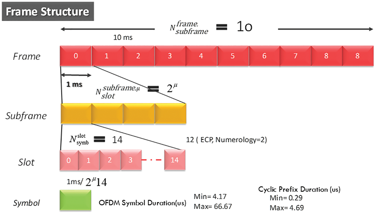
Figure 1: 5G Frame structure
Each sub-frame is again divided as slots and each sub-frame has 14 slots [8]. The slot is further divided as symbols, which constitutes a very little space in the entire framework of 10 ms. The mathematical definition for the frame is given as
When the sub carrier spacing μ = 2, then
1 symbol = 10 sub-symbols
1 sub-symbols = 2 μ spacing = 2 spaces
1 space = 14 OFDM images
Thereby the symbol = 2*10*14 = 280 OFDM images [9]. Thus the OFDM images are adaptive for the 5G New Radio time frame and hence significantly show up with high frequencies with very short symbols i.e., millimeter waves. For example, the 15 kHz symbol in LTE is equivalent to the 2 μ*15 kHz in the 5G New Radio time frame [10]. The numerology support for the 5G New Radio frame is shown in Tab. 1 as below and The subcarrier spacing for various frequencies is represented pictorially mentioned in Fig. 2.
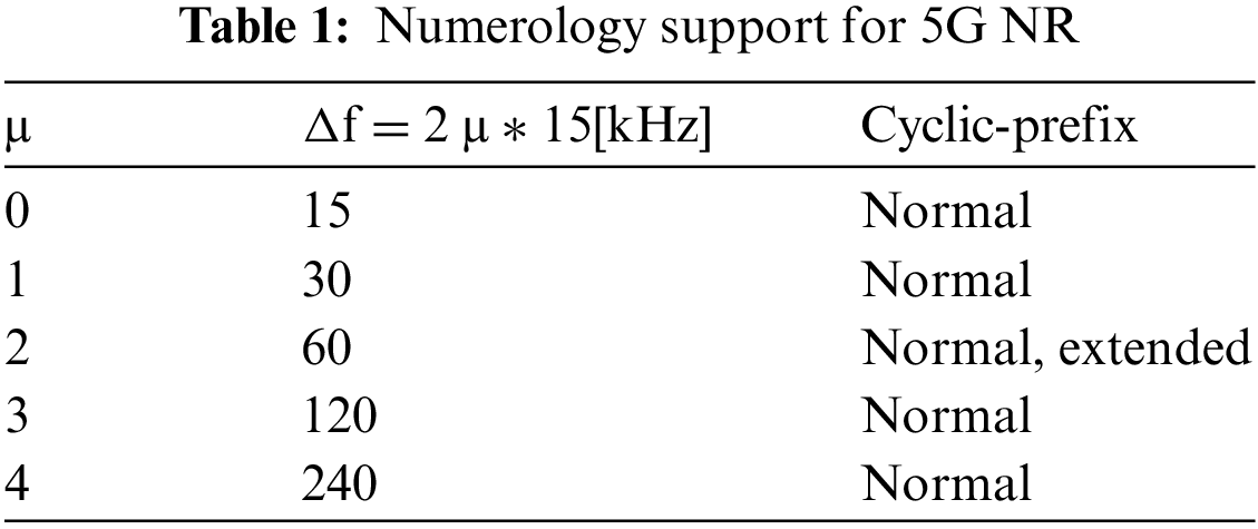

Figure 2: Sub carrier spacing of 5G NR
The overview of the Radio Protocol in the 5G New Radio frame structure is described in this section.
The Physical Layer is the top layer in the 5G New Radio hierarchy. It comprises of MAC layer and Resource Layer. The MAC is provided with the transport channel which takes the responsibility of logical channel allocation and the shipping channel is provided with the radio resource channel [11]. The rate of data transferred will purely depend on the logical channel specs.
The MAC layer is responsible for the controlling of the hardware which is associated with wired, wireless, and optical communications [12,13]. The MAC layer has a tract of vital signals such as clock and reset. It generally operated at a frequency of 20 MHz and is interfaced with the CRC. Fig. 3 shows the Physical Layer frame of the Radio protocol.

Figure 3: Radio protocol architecture around the physical layer
The beam management for the synchronization in 5G New Radio will provide access to the user to connect with the gNB in the physical layer and establish the radio link in the physical layer for the UE communication [8]. The beam management constitutes of these operations sweeping, determination, measurement, and reporting of the beam. These operations are defined in Fig. 4.

Figure 4: 5G NR synchronization procedure
The initial access to the signal is carried by the primary synchronization block and then it is further handed over to the secondary synchronization block [14]. The obtained signal is considered as the final cell ID of the transmitted signal. The New Radio Primary Synchronization Signal (NR-PSS) is detected to acquire the symbol timing, sector cell index and New Radio Secondary Synchronization Signal (NR-SSS) is used for detecting cell sector index. NR-SSS can be identified only after successful detection of the NR-PSS. Down Link (DL) synchronization performance depends on NR-PSS detection at User Equipment (UE). The primary and secondary synchronizations are explained in detail in the next section.
where
The user equipment determines PCI bunch quantity

Figure 5: Procedure for determining PCI (Physical Cell Identity)
5.1 Primary Synchronization Signal
PSS is constantly positioned in the principal OFDM image of synchronization block [15] and possesses subcarriers with lists from 57 to 183 as proven in Fig. 6.

Figure 6: 5G NR Time-Frequency structure of SSB
The PSS block is configured with the correlation modules followed with the PSS maximum finder [16] and finally the

Figure 7: 5G NR Primary synchronization signal detection top block
For NR-PSS detection: The matched filters are used for autocorrelation. The M-sequence is used for constant coefficients for taps in the matched filters.
M-sequence: The M-sequence is the longest non-repeating sequence for the taps of matched filters in PSS. A periodic sequence of symbols is generated by a linear feedback shift register whose feedback coefficients form a primitive polynomial.
The Primary SS are depicted as follows.
Discrete Prolate Spheroidal Sequences-DPSS(n) = 1−2x(m)
0 ≤ n < 127
Where
x(i + 7) = (x(i+4) + x(i)) mod 2
And initial state
[x(6) x(5) x(4) x(3) x(2) x(1) x(0)] = [1 1 1 0 1 1 0]
The maximum correlation signal out of three matched filters will be calculated and the corresponding number is treated as
5.2 Secondary Synchronization Signal
SSS is consistently positioned inside the third OFDM image of synchronization block [17] (like PSS) and involves subcarriers with files from 57 to 183 as appeared in Fig. 8.

Figure 8: 5G NR Secondary synchronization signal detection algorithm
Be that as it may, the 5G NR Primary SS comprises of one among three 336 127-images gold sequence and is assigned at the 3rd image of every Synchronization Signal Block (SSB), and on 127 sub-carriers as shown in Fig. 9. The 336 possible Gold sequence for the Secondary SS [18] are portrayed as follows.

Figure 9: 5G NR Secondary synchronization signal detection top block
m0 = 15[
m1 =
0 ≤ n < 127 Where
X0(|i + 7|) = (X0 (|i + 4|) + X0 (i)) modulus 2
X1(|i + 7|) = (X1 (|i + 1|) + X1 (i)) modulus 2
And Initial state:
[X1(0) X1(1) X1(2) X1(3) X1(4) X1(5) X1(6)] = [1 0 0 0 0 0 0]
[X0(0) X0(1) X0(2) X0(3) X0(4) X0(5) X0(6)] = [1 0 0 0 0 0 0]
The simulation results for the proposed synchronization blocks i.e., primary synchronization and secondary synchronization is shown in Figs. 10–15 below.

Figure 10: 5G NR PSS detection top level schematic block

Figure 11: 5G NR SSS detection top level schematic block

Figure 12: 5G NR PSS detection gate level schematic

Figure 13: 5G NR SSS detection gate level schematic

Figure 14: 5G NR PSS detection output waveform

Figure 15: 5G NR PSS & SSS implemented design
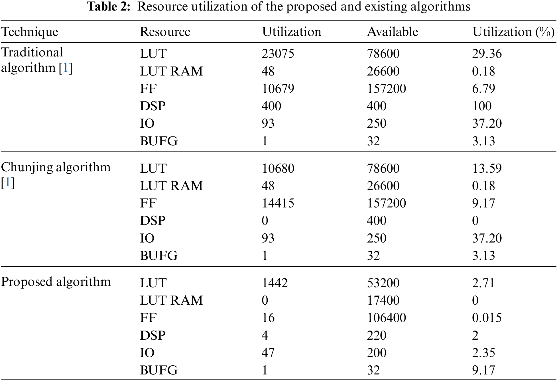
Implementation manner is accomplished through using FPGA Zynq-7000 series Zed-board. The utilization reports of post-synthesis of design are given as shown below. The Primary SS Synchronizer and Secondary SS Synchronizer module utilization summary is detailed with respective summary reports. The resource utilization summary for the existing algorithm [1] and the proposed algorithm is tabulated as shown below in Tab. 2.
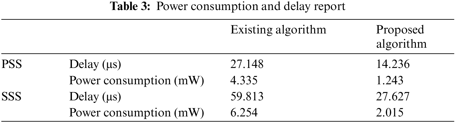
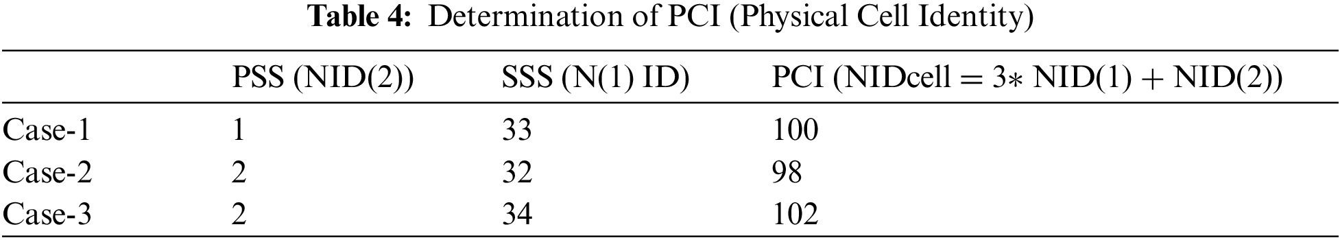
The reports of power consumption and delay are listed in the Tab. 3 as compared with the existing algorithm [18]. Determination of PCI (Physical Cell Identity) mentioned in Tab. 4.
The values obtained by the PSS and SSS correlation [19–21] by considering different cell IDs are plotted graphically as shown below in Figs. 16–21.

Figure 16: PSS Correlation vs. Frequency offset (PCI=100)

Figure 17: SSS Correlation vs. Frequency offset (PCI=100)

Figure 18: . PSS Correlation vs. Frequency offset (PCI=98)

Figure 19: SSS Correlation vs. Frequency offset (PCI=98)

Figure 20: PSS Correlation vs. Frequency offset (PCI=102)

Figure 21: SSS Correlation vs. Frequency offset (PCI=102)
Case 1: Calculation of Physical Cell Id (PCI)
NID cell = 3*
= 3(33) + 1
= 100
Case 2: Calculation of Physical Cell Id(PCI) [22]
NIDcell = 3*
= 3(32) + 2
= 98
Case 3: Calculation of Physical Cell Id(PCI)
NIDcell = 3*
= 3(34) + 2
= 102
This suggested design of the Primary SS and Secondary SS Synchronizer for 5G NR base-band receiver were validated, verified, and implemented efficiently on an FPGA Zynq-7000 series Zed board. The results show that the proposed design ensures the determination of cell identity effectively by incorporation of the proposed technique of primary and secondary synchronization blocks. Also, the hardware utilization is reduced by 63.7%, power consumption is reduced by 31.2%, and is operated with high speed with a minimum of 200 MHz and a maximum of GHz clock rates.
Funding Statement: The authors received no specific funding for this study.
Conflicts of Interest: The authors declare that they have no conflicts of interest to report regarding the present study.
1. K. Manolakis, D. M. G. Estevez, V. Jungnickel, X. Wen and C. Drewes, “A closed concept for synchronization and cell search in 3GPP LTE systems,” in IEEE Wireless Communications and Networking Conf., Budapest, Hungary, pp. 1–6, 2009. [Google Scholar]
2. H. Chunjing and Y. Zhang, “5G nr primary synchronization signal detection with low hardware resource occupancy,” in IEEE/CIC Int. Conf. on Communications in China (ICCC), Beijing, China, pp. 304–308, 2018. [Google Scholar]
3. S. Parkvall, “Evolved universal terrestrial radio access (E-UTRA); Physical channels and modulation,” 3GPP TS 36.211, Technical Specification Group Radio Access Network, Evolved Universal Terrestrial Radio Access (E-UTRARev. 10.0.0, 2011. [Online]. Available: https://www.3gpp.org/dynareport/36211.htm. [Google Scholar]
4. Y. Kryukov, D. Pokamestov and E. Rogozhnikov, “Cell search and synchronization in 5G NR,” ITM Web of Conferences, vol. 30, pp. 1–4, 2019. [Google Scholar]
5. D. Chu, “Polyphase codes with good periodic correlation properties,” IEEE Transactions on Information Theory, vol. 18, no. 4, pp. 531–532, 1972. [Google Scholar]
6. B. M. Popovic and F. Berggren, “Primary synchronization signal in E-UTRA,” in IEEE 10th Int. Symp. on Spread Spectrum Techniques and Applications, Bologna, Italy, pp. 426–430, 2008. [Google Scholar]
7. M. Morelli and M. Moretti, “A robust maximum likelihood scheme for PSS detection and integer frequency offset a recovery in LTE systems,” IEEE Transactions on Wireless Communications, vol. 15, no. 2, pp. 1353–1363, 2016. [Google Scholar]
8. A. El-Keyi, O. Uereten, T. Yensen and H. Yanikomeroglu, “Lte physical layer identity detection in the presence of jamming,” in Proc. of IEEE 86th Vehicular Technology Conf. (VTC-Fall), Toronto, Canada, pp. 1–6, 2017. [Google Scholar]
9. S. Kiruthika and A. Vimalastarbino, “Design and analysis of FIR filters using low power multiplier and full adder cells,” in IEEE Int. Conf. on Electrical, Instrumentation, and Communication Engineering (ICEICE), Karur, India, pp. 1–5, 2017. [Google Scholar]
10. A. Shimura, M. Sawahashi, S. Nagata and Y. Kishiyama, “Initial cell search method with MLD based frequency offset estimation in LTE heterogeneous networks,” in IEEE 86th Vehicular Technology Conf. (VTC-Fall), Toronto, ON, Canada, pp. 1–5, 2017. [Google Scholar]
11. D. Weiler, “3rd generation partnership project (3GPP) evolved universal terrestrial radio access (E-UTRA) Physical channels and modulation,” Sophia-antipolis cedex, France, 3GPP TS 36.211 v8.9.0, 2010, [Online]. Available: https://www.etsi.org/deliver/etsi_TS/136200_136299/136211/. [Google Scholar]
12. D. Astely, E. Dahlman, A. Furuskar, Y. Jading, M. Lindstrom et al., “LTE: The evolution of mobile broadband,” IEEE Communications Magazine, vol. 47, no. 4, pp. 44–51, 2009. [Google Scholar]
13. R. Buvaneswaran and S. Srikanth, “Cell search and uplink synchronization in LTE,” International Journal of Scientific & Engineering Research, vol. 4, no. 5, pp. 1011–1016, 2013. [Google Scholar]
14. V. Paliwal and I. Lambadaris, “Cell search procedures in LTE systems,” EURASIP Journal on Wireless Communications and Networking, vol. 4, no. 1, pp. 1–6, 2017. [Google Scholar]
15. A. Omri, M. Shaqfeh, A. M. Ali and H. Alnuweiri, “Synchronization procedure in 5G NR systems,” IEEE Access, vol. 7, pp. 41286–41295, 2019. [Google Scholar]
16. A. Golnari, G. Sharifan, Y. Amini and M. Shabany, “A low complexity architecture for the cell search applied to the LTE systems,” in 19th IEEE Int. Conf. on Electronics, Circuits, and Systems (ICECS 2012), Seville, Spain, pp. 300–303, 2012. [Google Scholar]
17. F. Soewito, “FPGA based timing synchronizer for LTE 4G receiver,” Bachelor’s Thesis, Bandung Institute of Technology, Bandung, Indonesia, 2015. [Google Scholar]
18. J. Kurniawan, N. Ahmadi and T. Adiono, “Architecture and FPGA implementation of LTE PSS and SSS synchronizer,” in Proc. ISPACS (November 2015), Nusa Dua, Indonesia, pp. 235–240, 2015. [Google Scholar]
19. A. N. Gaber, L. D. Khalaf, A. M. Mustafa and J. Yemen, “Synchronization and cell search algorithms in 3GPP long term evolution systems (fdd mode),” WSEAS Transactions on Communications, vol. 11, no. 2, pp. 70–81, 2012. [Google Scholar]
20. M. Lienliou and T. Darchiueh, “A low-power digital matched filter for direct-sequence spread-spectrum signal acquisition,” IEEE Journal of Solid-State Circuits, vol. 36, no. 6, pp. 933–943, 2001. [Google Scholar]
21. A. J. Viterbi, “Principles of spread spectrum communication,” in Wireless Communication Series, CDMA. Addison-Wesley, Boston, pp. 1–272, 1995, [Online], Available: https://www.wiley.com/en-al/Spread+Spectrum+and+CDMA%3A+Principles+and+Applications-p-9780470091791. [Google Scholar]
22. S. Srikanth, M. Pandian and X. Fernando, “Orthogonal frequency division multiple access in WiMAX and LTE: A comparison,” IEEE Communications Magazine, vol. 50, no. 9, pp. 153–161, 2012. [Google Scholar]
 | This work is licensed under a Creative Commons Attribution 4.0 International License, which permits unrestricted use, distribution, and reproduction in any medium, provided the original work is properly cited. |