DOI:10.32604/cmc.2022.022921
| Computers, Materials & Continua DOI:10.32604/cmc.2022.022921 | |
| Article |
Control of Linear Servo Carts with Integral-Based Disturbance Rejection
1Department of Electrical and Computer Engineering (ECE), King Abdulaziz University, 55, 21589, Saudi Arabia
2Center of Excellence in Intelligent Engineering Systems (CEIES), King Abdulaziz University, 65, 21589, Saudi Arabia
3Electrical and Computer Engineering, TN, 38505, United States
4Computer and Information Systems, Umm Al-Qura University, Makkah, Saudi Arabia
*Corresponding Author: Ibrahim M. Mehedi. Email: imehedi@kau.edu.sa
Received: 23 August 2021; Accepted: 18 February 2022
Abstract: This paper describes a system designed for linear servo cart systems that employs an integral-based Linear Active Disturbance Rejection Control (ILADRC) scheme to detect and respond to disturbances. The upgrade in this control technique provides extensive immunity to uncertainties, attenuation, internal disturbances, and external sources of noise. The fundamental technology base of LADRC is Extended State Observer (ESO). LADRC, when combined with Integral action, becomes a hybrid control technique, namely ILADRC. Setpoint tracking is based on Bode’s Ideal Transfer Function (BITF) in this proposed ILADRC technique. This proves to be a very robust and appropriate pole placement scheme. The proposed LSC system has experimented with the hybrid ILADRC technique plotted the results. From the results, it is evident that the proposed ILADRC scheme enhances the robustness of the LSC system with remarkable disturbance rejection. Furthermore, the results of a linear quadratic regulator (LQR) and ILADRC schemes are comparatively analyzed. This analysis deduced the improved performance of ILADRC over the LQR control scheme.
Keywords: Pole placement; ADRC; Active disturbance rejection; robust control; linear servo cart system
As industrial systems become more complex, their analysis and control become even more complex, thus increasing the complexity. Recent research focuses on designing control systems robust to uncertainties that are internal like dynamics or external like disturbances. Some advancements in the research mentioned above are discussed as follows. First is the scheme to control the external uncertainties of linear/nonlinear systems using sliding mode control [1,2]. Next comes the scheme to control parameter uncertainties on interval systems using linear matrix inequalities [3,4]. Another method uses data-driven control to control online parameter identification and ultra-local models [5,6]. Finally, control of generalized disturbance, which controls both internal and external disturbances, is the ESO scheme proposed in [7,8]. This method cancels the generalized disturbance by deploying a feedback loop. These research advancements provide good enough samples for experimental and simulation results [9,10].
It is concluded that when parametric uncertainties and system nonlinearities are present, linear control schemes such as linear quadratic regulators (LQRs) and proportional integral derivatives (PIDs) exhibit instability. [11]. This raised the need for nonlinear control schemes like Fuzzy Logic control [12,13], and Neural Networks control [14], which were effective with improved convergence. Control of sliding mode systems (SMC) [15–17] is an effective and robust control method widely regarded for its ability to filter out disturbances. Nonlinear Dynamic Inversion (NDI) is another robust control technique competent in eliminating nonlinearities [18]. In order to effectively control the speed and position of a linear servo-cart system, state space-based fractional order integral controller is a powerful system technique [19–24].
LADRC control method solves both the setpoint tracking (SPT) and disturbance rejection (DR) problems more effectively than the standard method by accepting the disturbance as a variable [25]. The integer integrator is implemented to utilize this LADRC control for integral-based controllers. For such a controller, calculating the parameters of a non-integer fractional-order operator is very tough to achieve. This could be solved by the pole replacement method; however, the solution is still unsure [26]. The uncertainty is overcome by using augmented models for this controller [27,28]. State space-based fractional order integral controller is an augmented system technique for effective control of speed and position of a linear servo-cart system [25–27]. Calculating the control law parameters is then possible with a suitable pole placement. In addition, two aspects must be considered in this procedure. A first problem is that the CL reference model does not calculate the control law’s non-integer order.
In addition, it must be logical. Secondly, the specific polynomial that corresponds to the augmented model has a high order. Finally, this proposed work plays a significant role in the following:
• Introduces the BITF model to control systems using integral-based controllers by imposing iso-dumping property in the CL response.
• Proposes the LDARC control for necessary action with the SPT loop.
• Contributes theoretically in designing a new control method for SPT controller using BITF.
• Validates the theoretical contribution by simulation results, especially concerning SPT controller gain variations, to robustizing the control structure.
• Implements the proposed ILADRC controller experimentally on a linear servo cart system. It is also more robust than the existing methods based on the results obtained.
Although there are many works on dynamic inversion-based controller algorithms, most of them integrated it with different other techniques and applied them to various applications. None of the investigations integrates with fractional-order control techniques as in our paper.
When designing a controller, the stability of the dynamical systems is the essential criterion. It is a well-known fact that model uncertainties and disturbances could cause instability to the system. For this reason, studies of new or improved controllers have continuously been an active research area. A linear servo cart system with a DC motor connected to a rack and cart is described in this article as an example of a dynamical system. The Fig. 1 shows the dynamical system described in this article as a linear servo cart. As the mass of the cart is one of the critical parameters in the system’s dynamic, applying loads with different masses to the cart could change the system’s dynamic. A practical example is when an additional load is applied to the cart when it is already in the desired position. The cart will oscillate because a bad controller will not compensate for changes in dynamic.
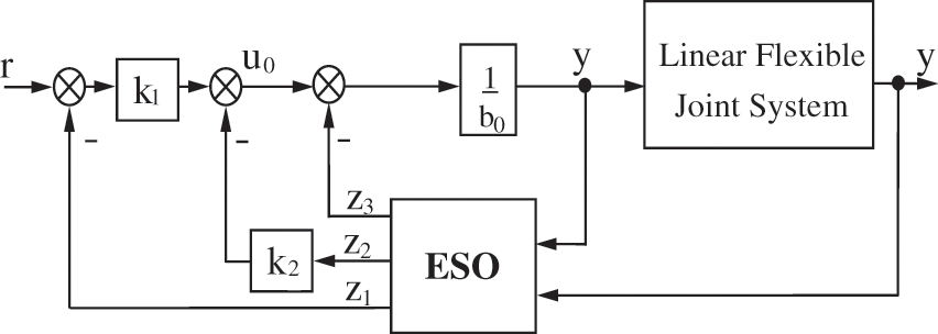
Figure 1: Standard structure of LADRC
There are many types of controllers introduced to overcome the mentioned issues. The RGDI controller has shown good setpoint tracking performance and robustness in dealing with system uncertainties in a similar application. However, there are still some tracking errors that we believe our proposed invention could improve, and there was also no proof if the RGDI can still perform well when disturbances are injected. Therefore, in this article, we will add a test where a disturbance is injected at a steady state and compare the performance of RGDI with our proposed invention.
The standard LADRC formulation for linear integer order systems does not require the control of the entire model. According to this method, the model’s gain and degree are the determining factors. For a second-order model, the controlled scheme is as follows:
Where
By using an ESO, the LADRC method estimates the unknown. In cases where
where:
and
ESO is structured as follows
where,
Asymptotically stable
Eq. (1) becomes two cascaded integer-order integral operators without considering the estimated error,
As a standard solution to setpoint tracking, state feedback is used. Therefore, the control law
LADRC’s standard structure is shown in Fig. 1. The gain vectors to be designed for this system are the Ko for the controller, and the L for the ESO. The method that is generally used to design these gain vectors. The observer and controller bandwidths are determined by two parameters,
The main point to bear in mind is that derivatives of non-integer order have different meanings, and that these definitions are not always equivalent. In this paper, we propose a control system based on a LADRC and integer-ordered necessary actions. The present study has combined fractional integrals with another technique. Specifically, its main objective is to enhance the performance of the standard LADRC for fuzzy systems, specifically regarding the effect of external disturbances. It was shown in Fig. 2 how the proposed technique works.
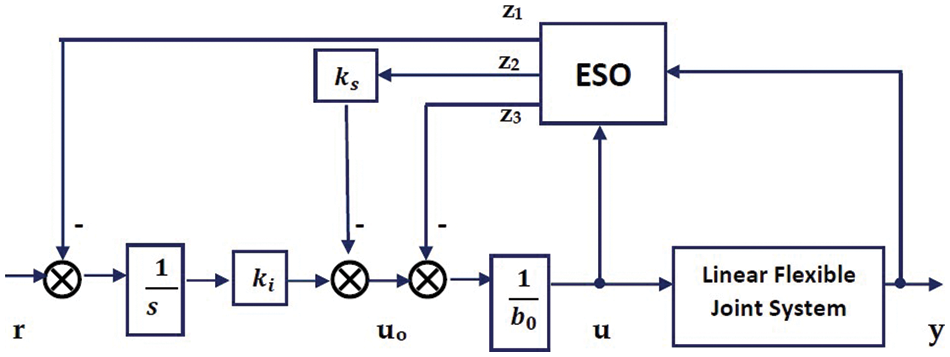
Figure 2: Integral control structure of LADRC
According to the state feedback Ks, the CL characteristic polynomial’s n poles may be placed at their discretion. Eq. (9), in order to impose on the closed-loop Bode’s ideal transfer function, is coupled with the fractional integration gain, Ki. Then the LADRC structure may be strengthened in terms of the open-loop gain setpoint. In this case, Eq. (3) indicates the ESO. Based on this, we have the following control signal:
where
The following would be a progression of methods that can be used to determine the coefficient of state feedback Ks2, the coefficient Ki associated with the fractional integrator of Eq. (8), and finally the non-integer order
This corresponds to the open loop
when
Eq. (6) gives the equation for a closed-loop system with a control plant, and Eq. (8) gives the equation for the control law:
The following is a simple way to write it
The transfer function in Eq. (9) has to have exactly the same value as the reference model in this equation.
Remark:
5 Mathematical Modeling of LSC System
Fig. 3 depicts a typical LSC system. The LSC system consists of a DC motor and the gearbox, whose schematic diagram is shown in Fig. 4. M
where,
with the following factors,
kg - the ratio between the gears,
km- constant of the back-emf,
rmp - the motor pinion radius, and
Rm - motor resistance.
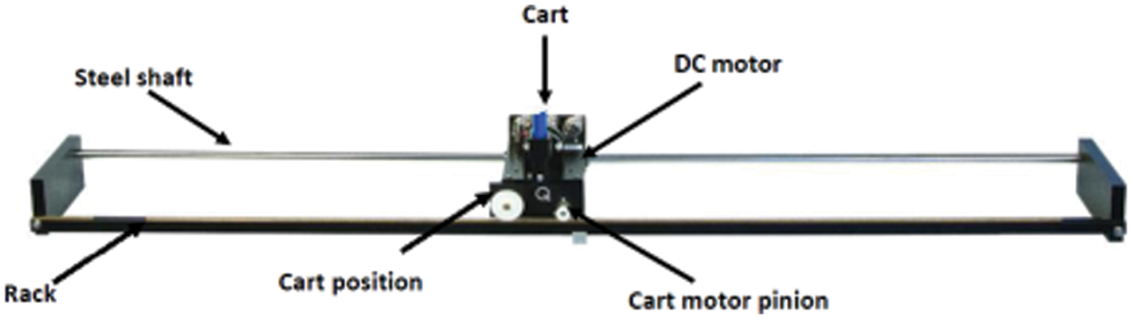
Figure 3: Cart system with linear servos
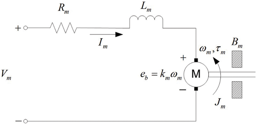
Figure 4: LSC system diagram
As a result of its low value, motor inductance is ignored.
The driving force,
where vm is the voltage applied to the actuator, and Am represents the gain of the actuator, obtained as
The steady-state gain and time constant are derived from the above transfer function as
Eq. (15) does not account for inertial forces due to motor armature as described above. It is important to note that if this force is taken into consideration, it will only result in change to the time constant parameter, and not to the steady-state gain, such that
with equivalent inertia term calculated as follows:
The voltage and cart position transfer function can be computed through the cascading of an integrator (1/s) with the speed transfer function as,
6 Linear Servo Cart Implementation
An example of LADRC control scheme that validates the performance of the proposed Integral based LADRC control scheme consists of a linear servo cart system, which consists of two carts sliding on a track and driving one of them using a DC motor. This system has been found to be an interesting example of a LADRC control scheme that utilizes a linear servo motor to drive one of the carts. Due to the interaction between two systems, the modeling of this system is complex. During testing, determining the cart’s position was the objective, and the vibration was considered a permanent disturbance. As shown in Fig. 3, a linear servo cart system (LSC) is used. Fig. 4 illustrates this with a mass system in which
To demonstrate the LQR control scheme and compare ILADRC’s performance to the standard LQR structure, we use the linear servo cart system described above. A linear servo cart system is an interesting example since a DC motor drives a cart sliding on a track. Controlling the cart’s position is the goal, and the uncertainty is regarded as a permanent disturbance.
Computer simulations are performed on a linearized Linear Servo Cart (LSC) system to authenticate the controller’s performance to evaluate the real-time performance. In Simulink/Matlab, we create a simulation environment with a simulation time of 5 s in order to analyze numerically the controller performance. The square wave profile having an amplitude of 100 mm with a frequency of 0.66 Hz is commanded as a reference input command to the LSC system. The linear displacement and speed response and the controlled voltage to a reference square wave command are shown in simulation results.
The simulation is carried out by providing a square wave linear displacement profile with a magnitude of ±10 cm with a frequency of 0.1 Hz. Fig. 5 compares different control approaches for a square input command. The performance indices in terms of rising time, settling time, and overshoot achieved through ILADRC control are better than its counterpart control strategies. The more significant overshoot and chattering phenomenon are visible in the LQR response. In contrast, no overshoot is observed in ILADRC response with faster convergence towards the reference command in the transient phase followed by smooth, steady-state performance. The time responses of the linear speed and corresponding controlled voltages undersupplied capacity are shown in Figs. 5b and 5c, respectively.
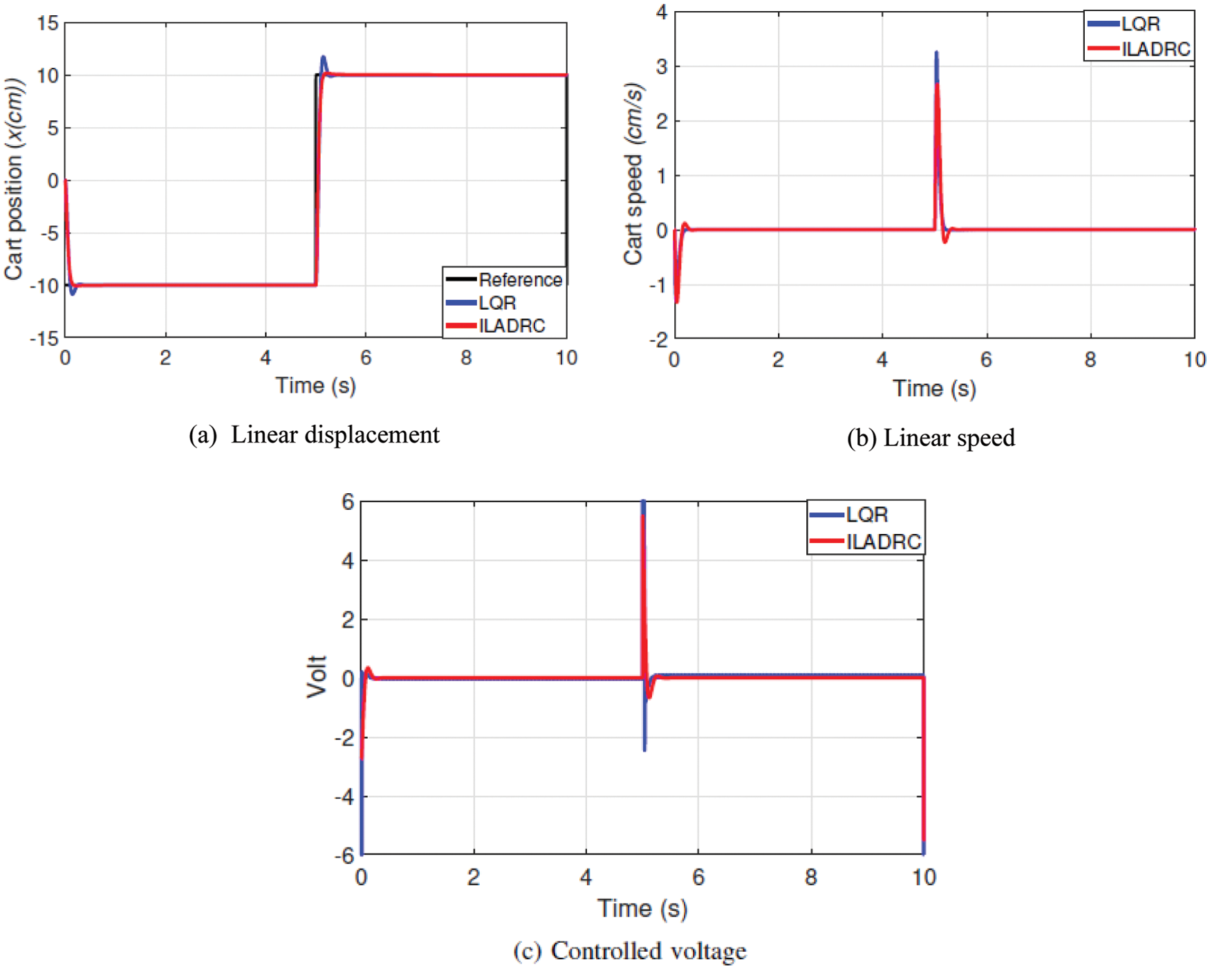
Figure 5: Square-wave tracking
The simulation was performed by considering a sawtooth profile as a reference input to the LSC system to visualize the performance of ILARDC with traditional LQR for robustness and parametric uncertainties. The evolution of the linear position and speed responses and controlled voltages are illustrated in Fig. 6. The time response curves of linear displacement against the sawtooth profile are shown in Fig. 6a. The results depict improved performance of ILADRC control as compared with LQR, by keeping the linear servo cart closer to the desired reference input command. The time-domain speed curves are shown in Fig. 6b. Finally, the controlled voltages of two control approaches are presented in Fig. 6c, in which the undesirable high value is observed in the controlled voltages generated by LQR, whereas these are significantly reduced by proposed ILADRC control. Therefore, from the results, it is concluded that ILADRC control demonstrates improved tracking control and better performance.
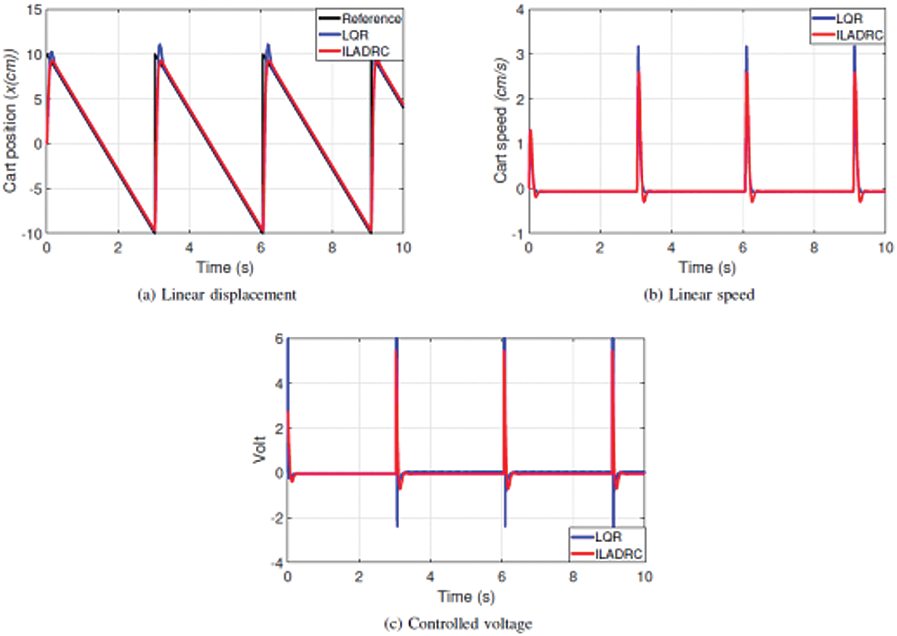
Figure 6: Results: Saw profile
Servo cart systems play a vital role in a number of automated systems because of their displacement and speed control. In this work, an ILADRC control technique is developed for displacement and speed control of linear servo carts. Several speed and position control technique-based related work was initially studied and analyzed. It is proposed to control a minimum phase-stable system using a LADRC structure with an integrated action (ILADRC). This contribution consists a novel design method is proposed for the ILADRC scheme based on the BITF. As elaborated in the previous section, a novel design method is proposed for the SPT controller. A critical contribution to the design of the LADRC control scheme is to use it from a practical point of view. Using results obtained from experiments on the linear servo cart system (LSC), the effectiveness of the proposed ILADRC scheme is illustrated. Results show improvements in robustness due to the rejection of disturbances in ILADRC scheme. In addition, results are compared between the integral-based LADRC and the traditional LQR schemes which are based on statistical methods.
Acknowledgement: The authors extend their appreciation to the Deputyship for Research & Innovation, Ministry of Education in Saudi Arabia for funding this research work through the project number (IFPRC-023-135-2020) and King Abdulaziz University, DSR, Jeddah, Saudi Arabia.
Funding Statement: This research work was funded by Deputyship for Research & Innovation, Ministry of Education in Saudi Arabia under grant no (IFPRC-023-135-2020).
Conflicts of Interest: The authors declare that they have no conflicts of interest to report regarding the present study.
1. Y. Liu, X. Yan, F. Yan, Z. Xu and W. Shang, “Sliding-mode PID control of UAV based on particle swarm parameter tuning,” Computers, Materials & Continua, vol. 63, no. 1, pp. 469–487, 2020. [Google Scholar]
2. Z. Sun, Y. Bi, S. Chen, B. Hu, F. Xiang et al., “Designing and optimization of fuzzy sliding mode controller for nonlinear systems,” Computers, Materials & Continua, vol. 61, no. 1, pp. 119–128, 2019. [Google Scholar]
3. K. A. Barbosa, C. E. De Souza and A. Trofino, “Robust H2 filtering for uncertain linear systems: LMI based methods with parametric Lyapunov functions,” Systems and Control Letters, vol. 54, no. 3, pp. 251–262, 2005. [Google Scholar]
4. Y. H. Lan and Y. Zhou, “LMI-based robust control of fractional-order uncertain linear systems,” Computers & Mathematics with Applications, vol. 62, no. 3, pp. 1460–1471, 2011. [Google Scholar]
5. Z. S. Hou and Z. Wang, “From model-based control to data-driven control: Survey, classification and perspective,” Information Sciences, vol. 235, no. 1, pp. 3–35, 2013. [Google Scholar]
6. M. Fliess and C. Join, “Model-free control,” International Journal of Control, vol. 86, no. 12, pp. 2228–2252, 2013. [Google Scholar]
7. J. Han, “Active disturbance rejection controller and its applications (in Chinese),” Control Decision, vol. 13, no. 1, pp. 19–23, 1998. [Google Scholar]
8. J. Han, “From PID to active disturbance rejection control,” IEEE Transactions on Industrial Electronics, vol. 56, no. 3, pp. 900–906, 2009. [Google Scholar]
9. B. Guo and F. Jin, “Sliding mode and active disturbance rejection control to stabilization of one-dimensional anti-stable wave equations subject to disturbance in boundary input,” IEEE Transactions on Automatic Control, vol. 58, no. 5, pp. 1269–1274, 2013. [Google Scholar]
10. H. Xing, J. Jeon, K. Park and I. K. Oh, “Active disturbance rejection control for precise position tracking of ionic polymer-metal composite actuators,” IEEE/ASME Transactions on Mechatronics, vol. 18, no. 1, pp. 86–95, 2013. [Google Scholar]
11. Z. Y. Nie, Y. J. Ma, Q. G. Wang and D. Guo, “Guaranteed-cost active disturbance rejection control for uncertain systems with an integral controller,” International Journal of Systems Science, vol. 49, no. 9, pp. 2012–2024, 2018. [Google Scholar]
12. M. Bettayeb, C. Boussalem, R. Mansouri and U. M. Al-Saggaf, “Stabilization of an inverted pendulum-cart system by fractional PI-state feedback,” ISA Transactions, vol. 53, no. 2, pp. 508–516, 2014. [Google Scholar]
13. G. Rohith, “Fractional power rate reaching law for augmented sliding mode performance,” Journal of the Franklin Institute, vol. 358, no. 1, pp. 856–876, 2021. [Google Scholar]
14. I. Tejado, A. Djari and B. M. Vinagre, “Two strategies for fractional sliding mode control of integer order systems by system augmentation: Application to a servomotor,” IFAC-PapersOnLine, vol. 50, no. 1, pp. 8103–8108, 2017. [Google Scholar]
15. I. M. Mehedi, U. M. Al-Saggaf, R. Mansouri and M. Bettayeb, “Stabilization of a double inverted rotary pendulum through fractional order integral control scheme,” International Journal of Advanced Robotic Systems, vol. 16, no. 4, pp. 1–9, 2019. [Google Scholar]
16. C. Farges, M. Moze and J. Sabatier, “Pseudo-state feedback stabilization of commensurate fractional order systems,” Automatica, vol. 46, no. 10, pp. 1730–1734, 2010. [Google Scholar]
17. B. Gao, X. Liu, X. Wu, S. Li, Z. Lan et al., “Stability of nonlinear feedback shift registers with periodic input,” Computers, Materials & Continua, vol. 62, no. 2, pp. 833–847, 2020. [Google Scholar]
18. U. M. Al-Saggaf, I. M. Mehedi, M. Bettayeb and R. Mansouri, “Fractional-order controller design for a heat flow process,” Proceedings of the Institution of Mechanical Engineers, Part I: Journal of Systems and Control Engineering, vol. 230, no. 7, pp. 680–691, 2016. [Google Scholar]
19. U. M. Al-Saggaf, I. M. Mehedi, R. Mansouri and M. Bettayeb, “State feedback with fractional integral control design based on the bode’s ideal transfer function,” International Journal of Systems Science, vol. 47, no. 1, pp. 149–161, 2016. [Google Scholar]
20. U. M. Al-Saggaf, R. Mansouri, M. Bettayeb, I. M. Mehedi and K. Munawar, “Robustness improvement of the fractional-order LADRC scheme for integer high-order system,” IEEE Transactions on Industrial Electronics, vol. 68, no. 9, pp. 8572–8581, 2021. [Google Scholar]
21. C. Tian, P. Yan and Z. Gao, “Data-driven iterative tuning based active disturbance rejection control for piezoelectric nano-positioners,” Mechatronics, vol. 65, no. 5, pp. 102321, 2020. [Google Scholar]
22. H. M. Fahad and A. Fernandez, “Operational calculus for caputo fractional calculus with respect to functions and the associated fractional differential equations,” Applied Mathematics and Computation, vol. 409, pp. 126400, 2021. https://doi.org/10.1016/j.amc.2021.126400. [Google Scholar]
23. A. Tepljakov, B. B. Alagoz, C. Yeroglu, E. Gonzalez, S. H. H. Nia et al., “FOPID controllers and their industrial applications: A survey of recent results,” IFAC-PapersOnLine, vol. 51, no. 4, pp. 25–30, 2018. [Google Scholar]
24. G. G. Lublovary and T. Insperger, “Transient stabilization of an inverted pendulum with digital control,” IFAC-PapersOnLine, vol. 51, no. 22, pp. 197–202, 2018. [Google Scholar]
25. H. Rezk, M. M. Alhato, M. Alhaider and S. Bouallègue, “Fractional-order control of a wind turbine using manta ray foraging optimization,” Computers, Materials & Continua, vol. 68, no. 1, pp. 185–199, 2021. [Google Scholar]
26. I. M. Mehedi, R. Mansouri, U. M. Al-Saggaf and M. Bettayeb, “Fractional order linear active disturbance rejection control for linear flexible joint system,” CMC-Computers, Materials & Continua, vol. 70, no. 3, pp. 5133–5142, 2022. [Google Scholar]
27. I. M. Mehedi, “State feedback based fractional order control scheme for linear servo cart system,” Journal of Vibroengineering, vol. 20, no. 1, pp. 782–792, 2018. [Google Scholar]
28. J. Apkarian, H. Lacheray and P. Martin, Linear servo cart system-workbook. Canada: Quanser Inc, 2012. [Google Scholar]
 | This work is licensed under a Creative Commons Attribution 4.0 International License, which permits unrestricted use, distribution, and reproduction in any medium, provided the original work is properly cited. |