DOI:10.32604/cmc.2022.024918
| Computers, Materials & Continua DOI:10.32604/cmc.2022.024918 | |
| Article |
Analyzing and Enabling the Harmonious Coexistence of Heterogeneous Industrial Wireless Networks
1Department of Computer Science, National University of Computer and Emerging Sciences, Islamabad, Chiniot-Faisalabad Campus, Chiniot, 35400, Pakistan
2Faculty of General Education, Kangnam University, Korea
*Corresponding Author: Ga-Young Kim. Email: dolga2000@kangnam.ac.kr
Received: 04 November 2021; Accepted: 07 January 2022
Abstract: Nowadays multiple wireless communication systems operate in industrial environments side by side. In such an environment performance of one wireless network can be degraded by the collocated hostile wireless network having higher transmission power or higher carrier sensing threshold. Unlike the previous research works which considered IEEE 802.15.4 for the Industrial Wireless communication systems (iWCS) this paper examines the coexistence of IEEE 802.11 based iWCS used for delay-stringent communication in process automation and gWLAN (general-purpose WLAN) used for non-real time communication. In this paper, we present a Markov chain-based performance model that described the transmission failure of iWCS due to geographical collision with gWLAN. The presented analytic model accurately determines throughput, packet transaction delay, and packet loss probability of iWCS when it is collocated with gWLAN. The results of the Markov model match more than 90% with our simulation results. Furthermore, we proposed an adaptive transmission power control technique for iWCS to overcome the potential interferences caused by the gWLAN transmissions. The simulation results show that the proposed technique significantly improves iWCS performance in terms of throughput, packet transaction, and cycle period reduction. Moreover, it enables the industrial network for the use of delay critical applications in the presence of gWLAN without affecting its performance.
Keywords: Round robin; distributed coordination function; interference; csma; ieee 802.11; factory automation; process automation
The recent advances in wireless networks have motivated the research community to adopt the high speed wireless technology for the industrial automation which is essential to the implementation of Industry 4.0 [1]. In industrial automation, wireless technology is used to cope with the urgent requirements of the real-time control communications. Real-time control communication requires low-network latency, reliability and deterministic sequence of transmissions. These requirements have been achieved by the deployment of a number of enhanced wireless systems such as Wireless Hart based on the IEEE 802.15.4 which is based on the carrier-sense multiple access with collision avoidance (CSMA/CA), an approach to resolve collisions among the collided wireless nodes. However, this wireless technology only gives satisfactory performance when the network size is small as access to wireless medium becomes very slow when the number of nodes increases.
Wireless local area network based on IEEE 802.11 may provide high capacity, but is not suitable for delay-stringent industrial applications as it also uses CSMA/CA. To deal with the non-deterministic sequence of transmissions and high latency caused by the CSMA/CA based wireless technologies, some researches have proposed TDMA (time division multiple access) based MAC protocol for medium access in which all the transmitters in the network access the medium in round-robin fashion [2–4]. In this protocol, a master device controller or point coordinator controls the sequence of transmissions among the associated devices. This centrally managed procedure is called point coordination function (PCF). All the devices associated with the point coordinator transmits critical data to the controller within the bounded delay.
In contrast to iWCS which may be used for control and monitoring purposes in industry for process automation, a conventional general-purpose wireless local area network (gWLAN) is ubiquitous and maybe used for general-purpose and non-real-time communication. iWCS delivers promising results even in highly saturated traffic conditions and fulfills the requirements of industrial automation. However, the challenge is that when iWCS is collocated with gWLAN, the performance of the former will be degraded [5]. A scenario of the collocation of iWCS used for industrial automation and gWLAN used for the general-purpose best-effort traffic is shown in Fig. 1.
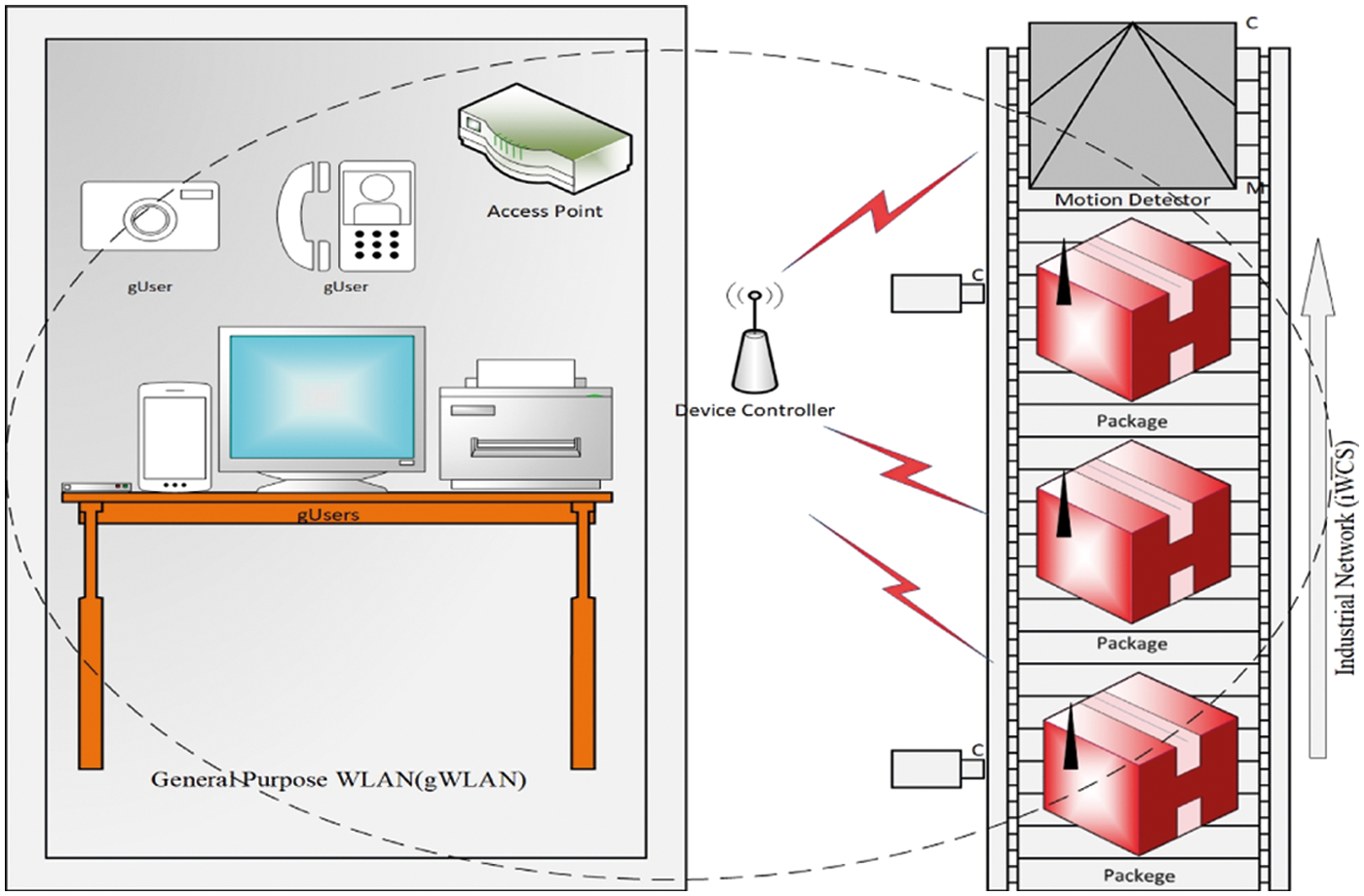
Figure 1: Industrial wireless control and monitoring applications using iWCS collocated with gWLAN
The performance degradation of iWCS can be measured using several techniques, e.g., experimental, simulation-based and analytical. Recently, there have been considerable research efforts put in place to model the performance analysis of wireless networks when they are collocated with one or more different types of wireless networks. This research area tends to increasingly attract attention since more heterogeneous wireless networks continue to be redundantly deployed in a small area with an aim of supporting various types of wireless devices running a variety of applications. In these densely overlapped heterogeneous networks, wireless nodes are forced to contend with others in the same network and simultaneously with nodes of different networks which may run either the same MAC protocol or different ones. The most typical example of overlapped heterogeneous networks is the case where gWLANs based on IEEE 802.11 coexist with wireless personal area networks (WPANs) based on IEEE 802.15.4 and they share the same frequency band in a contention-based manner. Besides the gWLAN and WPAN overlapping some researches addressed the problems yield from the coexistence of Bluetooth and WLAN and Bluetooth and WPAN (Zigbee). However, there is a lack of research on the performance analysis when a iWCS overlaps geographically with the gWLAN, namely, the coexistence of two types of wireless systems running different MAC algorithms to obtain access to the shared wireless channel. In next paragraph at first we briefly explain the operation of gWLAN in DCF (Distributed Coordination Function) and iWCS.
Fig. 2 shows the operation of IEEE 802.11 based gWLAN in DCF mode [6]. All devices initially choose a backoff counter randomly from the minimum contention window and starts counting down after sensing the channel idle for DIFS (DCF InterFrame Spacing) time period. A device makes transmission attempt when its backoff counter reaches zero and all other devices hearing transmission freeze their counters and set network allocation vector (NAV) for the time of transmission. The transmission is successful when no other device's backoff counter reaches zero simultaneously. In this case the sender device receives ACK frame from the destination device otherwise collision happens. In case of collision contention window is increased according to the binary exponential backoff (BEB) algorithm and the station again starts decreasing its counter. The same process is repeated unless the transmission is successful or the number of retries reaches the predefined retry limit in which case the frame is discarded and the upper layers of the protocol stack are notified of the transmission failure.
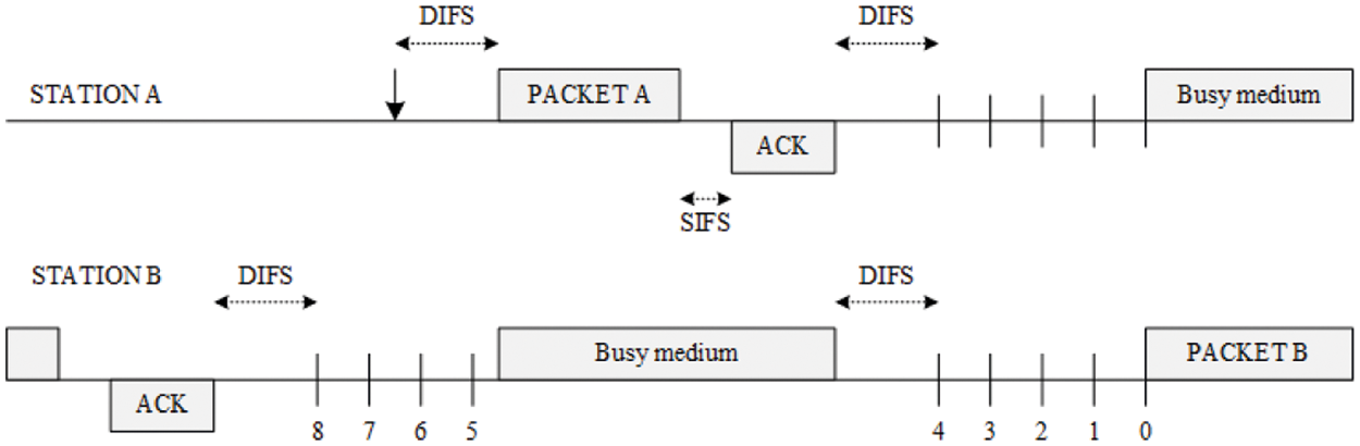
Figure 2: Operation of IEEE 802.11 based gWLAN using DCF
In contrast to gWLAN, transmissions in iWCS happen in round-robin fashion [6]. Fig. 3 shows the operation of iWCS which operates only in infrastructure-based network. Device Coordinator or Device Controller (DC) transmits a beacon frame initially which is received by all the associated devices in the network. All transmissions are in a sequential fashion, i.e., all associated devices are served one by one if they have a frame waiting at the DC thus avoiding collision. DC proceeds to next transmission after an ACK frame is received from the previous transmission. Transmission is not failed due to collision; however, it can be failed due to the channel error. In case of transmission failure iDevice will not receive ACK frame from the DC for the uplink traffic and hence information is re-transmitted until the transmission is successful or the retry limit is reached as shown in Fig. 3. Such failures due to channel error degrade the performance of network. While in this study we consider the MAC operations for gWLAN and iWCS as shown in Figs. 2 and 3, they are not much different than those proposed by various IEEE 802.11 based standards as shown in Fig. 4. The taxonomy in Fig. 4 shows the already established and recently emerged IEEE standards which has suggestions for the enhancements of MAC protocols for WiFi.
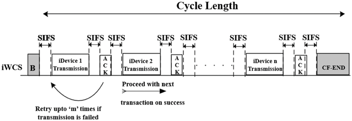
Figure 3: Operation of iWCS with bounded delay
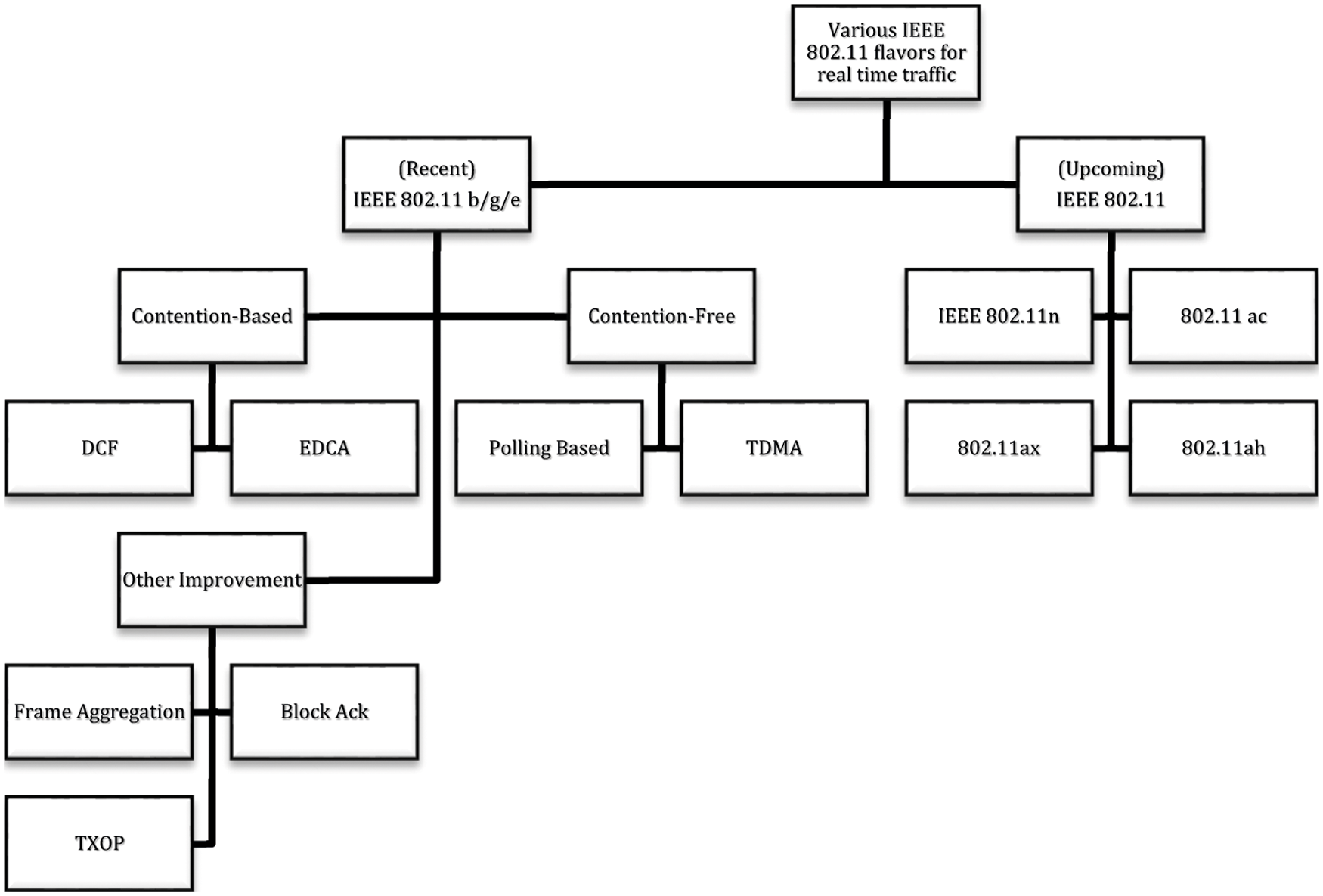
Figure 4: Various established and recently emerged IEEE 802.11-based MAC protocols for general-purpose and real-time traffic
In this paper, we consider the collocation of the time-stringent industrial network (iWCS) based on TDMA MAC with the contention based general purpose wireless network (gWLAN). We evaluate the performance degradation of iWCS due to gWLAN using our proposed analytical model. Furthermore, to enhance the performance of iWCS in the presence of gWLAN we propose an adaptive transmission power control mechanism (ATPC).
The rest of the paper is organized as follows: Section 2 describes the literature review. In Section 3, we formulated the coexistence scenario. The proposed performance model is presented in Section 4 and Section 5 and validation is performed in Section 6. An adaptive transmission power control mechanism is proposed and evaluated in Section 7 and finally Section 8 concludes the paper.
A study conducted by Fotis et al., discussed the dependability of wireless communications for IIoT (Industrial Internet of Things) to provide new solutions [7]. This study also discussed the recent efforts in benchmarking the IIoT protocols and systems and highlighted the challenges that the research community is facing. The IoT devices, however, they considered for their study are based on the low power, low range Bluetooth and IEEE 802.15.4 protocols which unfortunately provide low data rate, too.
Many recent articles focus on the improvement of the WLAN performance in the Industrial setup in terms of reliability and determinism. For example, Karaca et al. in [8] proposed algorithms for fixed and dynamic scheduling duration. The network is divided into groups, where there will be fixed number of users whose transmissions will be scheduled. To improve determinism, in real-time industrial communication, in [9] authors propose a framework that provide seamless link-level redundancy and redundant WLAN equipment assuming that all WLAN devices are dual band and AP supports simultaneous dual band operations as well. [10] proposes a hybrid channel access mechanism along with temporal redundancy techniques to provide deterministic and reliable connectivity for the industrial real-time communication. These previously stated solutions, however, are only suitable when the industrial communication network is the only wireless network operational in the factory shop. The real challenge is when the industrial wireless network is collocated with the another wireless network having different MAC layer mechanism for the channel access. Because when wireless networks of different types are deployed in the same geographical location they interfere each other and therefore degrades each other performance. For example, it was reported in [11] that an IEEE 802.15.4 network suffered approximately 90% throughput drop when it was placed close by IEEE 802.11 networks. In another study, authors demonstrated that the performance of IEEE 802.11 networks dropped as much as 60% when they are placed within the proximity of IEEE 802.15.4 networks, implying that the signal of the former would be overwhelmed by even the weak signal transmission of the latter [12]. In [13] an analytical model was presented by Zhang & Shin to predict the effect of interaction between contention free period (CFP) of ZigBee and Wi-Fi networks on their performance. Their proposed model, however, makes an unrealistic assumption that Wi-Fi stations stay in an unsaturated condition so that they always keep the minimum CW. In [14], Park et al. studied the coexistence of contention based WLAN and WMAN (wireless metropolitan area networks) in which they found that the latter network significantly degrades the performance of the former network. In their study, both the networks are used for the general-purpose communication with no critical delay considerations. They proposed a negative ack (NACK) based signaling mechanism through which WLAN notifies WMAN of its presence. In [15] authors proposed an analytic model for the performance analysis of WLAN when it is in CFP mode and transmission failure occurs only due to the erroneous channel. The research, however, lacks simulation and does not take into account the possibility of transmission failure due to the transmission from a collocated wireless network. Sikdar in [16] presented an analytic model to find delay in PCF based medium access. Their work, however, does not take into account transmission failure either due to channel error or due to the collocated DCF traffic. In [17,18], authors proposed a TDMA (time division multiple access) based mechanism for the real-time communication and proved that their proposed mechanism performs better than the conventional 802.11e EDCA when the high priority traffic competes for the shared channel access with the low-priority traffic. Their work, however, is based on simulations only and an analytic model is not proposed. Furthermore, stations transmitting high priority traffic can sense the channel occupation by the stations transmitting low priority traffic and vice versa. In [19], authors provided an analytical model to evaluate the performance measurement of a wireless network which is collocated with ‘N’ generic number of wireless networks of the same type. Their proposed model is only applicable when all the collocated networks uses the same CSMA/CA based MAC protocol. In [20], authors evaluated the energy efficiency of a wireless network when all the nodes transmit to the same access point using CSMA mechanism. Their proposed mechanism, however, assumes that all the nodes use the same access mechanism for transmission. In [21], Kanjanavapastit et al. presented a modified PCF (Point Coordination Function) which is based on the collision resolution technique. The modified PCF is proposed to reduce the effect of hidden stations in the network. The PCF in this work, however, considers that nodes contend the channel using Polling frames for the uplink transmission which may incur higher transmission delay and are not suitable for the timing stringent tasks in industrial setup. In [22], Guo et al. studied the impact of TDMA (time division multiple access) based Wi-Fi on CSMA based Wi-Fi. when they are collocated in industrial setup. However, they did not take into account the real scenario in which CSMA (Wi-Fi) networks impact the performance of TDMA (Wi-Fi). Their results are also based on the custom made C++ simulator and not the well-known network simulator ns-2 or ns-3. Furthermore, the Wi-Fi standard (IEEE 802.11b) that they have used is obsolete now. In contrast to the above studies our work addresses the real issues that arises from the coexistence iWCS and gWLAN, where the devices in former network transmit with lower transmission power and are susceptible to interference from the transmissions of devices associated with the later network.
In [4], authors studied the suitability of rate adaptation algorithm for the reliable real-time communication in the Wi-Fi based industrial networks. To be more specific, their work focused on assessing the computational complexity of various rate adaptation algorithms based on the experiments. While the obtained results from their experiments are encouraging, their work does not consider the coexistence of wireless industrial networks with other heterogeneous networks.
In [2], author proposed a novel medium access control protocol and provided hardware implementation for Industrial networks. The results they obtained from the experiments are although encouraging, however, the packet error rate due to erroneous channel that they have considered is very low, i.e., 10−9. More specifically the packet error rate due to the heterogeneous wireless network that we considered in this work is higher than the one they have considered.
In [3], authors provided comprehensive survey for the use of IEEE 802.11 MAC enhancements for the real-time industrial networks. The survey concluded that the contention-based MAC protocols are easy to deploy and implement but are not suitable for the wireless industrial networks whereas the contention-free protocols are more suitable for time-stringent industrial applications. The survey also explored the newly introduced enhancements in the MAC e.g., retransmission management and rate adaptation. All the surveyed researches considered a standalone wireless network. In contrast, we considered the collocation of the time-stringent industrial network based on TDMA MAC with the contention based general purpose wireless network.
In this section we present the coexistence scenario of iWCS and gWLAN as shown in Fig. 5. It shows that both networks are physically located closer to each other. More specifically, iWCS is under the influence of gWLAN transmission. Both networks, as stated earlier, are using different rules to access the shared medium. In iWCS, a device coordinator or controller (DC) communicates with its associated devices and in gWLAN the gUsers communicate with the access point (AP). The larger circle around the gWLAN shows that every gUser can sense each other's transmission as long as they remain in this area. The smaller oval shape around the iWCS shows that iDevices and DC have weaker signals that may reach only to each other. In addition, there exists asymmetry between the two networks in terms of transmission powers and carrier sensing while accessing the same shared wireless channel. iDevices transmit without carrier sensing with low transmission power whereas gUsers transmit with higher transmission power having higher carrier sensing threshold since the gUsers are scattered geographically over a wide area and may compete with each other to access the shared medium. On the other hand, the signal strength of the AP and gUsers are strong to may interfere the transmission going on in iWCS. iDevices and DC are non-mobile and pose no serious threat to the communication going on in gWLAN.
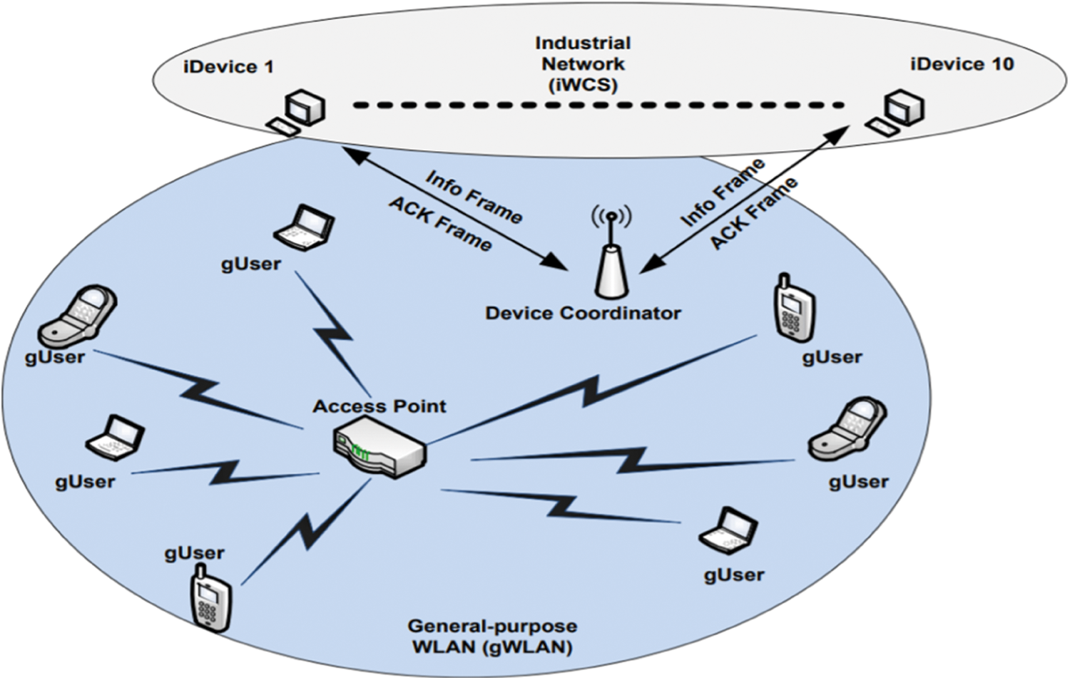
Figure 5: A scenario of collocation of gWLAN and iWCS
Fig. 6 shows the timeline diagram when both iWCS and gWLAN are operating in parallel. Contention free interval in iWCS starts with the transmission of beacon frame from the DC. All the iDevices start sequentially sending receiving frames from the DC after listening to the short beacon frame. gUsers may be oblivious to the short beacon frame due to its low signal strength and therefore may transmit its data assuming the shared channel is idle. This transmission from the fellow gUser when the channel has already been occupied by the iWCS causes the later transmission to be interfered. Resultantly the iDevice has to retransmit that frame causing the indeterministic delay to the real-time communication. Besides the fluctuating delay iWCS also suffers from degraded performance when it is geographically collocated with the gWLAN. To measure the delay incurred by the iWCS due to the interference from the gWLAN, in next section we present an analytic model.
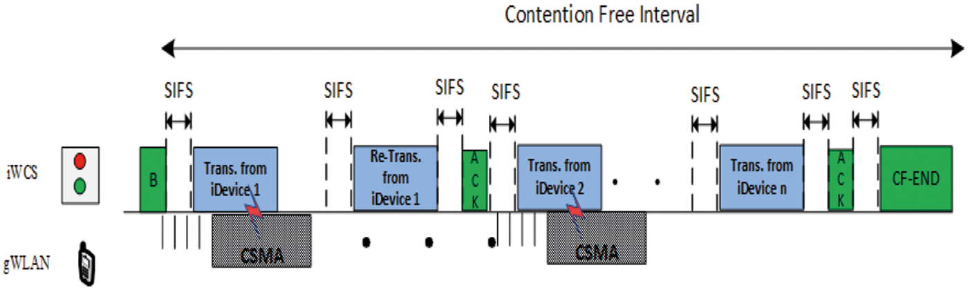
Figure 6: Overlap of iWCS and gWLAN transmissions
4 Performance Model for the iWCS Collocated with gWLAN
This section explains an analytic model to determine the performance of iWCS that shares the same frequency band and is geographically collocated gWLAN on a factory floor. In this work gWLAN having higher transmission power interferes transmissions of the iWCS that transmits without carrier sensing. The rationale behind this assumption is that the gWLAN users are scattered on the factory floor and may therefore need higher transmission power in order for their respective signals to reach to the associated AP.
Fig. 7 shows a Markov chain for network operating in contention-free mode. “Start” and “Finish” represent the start and finish states of a transaction. Similarly, “RS i” represents the ith retry stage of the DC for transmitting a frame to a particular station. There are two cases when transmission of iWCS is failed. They are: (i) when DC has already occupied the channel and the transmission of gWLAN arrives in the middle of CF (Contention-Free) data or ACK frame, thus interfering data or ACK frame (ii) when gWLAN has occupied the channel and a CF transmission arrives which causes the latter transmission being failed.
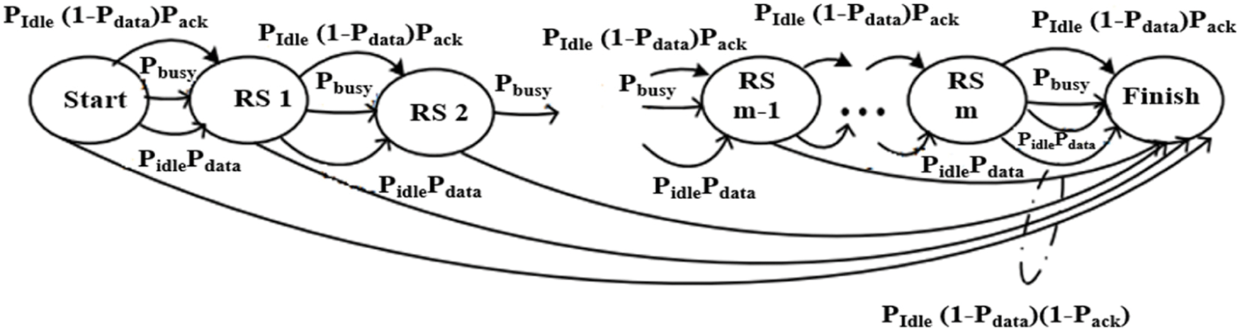
Figure 7: Markov chain for iDevice operating in iWCS in round-robin fashion
With a finite retry limit, a transaction always finishes after m retries. The transitional delays DR, DS and DF represent the delays to reach a retry state from any other state, to reach Finish state from the Start or RS1 ∼ RSm−1, and to reach Finish from RS m, respectively. These transitional delays are given as:
Length of a transaction, represented as T, is determined by calculating the weighted sum of the delays in every possible path from the Start state to the Finish state with the transitional probability as the weight for an associated transition in Fig. 7.
The length of contention free interval of a iWCS having n number of associated iDevices is
here L is the size of data frame and Ec is the bandwidth loss due to the interference from the coexisting gWLAN running in CSMA mode and is given as
5 Calculating Interference Probabilities
In this section, we calculate the interference probabilities of data and ACK frames. Both interference probabilities depend on the number of stations in the collocated gWLAN and the frame sizes. Let nC be the number of stations in the gWLAN, then the transmission probability τ according to [24] is given as
where p is the collision probability when more than one gWLAN stations transmit with probability τ in the same time slot and is given as
Here Vdata and Vack are calculated as TD/σ and TA/σ, respectively, σ = 9us and is the duration of the time slot for the IEEE 802.11a. Substituting
In this section, we validate our analytic model via simulations and discuss the results. For simulations we use ns-2 simulator [25]. The default ns-2 distribution only has IEEE 802.11 DCF module. For iWCS we modified the WLAN Power Management Extension for ns-2 [26].
The values assigned to PHY/MAC parameters of wiresless networks that is assumed to be employed by both iWCS and gWLAN are given in Tab. 1. First of all, Fig. 8 shows that the results obtained from ns-2 simulation [25] closely follow the results obtained from the proposed analytical model for various number of iDevices and hence validate the mathematical model. Furthermore, Fig. 8 shows iWCS throughput in the absence and presence of gWLAN. iWCS throughput is obtained when the number of iWCS devices vary from 5 to 20 for the fixed payload size of 100 bytes. As shown in Fig. 8 iWCS performs better in the absence of gWLAN users i.e., when nC = 0. Furthermore, the lowest iWCS throughput is obtained when there are two gWLAN users are present in the vicinity of iWCS, i.e., when nC = 2.
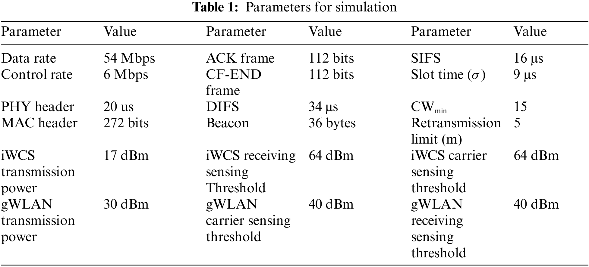
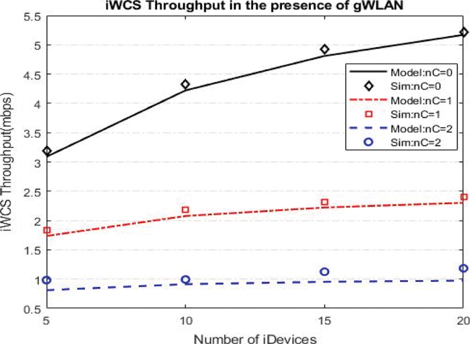
Figure 8: Throughput Comparison of iWCS in the presence and absence of the gWLAN
Fig. 9 shows the packet loss probability with respect to the payload size and number of gUsers present. It can be seen from the figure that the packet loss probability is lowest when the payload size is 50 bytes in the presence of only one gUser. In contrast, packet loss probability reaches highest when the payload size is maximum and the number of gUsers are two. Hence, the packet loss probability reaches high when the vulnerable period is large. Furthermore, iWCS does not suffer any packet loss when there is no gUser in the vicinity, i.e., when nC= 0 and assuming there is no channel error.
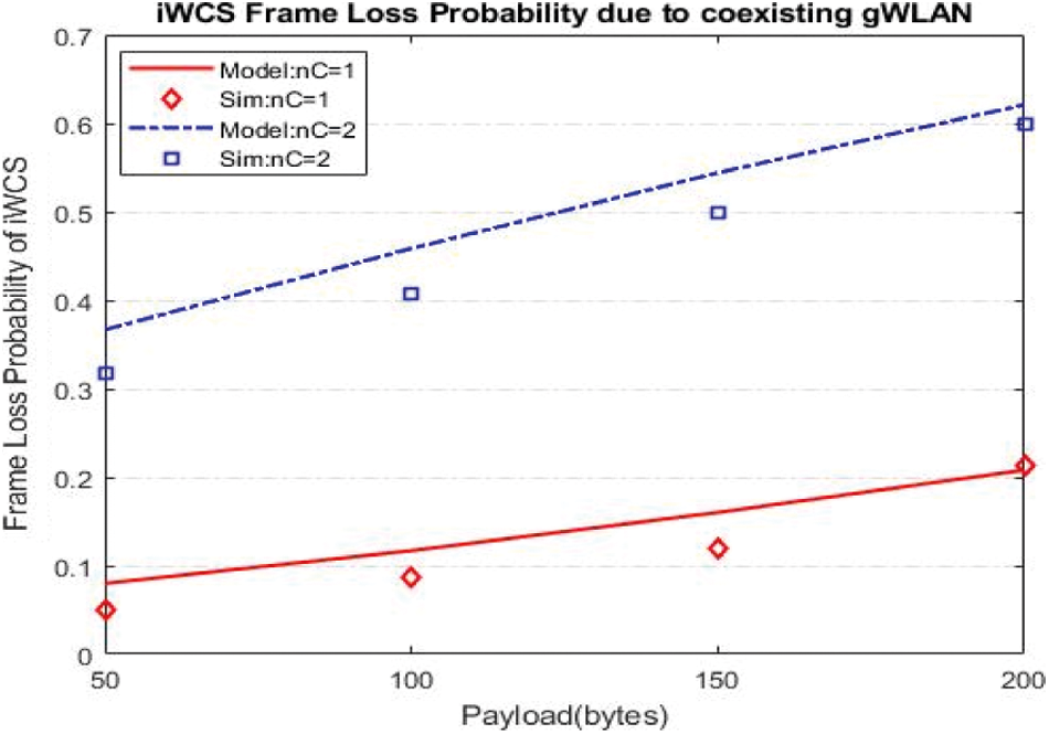
Figure 9: Data frame loss probability of iWCS in coexistence of gWLAN
Fig. 10 shows the transaction length (in milliseconds) against the payload size. Transaction length can be defined as the time when a single packet gets through from the iDevice to the DC. Transaction length is evaluated in the presence of collocated gUsers. It can be seen that transaction takes minimum time when the payload is minimum, i.e., 50 bytes and there is no collocated gUser. In contrast, the transaction time reaches highest when the payload size is 200 bytes and the number of interfering gUsers are two. Hence, Transaction time increases with the increase in interference. The larger the payload size and the number of interfering gUsers the higher will be the transaction time. Fig. 10 also validates the accuracy of the mathematical model.
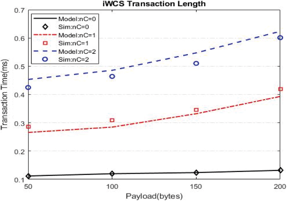
Figure 10: iWCS Transaction length against varying size of payload
Fig. 11 shows the length of cycle (in other words contention free interval) in milliseconds for various payload sizes and the number of interfering gUsers when the number of iDevices is 10. Contention free period (CFP) is the total time spent to serve each associated iDevice, beacon transmission time and the contention-free end (CFE) frame transmission time. From Fig. 11 it is evident that the length of CFP is small when there is no interfering gUser, however, it increases as the size of the payload and the number of interfering gUsers increase. For example, length of CFP is only around 2.7 ms when there are 10 associated iDevices with payload size of 200 bytes and only one interfering gUser, however, the length of CFP reaches almost 3.6 ms when the number of gUsers are increased to two for the same payload size and same number of iDevices. This is almost 33% increase in the total length of the cycle when the number of interfering gUsers increases from one to two.
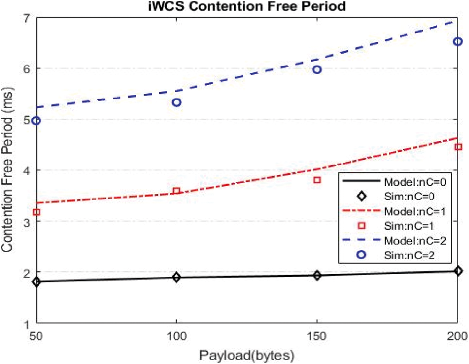
Figure 11: Length of contention free period
Fig. 12 shows relationship between frame loss probability and retry limit. It can be seen that frame loss probability decreases with the increase in the retry limit m for the same payload size. The reason is that interference probability
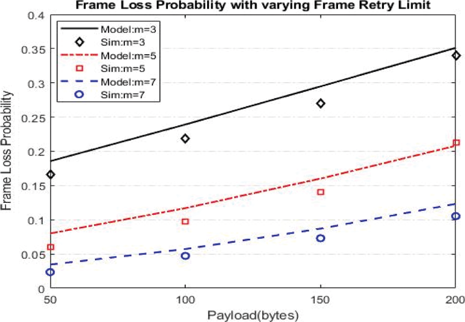
Figure 12: Relationship between frame loss probability and frame retry limit
7 Proposed Adaptive Transmission Power Control (ATPC) Mechanism to Enable the Harmonious Coexistence of iWCS and gWLAN
In this section, we present our proposed solution to enhance the performance of iWCS when it is collocated with gWLAN. The proposed solution is based on the adaptive transmission power control (ATPC). According to ATPC, an iWCS node sending frame at first try will transmit using default transmission power level as shown in Tab. 2 and Fig. 13. If transmission is successful, it will receive ACK, otherwise it will select the next transmission power level available on the next retransmission of the frame. Note that the iWCS node adaptively increments power levels which have already been defined. The default transmission power level is the lowest transmission power, i.e., 10.54 dBm, available. Assume that the transmission of the iWCS node is successful at nth retry using the (n-1)th transmission power level, then it will immediately downgrades its transmission power level. In our proposed technique the total number of transmission power levels are equal to the maximum number of retries, i.e., m which is 10 as shown in Fig. 13.
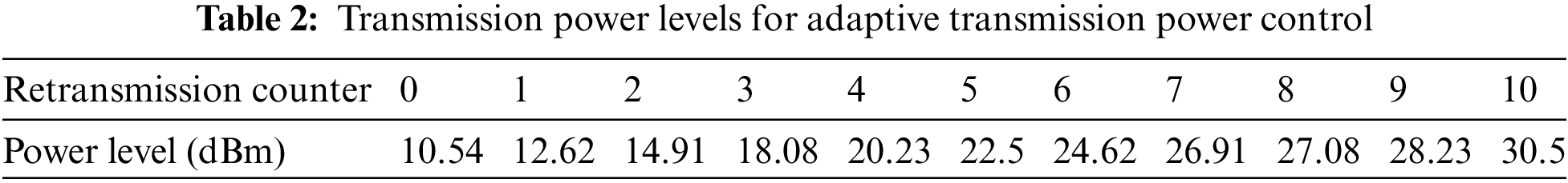
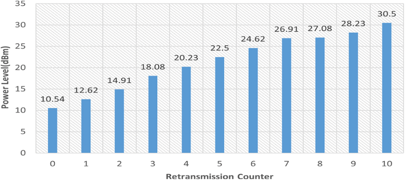
Figure 13: Gradual increase of transmission power levels with retransmissions
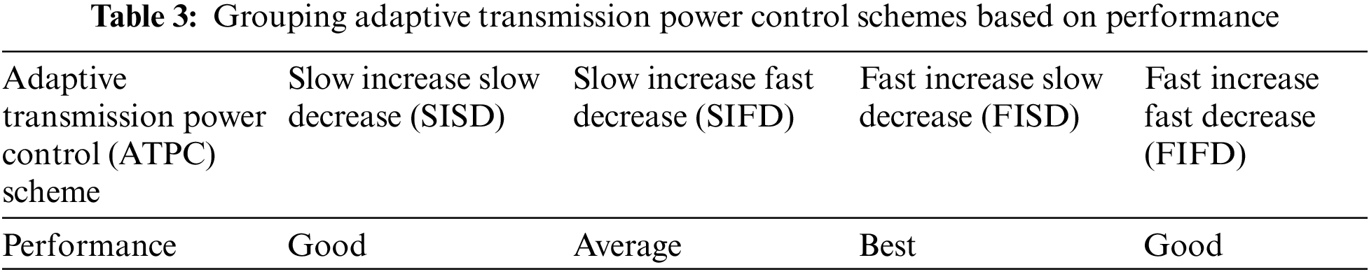
The adaptive increase in transmission power serves at least one purpose: (i) iWCS transmission is heard by the gWLAN user who will freeze its backoff before transmission, giving a safe transmission opportunity to the former. (ii) Both transmissions overlap in time but physical capture occurs at the respective receivers instead of collision, i.e., the receiving power of the receiving signal at DC for iDevice is usually higher than that coming from the gWLAN user, thus making physical capture successful. Similarly, the opposite happens at the AP, where gWLAN signal overpowers iWCS. Simulations shows that ATPC does not have significant adverse effect on the performance of gWLAN but it can significantly improve the performance of iWCS. We define four subtypes of ATPC, (i) Slow Increase Slow Decrease (SISD) (ii) Slow Increase Fast Decrease (SIFD) (iii) Fast Increase Slow Decrease (FISD) (iv) Fast Increase Fast Decrease (FIFD). Transmitter will adapt the transmission power upon transmission success or failure according to one of the four mentioned subtypes of ATPC. For example, the iDevice increases its transmission power slowly (additively) for the next transmission attempt when its current transmission is failed. Upon each transmission failure the transmission power is increased till the transmission retry is reached. iDevice may also increase its transmission power fast (exponentially) upon current transmission failure for the next transmission attempt. This slow or fast increase in transmission power level is decided upon which ATPC subtype is used. Similarly, iDevice reduces its transmission power level slowly (additively) or quickly (exponentially) upon each successful transmission till basic (or default) transmission power is reached. Again, whether to reduce transmission power level slowly or quickly depends on the subtype of the ATPC that is used.
We have defined 10 transmission power levels and have been arranged in ascending order as shown in Tab. 2. Now let's discuss the operation and performance of each subtype. (i) Increase in Transmission Power Level: In SISD, transmission power level is increased slowly when transmission is failed and decreased slowly when transmission becomes successful. Since there is no contention in iWCS and transmission failure due collision is not possible, therefore the only reason of transmission failure is interference due to transmission from the geographically collocated gWLAN nodes. Hence, ATPC is invoked whenever iDevice does not receive ACK in response to its transmission, i.e., transmission power level is increased additively in SISD. This slow (additive) increase in transmission power level is also used in SIFD. (ii) Decrease in Transmission Power Level: The transmission power decrementing function is invoked at the time of successful transmission. Transmission power level is decremented upon successful transmission, i.e., when the transmitting iDevice receives ACK frame in response to the transmission. In SISD, this transmission power level is decremented slowly, i.e., additively till the default transmission power is reached. For example, when the current transmission is successful and the current transmission power level is 5, then it will be decremented to 4. In FIFD, on the other hand, transmission power level decrements fast or in other words, exponentially. For instance, for the 3rd transmission attempt iDevice used the 8th transmission power level and successfully received ACK frame. Now for the next transmission attempt the transmission power level will be reduced exponentially resulting in the 4th transmission power level. Below we discuss the simulation results that have been obtained using the four subtypes of our proposed ATPC scheme. At first we compare the results obtained from using the four proposed approaches when the number of gUsers are only one and compare it with the baseline approach in which transmission power remains default regardless of the success or failure of the transmission. Fig. 14a shows that all the four proposed approaches give better throughput compared to the baseline approach. Furthermore, it can be seen that out of the four proposed approaches, FISD outperforms the remaining three adaptive TPC approaches, whereas the throughput obtained from SIFD is just closer to the baseline approach. In FISD, the iDevice increases the transmission power level aggressively but uses a very laid-back approach in reducing the transmission power level when the transmission is successful. It means iDevice retains higher transmission power for comparatively longer duration. In contrast, SIFD uses a laid-back approach in increasing its transmission power level when its transmission is failed and reduces its transmission power level more abruptly upon successful transmission. The remaining two approaches, i.e., SISD and FIFD give almost average performance. It takes several transmission failures for SISD to set its transmission power to higher level and then slowly reduces its transmission power level on the receipt of ACK control frame from the Point Coordinator. Similarly, using FIFD iDevice increases its transmission power aggressively when it does not receive ACK frame within the defined ACK timeout duration making its transmission successful on the next retransmission attempt. However, using FIFD iDevice does not retain a higher transmission power level for longer time and reduces its transmission power level abruptly upon successful transmission.
Simulation results for the performance of iWCS when it is collocated with two users of gWLAN is shown in Fig. 14b. The performance curve shown in Fig. 14b follows almost the same trend shown in Fig. 14a. The overall performance of the iWCS when it is collocated with two users is lower than when it is collocated with one gWLAN user regardless of the ATPC scheme being used. However, like the case with one gWLAN user, here too the four proposed ATPC schemes perform better than the baseline mechanism where none of the ATPC scheme is operating. It is also shown in Fig. 14b that FISD gives the best performance, whereas SISD and FISD gives above average (Good) performance and SIFD gives the lowest (Average) throughput. After observing the results obtained from the extensive simulations, we place the proposed scheme in one of the following categories: Best, Good and Average, as shown in Tab. 3.
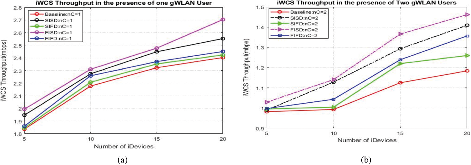
Figure 14: Comparison between four different adaptive transmission power schemes in the presence of (a) one coexisting gWLAN user and (b) two coexisting gWLAN users
7.1. Impact of ATPC Employed in iWCS on the Performance of gWLAN
In previous Section, it was shown that all the ATPC schemes were showing promising results. However, it is important to analyses the impact of ATPC on the performance of the collocated gWLAN as well. In this Section, we show how ATPC impacts the performance of gWLAN. Please note that all the bars show the throughputs of the gWLAN only but maps to the different scenarios. Let us first discuss the throughput obtained by one gWLAN user when it is collocated with iWCS as shown in Fig. 15. gWLAN throughput is obtained in both cases when iWCS is not employing any ATPC (Baseline) and when it is employing ATPC (FISD, SISD, FIFD or SIFD). It can be seen that the Baseline scenario achieves highest throughput, i.e., 4.15Mbps) while it achieves approximately 4.10 Mbps throughput when the collocated iWCS is employing the ATPC scheme. This drop in gWLAN throughput is, although, obvious but is not very significant. The reason behind this not so significant performance drop is that the gWLAN user occasionally waits for the iDevice transmission when the latter is transmitting with higher transmission power which exceeds the gWLAN carrier sense threshold forcing it to freeze its backoff. This freezing of the gWLAN backoff also depends on the relative positions of the two users, e.g., gWLAN and iDevice. In our simulation if the gWLAN user is located within 50meters of the iDevice and the latter is transmitting using ATPC with higher transmission power, the gWLAN can listen iDevice transmission. However, not all iDevices fall in the carrier sense range of the gWLAN user. Furthermore, when iDevice and gWLAN transmit simultaneously, the PHY captures of their respective transmission happen at the respective receivers, giving a higher successful transmission opportunity to the iWCS without impacting the transmission of the gWLAN.
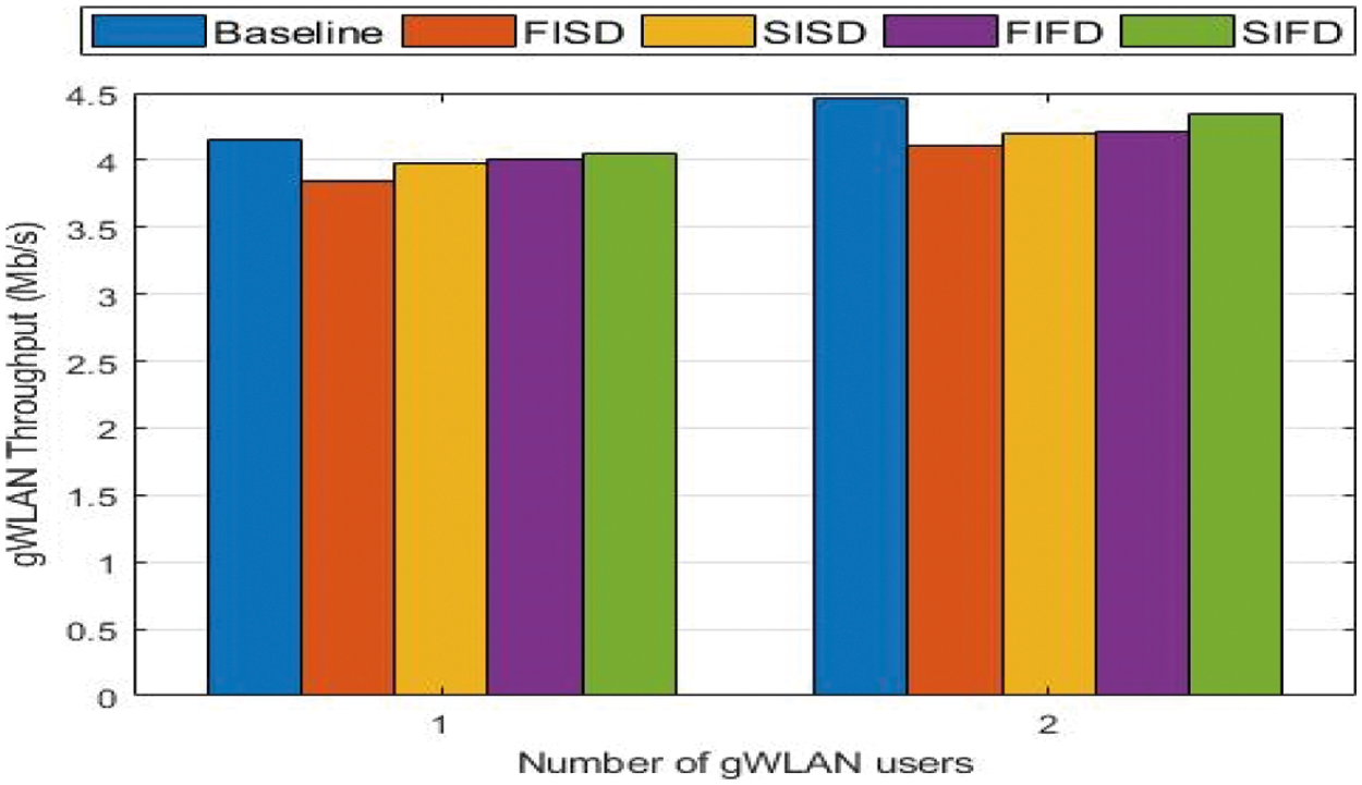
Figure 15: Impact of ATPC schemes employed in iWCS on the Performance of gWLAN
From Fig. 15, it can be seen that gWLAN throughput is effected differently with different ATPC scheme. For example, it is less effected when iWCS is using SIFD scheme. The reason is that using SIFD, iWCS retains higher transmission power level for small duration and would quickly downgrades its transmission power level immediately after successfully transmission. In contrast, gWLAN performance is not much different when iWCS is using either SISD or FIFD. Finally, gWLAN performance when iWCS is using FISD is more impacted as compared to the situation when iWCS employs one of the remaining three ATPC schemes (such as SISD, FIFD, and SIFD). The reason is that when iWCS transmits using FISD, it quickly acquires higher transmission power level and will retain it for more time. For as long as iDevice transmits with higher transmission power, it will win the PHY capture in case its transmission is overlapped with the gWLAN particularly when the distance between the two heterogeneous devices is less than 50.
Now that it is obvious from the previous simulation results that FISD outperforms all other adaptive transmission schemes, next we find out the transaction delay and the cycle length, i.e., CFP. The evaluation of these two parameters are important for the delay critical applications of the industrial network. For both types of delay evaluations, we used only FISD as shown in Fig. 16. Firstly, from Fig. 16a, it is evident that the transaction time is reduced in both cases, i.e., when the number of coexisting gWLANs users are one and two, respectively. Transaction time of iWCS in the presence of one and two gWLAN users is reduced from 0.30 ms and 0.4640 ms to 0.25 ms and 0.41 ms, respectively. Secondly, Fig. 16b shows complete contention free interval in which all the 10 iDevices in iWCS are served, in the presence of one and two gWLAN users. It is found that the cycle length duration is reduced from 3.7 ms and 5.96 ms to 3.1 ms and 5.1 ms, respectively, in the presence of one and two interfering gWLAN users. Consequently, the overall reduction in delay is approximately 13∼15%.
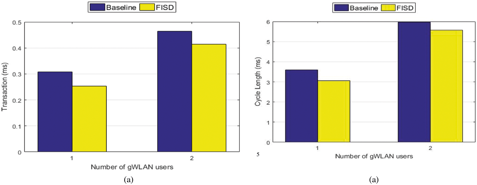
Figure 16: (a) iWCS transaction delay (b) iWCS cycle length in the presence of gWLAN Users
In this paper, we proposed an analytic model for the performance analysis of industrial wireless communication system when it shares the wireless medium with the general purpose WLAN (gWLAN) while the later is frequently interfering the former's transmissions due to its higher transmission power and carrier sense threshold. We found that the performance of the iWCS is severely degraded when collocated with the gWLAN. Our model accurately predicts the performance degradation of iWCS by the collocated gWLAN. The presented model is validated via results obtained from ns-2 simulations. Then, we proposed an adaptive transmission power control (ATPC) mechanism for iWCS to overcome the interference caused by the collocated gWLAN. Results from extensive simulations show that our proposed ATPC scheme outperforms the baseline approach in terms of throughput and delay. In our future work, we will devise an analytical model for the coexistence of wifi-based industrial networks with low-power wireless technologies such as Bluetooth and Zigbee to investigate the performance degradation they cause to each other.
Funding Statement: This research was supported by the Basic Science Research Program through the National Research Foundation of Korea (NRF) funded by the Ministry of Education (No. 2018R1D1A1B07049758).
Conflicts of Interest: The authors declare that they have no conflict of interest to report regarding the present study.
1. R. S. Mogensen, I. Rodriguez, C. Schou, S. Mortensen and M. S. Sørensen, “Evaluation of the impact of wireless communication in production via factory digital twins,”Manufacturing Letters, vol. 28, pp. 1–5, 2021. [Google Scholar]
2. K. Tittelbach-Helmrich, N. Odhah and Z. Stamenković, “A novel medium access control protocol for real-time wireless communications in industrial automation,” International Journal of Communications Network and System Sciences, vol. 10, no. 11, p. 282, 2017. [Google Scholar]
3. Y. Cheng, D. Yang, H. Zhou and H. Wang, “Adopting IEEE 802.11 MAC for industrial delay-sensitive wireless control and monitoring applications: A survey,” Computer Networks, vol. 157, pp. 41–67, 2019. [Google Scholar]
4. T. Fedullo, F. Tramarin and S. Vitturi, “The impact of rate adaptation algorithms on Wi-fi-based factory automation systems,” Sensors, vol. 20, no. 18, p. 5195, 2020. [Google Scholar]
5. D. K. Lam, “A fast and safe industrial WLAN communication protocol for factory automation control systems,” Transactions of the Institute of Systems Control and Information Engineers, vol. 29, no. 1, pp. 29–39, 2016. [Google Scholar]
6. “ISO/IEC/IEEE - International Standard - Information technology--Telecommunications and information exchange between systems--Local and metropolitan area networks--Specific requirements--Part 11: Wireless LAN medium access control (MAC) and physical layer,” ISO/IEC/IEEE 8802-11:2018(E). pp. 1–3538, 2018. https://standards.ieee.org/project/802_11bb.html. [Google Scholar]
7. F. Foukalas, P. Pop, F. Theoleyre, C. A. Boano and C. Buratti, “Dependable wireless industrial iot networks: Recent advances and open challenges,” in IEEE European Test Symposium, Baden-Baden, Germany, pp. 1–10, 2019. [Google Scholar]
8. M. Karaca, S. Bastani, B. E. Priyanto, M. Safavi and B. Landfeldt, “Resource management for OFDMA based next generation 802.11 WLANs,” in 9th IFIP Wireless and Mobile Networking Conf., Colmar, France, pp. 57–64, 2016. [Google Scholar]
9. G. Cena, S. Scanzio and A. Valenzano, “Seamless link-level redundancy to improve reliability of industrial Wi-fi networks,” IEEE Transactions on Industrial Informatics, vol. 12, no. 2, pp. 608–620, 2016. [Google Scholar]
10. A. Aijaz, “High-performance industrial wireless: Achieving reliable and deterministic connectivity over IEEE 802.11 WLANs,” IEEE Open Journal of the Industrial Electronics Society, vol. 1, pp. 28–37, 2020. [Google Scholar]
11. A. Sikora and V. F. Groza, “Coexistence of IEEE 802. 15.4 with other systems in the 2.4 GHz-ISM-band,” in 2005 IEEE Instrumentationand Measurement Technology Conf. Proc., Ottawa, ON, Canada, vol. 3, pp. 1786–1791, 2005. [Google Scholar]
12. S. Pollin, I. Tan, B. Hodge, C. Chun and A. Bahai, “Harmful coexistence between 802.15. 4 and 802.11: A measurement-based study,” in Proc. 3rd Int. Conf. on Cognitive Radio Oriented Wireless Networks and Communications, Singapore, pp. 1–6, 2008. [Google Scholar]
13. X. Zhang and K. G. Shin, “Enabling coexistence of heterogeneous wireless systems: Case for ZigBee and WiFi,” in Proc. of the 12th ACM Int. Symposium on Mobile Ad Hoc Networking and Computing, Paris, France, pp. 1–11, 2011. [Google Scholar]
14. E. -C. Park and M. Rim, “Fair coexistence MAC protocol for contention-based heterogeneous networks,” The Computer Journal, vol. 54, no. 8, pp. 1382–1397, pp. 1-11, 2011. [Google Scholar]
15. M. A. R. Siddique and J. Kamruzzaman, “Performance analysis of PCF based WLANs with imperfect channel and failure retries,” in 2010 IEEE Global Telecommunications Conference GLOBECOM, Miami, Florida, USA, pp. 1–6, 2010. [Google Scholar]
16. B. Sikdar, “An analytic model for the delay in IEEE 802.11 PCF MAC-based wireless networks,” IEEE Transactions on Wireless Communications, vol. 6, no. 4, pp. 1542–1550, 2007. [Google Scholar]
17. R. Costa, P. Portugal, F. Vasques and R. Moraes, “A TDMA-based mechanism for real-time communication in IEEE 802.11 e networks,” in 15th Int. Conf. on Emerging Technologies and Factory Automation, Bilbao, Spain, pp. 1–9, 2010. [Google Scholar]
18. R. Moraes, F. Vasques, P. Portugal and P. F. Souto, “A forcing collision resolution approach able to prioritize traffic in CSMA-based networks,” Computer Communications, vol. 33, no. 1, pp. 54–64, 2010. [Google Scholar]
19. B. Khan and J. -S. Ahn, “Modeling the effect of interferences among N collocated heterogeneous wireless networks,” in 2014 12th Int. Symp. on Modeling and Optimization in Mobile, Ad Hoc, and Wireless Networks, Hammamet, Tunisia, pp. 167–172, 2014. [Google Scholar]
20. B. Khan, R. A. Rehman and B. S. Kim, “A joint strategy for fair and efficient energy usage in WLANs in the presence of capture effect,” Electronics, vol. 8, no. 4, pp. 386, 2019. [Google Scholar]
21. A. Kanjanavapastit and B. Landfeldt, “A performance investigation of the modified PCF under hidden station problem,” in 2004 Int. Conf. on Communications, Circuits and Systems (IEEE Cat. No.04EX914), Chengdu, China, vol. 1, pp. 428–432, 2004. [Google Scholar]
22. X. Guo, S. Wang, H. Zhou, J. Xu, Y. Ling et al., “Performance evaluation of the networks with Wi-fi based TDMA coexisting with CSMA/CA,” Wireless Personal Communications, vol. 114, no. 2, pp. 1763–1783, 2020. [Google Scholar]
23. E. Lopez-Aguilera, J. Casademont and J. Cotrina, “IEEE 802.11 g performance in presence of beacon control frames,” in 2004 IEEE 15th Int. Symp. on Personal, Indoor and Mobile Radio Communications (IEEE Cat. No.04TH8754), Barcelona, Spain, vol. 1, pp. 318–322, 2004. [Google Scholar]
24. G. Bianchi, “Performance analysis of the IEEE 802.11 distributed coordination function,” IEEE Journal on Selected Areas in Communications, vol. 18, no. 3, pp. 535–547, 2000. [Google Scholar]
25. M. H. Rehmani and Y. Saleem, “Network simulator NS-2,” in Encyclopedia of Information Science and Technology, Third Edition, Hershey, Pennsylvania, USA, IGI Global, pp. 6249–6258, 2015. https://www.igi-global.com/chapter/network-simulator-ns-2/113081. [Google Scholar]
26. M. Takyuna, M. Yoshinori and F. Makoto, “Wireless Lan (IEEE 802.11) power management extension,” 2019. http://nspme.sourceforge.net/index.html. [Google Scholar]
 | This work is licensed under a Creative Commons Attribution 4.0 International License, which permits unrestricted use, distribution, and reproduction in any medium, provided the original work is properly cited. |