DOI:10.32604/cmc.2022.025657
| Computers, Materials & Continua DOI:10.32604/cmc.2022.025657 | |
| Article |
A Compact Quad-Band Sickle-Shaped Monopole Antenna for GSM 900/WiMax/WLAN Applications
1Department of Electronics and Communication Engineering, National Institute of Technology, Durgapur, 713213, West Bengal, India
2Department of Electronics and Communication Engineering, University of Engineering and Management, New Town, Kolkata, 700156, West Bengal, India
*Corresponding Author: Sujit Goswami. Email: sujitg.aec@gmail.com
Received: 01 December 2021; Accepted: 16 March 2022
Abstract: In this paper a novel, compact, microstrip-fed, quad-band monopole antenna is presented for the application of Global System for Mobile communication (GSM 900), Worldwide Interoperability for Microwave Access (WiMAX) and Wireless Local Area Network (WLAN). The proposed antenna comprises of a sickle-shaped structure with four circular arc strips, and a modified rectangular ground plane. The four strips of the antenna are independently responsible for the four different resonant frequencies of the operating bands and can be tuned separately to control the radiation performance. The proposed quad-band antenna is designed to resonate at 940 MHz for GSM 900, 2.5 and 3.5 GHz for WiMAX and 5.85 GHz for WLAN applications. At the four intended operating bands, the antenna exhibits impedance bandwidth of 60 MHz (905–965 MHz), 80 MHz (2.45–2.53 GHz), 110 MHz (3.48–3.59 GHz) and 2.39 GHz (4.82–7.21 GHz), respectively. At the resonance frequency of the four bands, the gain of the proposed antenna is obtained as 4.2, 2.5, 1.7 and 1.9 dBi, respectively. A prototype of the designed antenna is fabricated and a good agreement between simulated and measured results is observed. Furthermore, the proposed antenna shows good radiation characteristics and gains at all the four operating bands.
Keywords: Antenna gain; GSM 900; IEEE 802.11a; monopole strips; quad-band; sickle-shaped; WiMAX; WLAN
Due to low profile, conformability to planar, and non-planar surfaces, simple and inexpensive manufacture using modern printed-circuit technology, microstrip antennas are widely used in the present communication systems. A hexa-band quad-circular-polarization with inverted S-shaped slotted patch antenna for the fifth generation (5G) communication, Global Positioning System (GPS), WLAN, Long Term Evolution (LTE), and Radio Navigation applications was reported in [1]. A miniaturized tri-band printed monopole antenna with circular polarization is presented in [2]. The novel half-cutting technique has been implemented on the circularly polarized (CP) dual band antenna to enhance the axial ratio bandwidth for wireless communication in [3]. In [4], a multiband circularly polarized microstrip patch antenna with Minkowski fractal slot for wireless communications is designed. The performance evaluation and design of 5G communication-based millimeter wave antenna is presented in [5]. Radio frequency energy harvesting has attracted considerable interest as a technique of enabling self-powered wireless networks as described in [6] and [7]. In [6], a multiband microstrip patch antenna is designed with three slits and nature inspired optimization method. A compact, multiband, and dual side printed microstrip patch antenna with its performance for RF energy harvesting applications is introduced in [7].
For present wireless communication, design of multiband antenna has got an increased attention to the antenna researchers [8–15]. A compact multi-band antenna supporting multiple radio frequency (RF) bands is required for the portable devices to augment the advanced communication technologies related to different telecommunication standards such as GSM, Universal Mobile Telecommunication System (UMTS), LTE, 5G, and several wireless applications like WLAN, WiMAX. In this regard, several dual, triple or multi-band antennas have been reported. In [8], a co-planar waveguide fed broadband-multiband planar antenna is reported for WiMAX 3.5/5.5 GHz and WLAN 2.4/5.2/5.8 GHz bands. In [9], the coplanar waveguide (CPW) and microstrip line feed spiral-shaped ultra-wide band (UWB) antennas are proposed to work in the applications of digital cellular system (DCS), personal communication service (PCS), bluetooth and WLAN. In [10], a reconfigurable multiband rhombic-shaped patch antenna to operate up to 20 GHz is designed for wireless smart applications. Different multiband patch antennas using various shape and techniques, such as, an inverted upright chair type patch with defected ground structure (DGS) [11], Y-shaped patch [12] and F-shaped slotted patch antenna [13] are found for such applications. Also, multiband monopole antenna with symmetric folded slots [14], and L and U-shaped slots [15] are proposed for UMTS, WiMAX and WLAN. In [16], a modified CPW-fed monopole antenna using small ground plane is reported for multiband WLAN applications. A novel G-shaped slotted dual-band antenna in [17] and a compact wide-slotted tri-band antenna in [18] are also reported for WLAN/WiMAX applications.
However, printed monopole antennas are crucial owing to their unique and specific beneficial characteristics like simple planar structure, smaller size, low profile with plausibly good performance [19–23]. Various theoretical investigations based on different shapes of the monopole antennas like, P-shaped [24], Rhombic-shaped [25], Hook-shaped [26], G-shaped [27], double S-shaped [28], double T-shaped [29], L-shaped [30] and F-shaped [31] have been performed to achieve multiband characteristics. The major issues to realize multiband characteristics are the increased design complexity and size. For reference, triple-band characteristics are obtained with the combinations of two antenna types such as rectangular and circular in [32], ceramic chip and printed radiating elements in [33] and, ear-shaped and circular-arc strips in [34]. In [35,36], a claw-shaped triple-band antenna with three arcs is also proposed in this regard. Another novel printed monopole antenna is proposed for dual-band WLAN applications in [37].
In this paper, a novel, compact, microstrip fed quad-band sickle-shaped monopole antenna with the symmetrically modified ground plane is proposed for GSM, WLAN and WiMAX applications. The proposed sickle-shaped antenna structure comprising four simple monopole arcs provides quad-band characteristics with the independent tuning of the respective band by controlling the dimension of the individual arc. Hence, as compared to the monopole antennas reported in [26–29], the proposed antenna facilitates easier tuning of the respective operating frequency bands of GSM 900 (940 MHz), WiMAX (2.5/3.5 GHz) and WLAN (5.5 GHz).
2 Quad-band Antenna Design and Configuration
The geometrical configuration of the proposed microstrip fed modified sickle-shaped monopole antenna along with the appropriate co-ordinate system is depicted in Fig. 1. The antenna is designed on FR4 substrate with thickness (h) of 1.6 mm, relative permittivity (εr) of 4.4 and dielectric loss tangent (tanδ) of 0.02. The proposed antenna, based on four curved-shaped monopole strips (strips 1 to 4), each resembling the shape of a sickle acts as radiating patches of four independent frequency bands. The sickle-shaped arcs greatly reduce the overall volume of the antenna thereby making it a compact one. To feed the antenna, a microstrip line is introduced on the same side of the substrate containing the radiating patches as shown in Fig. 1a while on the other side of the substrate; the ground plane is modified as in Fig. 1b. The width of the microstrip feed line (Wf) is adjusted to achieve 50 Ω impedance matching and the antenna is excited centrally from its bottom edge. The whole antenna structure is printed on the substrate surface with dimension of 38 mm × 30 mm while the dimension of the modified ground plane is 13 mm × 30 mm.

Figure 1: Analytical dimensions of the proposed modified sickle-shaped monopole antenna
With the aim of designing a quad-band antenna with independent tuning of the respective operating centre frequency, four sickle shaped strips–Strip-1, strip-2, strip-3 and strip-4 are introduced. Corresponding to the four desired frequency bands, the lengths of the strips are calculated for radiating at their respective resonating frequencies of 940 MHz, 2.5 GHz, 3.5 GHz and 5.85 GHz respectively. The design equations to obtain the lengths of the four radiating strips are given as follows:
In Eqs. (1)–(4); R1, R2, R3 and R4 represent the radii of the arc corresponding to strip 1 to 4 respectively; θ1, θ2, θ3 and θ4 are angular sizes of the respective arc strips; Lf and Wf are the length and width of the microstrip feed line; Lg is the length of the ground plane.
The strip lengths are selected close to a quarter of the guided wavelength (λg) of the designed resonating frequencies and the corresponding λg is given by [38]
where εre is the effective permittivity. The widths of the modified sickle-shaped arcs are chosen such that better impedance matching is achieved. For the chosen FR4 substrate, with εr = 4.4, h = 1.6 mm and
Wf = 3 mm, the expression for effective permittivity is obtained as
With substitution of the optimized values of different parameters as depicted in Tab. 1, εre is calculated and it is obtained as 3.32.
The lengths and widths of the radiating strips are optimized for better performance of the antenna specifically in terms of return loss and gain characteristics. Simulation studies are carried out using commercial full-wave EM simulation software, namely Ansys make HFSS v18.0. The parametric studies corresponding to the different length of the strips are shown in Figs. 2a–2d. When one strip length is changed the others are kept at their respective optimized values. From Fig. 2a it is revealed that upon changing the arc length of strip-1 from 67.6 to 69.6 mm, the resonating frequency corresponding to GSM 900 band slightly varies on either side of its optimized frequency. However, the impedance bandwidth and return loss characteristics of the antenna almost remain unchanged. Similarly, upon changing the arc length of strip-2 from 18.1 to 19.3 mm, a slight variation in the resonating frequency is observed in the 2.4/2.5 GHz WiMAX band [Fig. 2b]. Also, variation in arc length of strip-3 from 12.1 to 13.5 mm, a slight change in the resonating frequency is visible from Fig. 2c. Finally, the variation of arc length of strip-4 from 11.6 mm to 13.2 mm, slight changes in impedance bandwidth and resonating frequency is observed in the fourth band [Fig. 2d]. Similarly, the widths of the four strips are also varied and the corresponding changes in the S11 characteristics are shown in Fig. 3a. From the depicted figures, it can be observed that there is a small variation in resonating frequency and impedance bandwidth; however, the overall return loss characteristics are not much altered. It is to be noted that, the resonating frequency of the antenna is inversely related to the antenna dimension. Thus, from Figs. 2 and 3, it can be seen that, with same change in the length and width of the radiating strips, compared to the lower resonance frequencies, the more impact is observed for the highest resonance frequency. Thus, from the parametric studies corresponding to length of the strips, the optimized strip lengths for which better return loss and gain characteristics are obtained in the desired GSM 900/WiMAX/WLAN operating bands are given as l1 ≡ 68.6 mm, l2 ≡ 18.7 mm, l3 ≡ 12.8 mm and l4 ≡ 11.6 mm respectively. Similarly, the optimized strip widths are obtained as d1 = 2 mm, d2 = 1.1 mm, d3 = 1.2 mm and d4 = 1.5 mm respectively. Fig. 3b depicts the return loss characteristics of the designed antenna with the optimized lengths and widths of the different strips. From the parametric studies it is quite evident that a particular operating band of the proposed antenna is primarily affected with changes in its corresponding strip length while the change in the characteristics of that band is negligible with changes in other strips. This shows that by properly tuning a strip length, the corresponding frequency band can be adjusted.

Figure 2: Parametric study of the proposed antenna by variation of length of (a) strip-1, (b) strip-2, (c) strip-3 and (d) strip-4 respectively

Figure 3: (a) Parametric study of the proposed antenna by variation of widths of strips 1–4 and (b) Plot of simulated return loss of the antenna with optimized values of the strips dimensions
From the optimized S11characteristics [Fig. 3b], it is seen that the proposed antenna exhibits quad-band operation with resonating frequencies of 940 MHz, 2.5 , 3.5 and 5.85 GHz, corresponding to the four operating bands of GSM 900, WiMAX 2.5/3.5 and WLAN U-NII (Unlicensed National Information Infrastructure) respectively. In the four operating bands, the proposed antenna offers 10 dB impedance bandwidth of 60 , 80 , 110 MHz and 2.39 GHz covering the frequency ranges of (905–965) MHz, (2.45–2.53) GHz, (3.48–3.59) GHz and (4.82–7.21) GHz, respectively. Further, the minimum values of S11 at the four resonating frequencies of the operating bands are obtained as −22 dB at 940 MHz, −19 dB at 2.5 GHz, −28 dB at 3.5 GHz and −44 dB at 5.85 GHz. These results show that the proposed antenna provides good impedance matching over the entire operating frequency bands and finds its suitability for the intended multiband communication systems.
4 Analysis of Surface Current Distribution
The electric field and the surface current distributions of the proposed antenna at the center frequency of the four operating bands are depicted in Figs. 4a–4d and 5a–5d respectively. From the figures, it is clearly visible that compared to the other region of the antenna, both electric field and surface current corresponding to a particular frequency is mostly confined to a particular strip region. This indicates that the strip under which the field as well as the surface current is confined is responsible for the radiation of the respective operating bands.
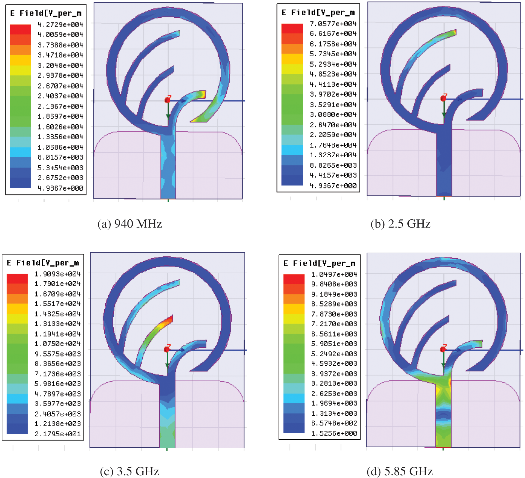
Figure 4: Electric field distribution of the proposed antenna at different frequency bands
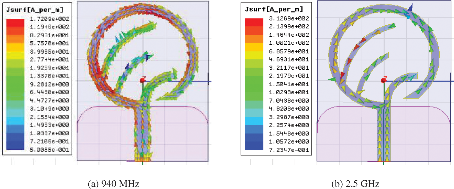
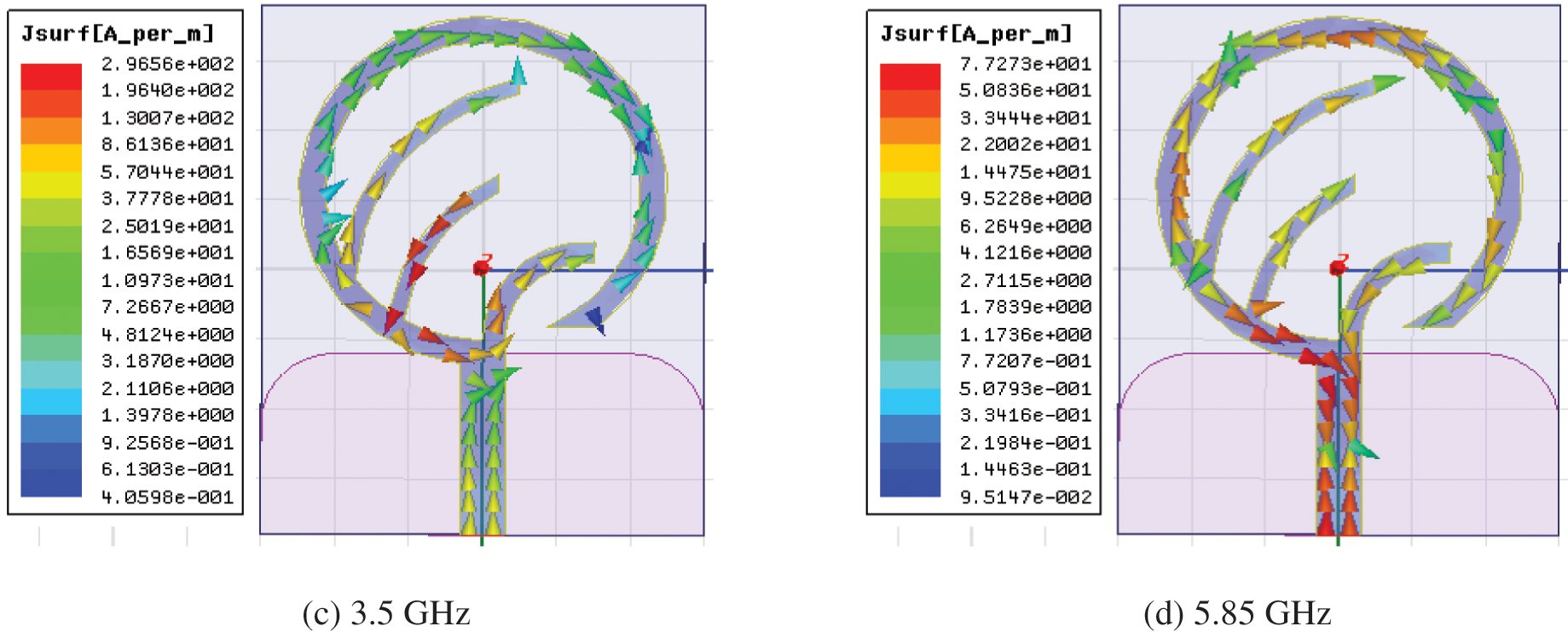
Figure 5: Surface current distribution of the proposed antenna at different frequency bands
Hence, strip-1 is responsible for the radiation of GSM 900 band, while strips-2 and 3 are responsible for WiMAX 2.5/3.5 bands, respectively. However, strip-4 in combination with the feed line is responsible for the radiation at 5.85 GHz of WLAN band. To experimentally validate the analysis based on the simulation results made in Section 2, a prototype of the proposed antenna is fabricated as shown in Fig. 6. Various antenna parameters are experimentally measured to compare its performance in comparison to the simulated results. The return loss of the fabricated prototype is measured using Agilent make VNA (Vector Network Analyzers) and the same is plotted along with the simulated result in Fig. 7. From the plot it can be observed that the measured result shows a quad-band characteristic in closed agreement with the simulated result. At the four operating bands, minimum values of S11 are measured as −36 dB at 940 MHz, −25 dB at 2.4 GHz, −37 dB at 3.3 GHz and −53 dB at 5.8 GHz. The slight deviation between simulated and measured return loss characteristics is observed, primarily due to the connector mismatch and the antenna fabrication error.
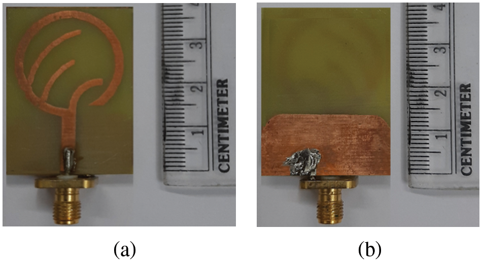
Figure 6: Fabricated prototype of the proposed modified sickle-shaped monopole antenna
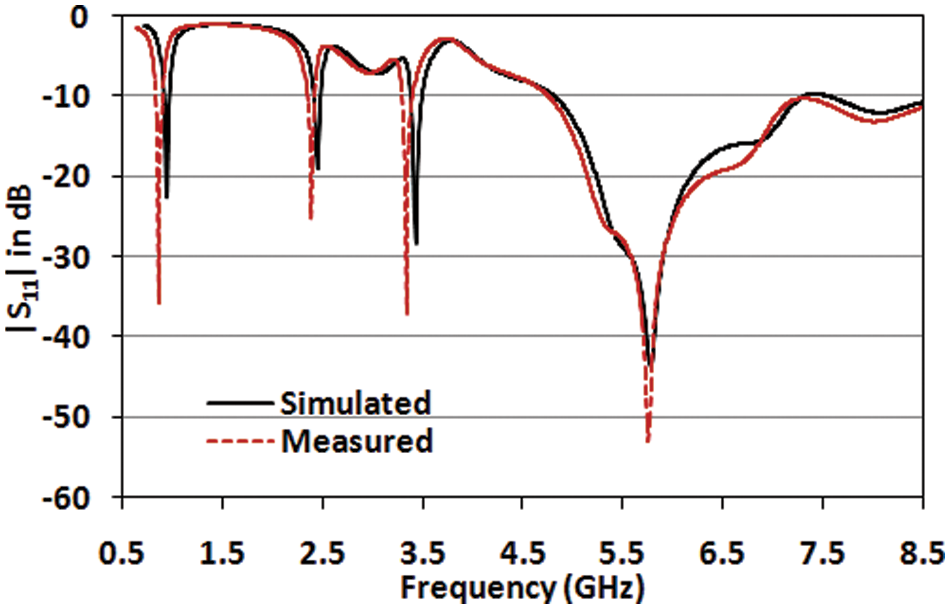
Figure 7: Plot of simulated and measured return loss of the proposed Quad-Band Antenna
The radiation pattern of the fabricated antenna is also measured by gain transfer method. The measurement setup consists of Hittite HMC-T2100 Microwave Signal Generator (10–20 GHz), a Krytar 9000B Power Meter and a standard gain Horn antenna. At different resonant frequencies, the comparative plots of the simulated and measured co-pol and cross-pol characteristics of the proposed antenna at two principal planes - E-plane and H-plane are depicted in Figs. 8a–8h. For GSM 900 band, the radiation pattern depicts that the simulated E-plane co-pol gain is 4.2 dBi while its measured value is 4.1 dBi. For the H-plane, the corresponding values are 2.9 and 2.7 dBi respectively. For the use of the proposed antenna for WiMAX frequency of 2.5/3.5 GHz, the antenna exhibits simulated and measured values of E-plane co-pol gain as 2.5 and 2.2 dBi respectively at 2.5 GHz and for the H-plane, those corresponding values are both 1.5 dBi. At 3.5 GHz, the simulated and measured values of E-plane co-pol gain as seen to be 1.7 dBi and 1.3 dBi, respectively with their corresponding H-plane values being 0.8 and 0.7 dBi, respectively.


Figure 8: Plot of simulated and measured radiation pattern of the proposed antenna at different resonant frequencies [S-Simulated value, M-Measured value]. E-plane radiation pattern: (a) f = 940 MHz, (c) f = 2.5 GHz, (e) f = 3.5 GHz, (g) f = 5.85 GHz. H-plane radiation pattern: (b) f = 940 MHz, (d) f = 2.5 GHz, (f) f = 3.5 GHz, (h) f = 5.85 GHz
Also for the use of antenna at WLAN frequency of 5.85 GHz, the simulated E-plane co-pol gain obtained is 1.9 dBi while its measured value is found to be 1.4 dBi. The corresponding H-plane co-pol simulated and measured values are 1.8 and 1.0 dBi respectively. The cross-pol values at the different resonant frequencies are found to be 20–30 dBi below their co-pol values. Tab. 2 depicts the values of antenna gain in both E-plane and H-plane for all the resonating frequencies. Hence the antenna exhibits good gain and radiation pattern at the designed frequency of operation which reflects its aptness for GSM 900/WiMAX/WLAN frequency bands. Performance of the proposed Compact Quad-Band sickle-shaped Monopole Antenna is compared with other relevant antennas available in the literature are enlisted in Tab. 3. It can be seen that compared to the reported antennas mentioned in the table, the proposed antenna prototype is functional at a lowermost operating frequency band centering at 940 MHz. The designed quad-band antenna covering lowermost frequency band offers satisfactory gain with acceptable bandwidth characteristics.


A novel quad-band monopole antenna with four sickle-shaped strips for GSM 900/WLAN/WiMAX applications has been proposed. The four sickle-shaped monopole strips enable the proposed antenna to generate four different resonating frequencies (940 MHz, 2.4/2.5, 3.5 and 5.85 GHz bands) to cover the desired bands of operation. Each sickle-shaped strip and the coupling between the strips contribute to the exact operating band. The measured results show that the antenna has good radiation pattern with proper gain so as to find its suitability for GSM 900, WiMAX and WLAN applications. Thus the proposed antenna would surely unfold new vistas for the scientific and technological community worldwide.
Acknowledgement: The authors gracefully acknowledge the support provided by Visvesvaraya PhD scheme, Ministry of Electronics and Information Technology (MeiTy), Govt. of India, Grant No. PhD-MLA/4(29)/2015–16/01.
Funding Statement: The authors received no specific funding for this study.
Conflicts of Interest: The authors declare that they have no conflicts of interest to report regarding the present study.
1. A. Abdalrazik, A. Gomaa, and A. A. Kishk, “A hexaband quad-circular-polarization slotted patch antenna for 5G, GPS, WLAN, LTE, and radio navigation applications,” IEEE Antennas and Wireless Propagation Letters, vol. 20, no. 8, pp. 1438–1442, 2021. [Google Scholar]
2. M. P. Singh, R. K. Jaiswal, K. V. Srivastava and S. Ghosh, “A compact triband circularly polarized meander-loaded monopole antenna,” Microwave and Optical Technology Letters, vol. 64, no. 2, pp. 382–388, 2021. [Google Scholar]
3. K. Mondal, “Half cutting dual-band circularly polarized monopole antenna for wireless communications,” AEU International Journal of Electronics and Communications, vol. 142, no. 154012, 2021. http://dx.doi.org/10.1016/j.aeue.2021.154012. [Google Scholar]
4. V. Remya, M. Abraham, A. Parvathy, and T. Mathew, “Multiband circularly polarised microstrip patch antenna with minkowski fractal slot for wireless communications,” Progress in Electromagnetics Research C, vol. 116, pp. 65–80, 2021. [Google Scholar]
5. M. Shakir, S. Aslam, M. U. Sarwar, M. Adnan, and M. R. Khan., “Performance evaluation and design of 5G communication-based millimeter wave antenna,” EURASIP Journal on Wireless Communications and Networking, vol. 179, 2021. http://dx.doi.org/10.1186/s13638-021-02052-9. [Google Scholar]
6. A. D. Boursianis, M. S. Papadopoulou, J. Pierezan, V. C. Mariani et al., “Multiband patch antenna design using nature-inspired optimization method,” IEEE Open Journal of Antennas and Propagation, vol. 2, pp. 151–162, 2020. [Google Scholar]
7. R. Pandey, A. K. Shankhwar, and A. Singh, “Design, analysis, and optimization of dual side printed multiband antenna for RF energy harvesting applications,” Progress in Electromagnetics Research C, vol. 102, pp. 79–91, 2020. [Google Scholar]
8. A. El Yassini, S. Ibnyaich, S. Chabaa and A. Zeroual, “Miniaturized broadband-multiband planar antenna with a symmetric quarter-circular ground plane for WLAN/WiMAX standards,” Microwave and Optical Technology Letters, vol. 62, no. 9, pp. 2953–2964, 2020. [Google Scholar]
9. N. Sharma and S. S. Bhatia, “Design of printed UWB antenna with CPW and microstrip-line-fed for DCS/PCS/Bluetooth/WLAN wireless applications,” International Journal of RF and Microwave Computer-Aided Engineering, vol. 31, no. 1, 2021. http://dx.doi.org/10.1002/mmce.22488. [Google Scholar]
10. A. K. Saroj and J. A. Ansari, “A reconfigurable multiband rhombic shaped microstrip antenna for wireless smart applications,” International Journal of RF and Microwave Computer-Aided Engineering, vol. 30, no. 10, 2020. http://dx.doi.org/10.1002/mmce.22378. [Google Scholar]
11. S. Chetal, A. K. Nayak, and R. K. Panigrahi, “Multiband antenna for WLAN, WiMAX and future wireless applications,” in The Proc. of URSI AP-RASC 2019, New Delhi, India, March 2019. [Google Scholar]
12. K. K. Naik, G. Dattatreya, R. Palla, and S. S. Rani, “Enhancement of gain with corrugated Y-shaped patch antenna for triple-band applications,” International Journal of RF and Microwave Computer-Aided Engineering, vol. 29, no. 3, 2019. http://dx.doi.org/10.1002/mmce.21624. [Google Scholar]
13. A. K. Gautam, L. Kumar, B. K. Kanaujia, and K. Rambabu, “Design of compact F-shaped slot triple-band antenna for WLAN/WiMAX applications,” IEEE Trans. on Antennas and Propagation, vol. 64, no. 3, pp. 1101–1105, 2016. [Google Scholar]
14. A. R. Jalali, J. Ahamdi-Shokouh, and S. R. Emadian, “Compact multiband monopole antenna for UMTS, WiMAX, and WLAN applications,” Microwave and Optical Technology Letters, vol. 58, no. 4, pp. 844–847, 2016. [Google Scholar]
15. M. Moosazadeh, and S. Kharkovsky, “Compact and small planar monopole antenna with symmetrical L- and U-shaped slots for WLAN/WiMAX applications,” IEEE Antennas and Wireless Propagation Letters, vol. 13, pp. 388–391, 2014. [Google Scholar]
16. Z. Zhang, Y. C. Jiao, Y. Song, T. L. Zhang, S. M. Ning et al., “A modified CPW-fed monopole antenna with very small ground for multiband WLAN applications,” Microwave and Optical Technology Letters, vol. 52, no. 2, pp. 463–466, 2010. [Google Scholar]
17. L. Kang, Y. Z. Yin, H. Li, W. J. Huang and S. F. Zheng, “Dual-wideband symmetrical G-shaped slotted monopole antenna for WLAN/WiMAX applications,” Progress in Electromagnetic Research Letters, vol. 17, pp. 55–65, 2010. [Google Scholar]
18. Q. Zhao, S. X. Gong, W. Jiang, B. Yang and J. Xie, “Compact wide-slot tri-band antenna for WLAN/WiMAX applications,” Progress in Electromagnetics Research Letters, vol. 18, pp. 9–18, 2010. [Google Scholar]
19. Y. Song, Y. C. Jiao, H. Zhao, Z. Zhang, Z. B. Weng et al., “Compact printed monopole antenna for multiband WLAN applications,” Microwave and Optical Technology Letters, vol. 50, no. 2, pp. 365–367, 2008. [Google Scholar]
20. H. Ma, Q. X. Chu and Q. Zhang, “Compact dual-band printed monopole antenna for WLAN application,” Electronics Letters, vol. 44, no. 14, pp. 834–835, 2008. [Google Scholar]
21. L. N. Zhang, S. S. Zhong, X. L. Liang and C. -H. Li, “Compact meander monopole antenna for tri-band WLAN application,” Microwave and Optical Technology Letters, vol. 49, no. 4, pp. 986–988, 2007. [Google Scholar]
22. J. H. Yoon, “Fabrication and measurement of modified spiral- patch antenna for use as a triple-band (2.4 GHz/5 GHz) antenna,” Microwave and Optical Technology Letters, vol. 48, no. 7, pp. 1275–1279, 2006. [Google Scholar]
23. V. Deepu, K. R. Rohith, J. Manoj, M. N. Suma, K. Vasudevan et al., “Compact uniplanar antenna for WLAN applications,” Electronics Letters, vol. 43, no. 2, pp. 70–72, 2007. [Google Scholar]
24. H. Yang and S. Yan, “A novel P-shaped printed monopole antenna for RFID applications,” Microwave and Optical Technology Letters, vol. 51, no. 2, pp. 554–556, 2009. [Google Scholar]
25. W. S. Chen and Y. H. Yu, “The design of printed rhomb shaped antenna with slits for WIMAX systems,” Microwave and Optical Technology Letters, vol. 49, no. 10, pp. 2503–2508, 2007. [Google Scholar]
26. C. H. Lee and S. O. Park, “A compact printed hook-shaped monopole antenna for 2.4/5-GHz WLAN applications,” Microwave and Optical Technology Letters, vol. 48, no. 2, pp. 327–329, 2006. [Google Scholar]
27. C. Y. Pan, C. H. Huang and T. S. Horng, “A new printed G-shaped monopole antenna for dual-band WLAN applications,” Microwave and Optical Technology Letters, vol. 45, no. 4, pp. 295–297, 2005. [Google Scholar]
28. W. C. Liu, W. R. Chen, and C. M. Wu, “Printed double S-shaped monopole antenna for wideband and multiband operation of wireless communication,” IEE Proceedings - Microwave, Antennas and Propagation, vol. 151, no. 6, pp. 473–476, 2004. [Google Scholar]
29. Y. L. Kuo and K. L. Wong, “Printed double-T monopole antenna for 2.4/5.2 GHz dual-band WLAN operations,” IEEE Transaction Antennas Propagation, vol. 51, no. 9, pp. 2187–2192, 2003. [Google Scholar]
30. Y. F. Lin, H. D. Chen and H. M. Chen, “A Dual-band printed L-shaped monopole for WLAN applications,” Microwave and Optical Technology Letters, vol. 37, no. 3, pp. 214–216, 2003. [Google Scholar]
31. S. H. Yeh and K. L. Wong, “Dual-band F-shaped monopole antenna for 2.4/5.2 GHz WLAN application,” in IEEE Antennas and Propagation Society Int. Symp., San Antonio, TX, USA, vol. 4, pp. 72–75, 2002. [Google Scholar]
32. K. G. Thomas and M. Sreenivasan, “A novel triple band printed antenna for WLAN/WiMAX applications,” Microwave and Optical Technology Letters, vol. 51, no. 10, pp. 2481–2485, 2009. [Google Scholar]
33. K. L. Wong and L. C. Chou, “Internal composite monopole antenna for WLAN/WiMAX operation in a laptop computer,” Microwave and Optical Technology. Letters, vol. 48, no. 5, pp. 868–871, 2006. [Google Scholar]
34. H. Q. Zhai, Z. H. Ma, Y. Han and C. H. Liang, “A compact printed antenna for triple band WLAN/WiMAX applications,” IEEE Antennas Wireless Propagation .Letters, vol. 12, pp. 65–68, 2013. [Google Scholar]
35. J. H. Yoon, “Fabrication and measurement of a monopole antenna with three arc-shaped strips for WLAN/WiMAX applications,” Microwave and Optical Technology Letters, vol. 56, no. 9, pp. 2061–2066, 2014. [Google Scholar]
36. K. He, R. X. Wang, Y. F. Wang and B. H. Sun, “Compact Tri-band claw shaped monopole antenna for WLAN/WiMAX applications,” Journal of Electromagnetic Waves and Applications, vol. 25, pp. 869–877, 2011. [Google Scholar]
37. J. Han and W. Ding, “A novel printed monopole antenna for dual-band WLAN application,” in Proc. of. Int. Conf. on Wireless Communications & Signal Processing, Nanjing, China, pp. 13–15, Nov. 2009. [Google Scholar]
38. C. A. Balanis, in Antenna Theory: Analysis and Design, 4th ed., Wiley, 2016, New York. [Google Scholar]
 | This work is licensed under a Creative Commons Attribution 4.0 International License, which permits unrestricted use, distribution, and reproduction in any medium, provided the original work is properly cited. |