DOI:10.32604/cmc.2022.026557
| Computers, Materials & Continua DOI:10.32604/cmc.2022.026557 | |
| Article |
Two-Stage High-Efficiency Encryption Key Update Scheme for LoRaWAN Based IoT Environment
1Department of Electrical Engineering, Tunghai University, Taichung, 407, Taiwan
2Research Center for Smart Sustainable Circular Economy, Tunghai University, Taichung, 407, Taiwan
3Department of Computer and Information Sciences, Chinese Military Academy, Kaohsiung, 830, Taiwan
4Department of Computer Science, Tunghai University, Taichung, 407, Taiwan
5Emergency Response Management Center, Industry-Academia Collaboration and University Extension Division, Ming-Chuan University, Taipei, 111, Taiwan
*Corresponding Author: Kun-Lin Tsai. Email: kltsai@thu.edu.tw
Received: 30 December 2021; Accepted: 02 March 2022
Abstract: Secure data communication is an essential requirement for an Internet of Things (IoT) system. Especially in Industrial Internet of Things (IIoT) and Internet of Medical Things (IoMT) systems, when important data are hacked, it may induce property loss or life hazard. Even though many IoT-related communication protocols are equipped with secure policies, they still have some security weaknesses in their IoT systems. LoRaWAN is one of the low power wide-area network protocols, and it adopts Advanced Encryption Standard (AES) to provide message integrity and confidentiality. However, LoRaWAN's encryption key update scheme can be further improved. In this paper, a Two-stage High-efficiency LoRaWAN encryption key Update Scheme (THUS for short) is proposed to update LoRaWAN's root keys and session keys in a secure and efficient way. The THUS consists of two stages, i.e., the Root Key Update (RKU) stage and the Session Key Update (SKU) stage, and with different update frequencies, the RKU and SKU provide higher security level than the normal LoRaWAN specification does. A modified AES encryption/decryption process is also utilized in the THUS for enhancing the security of the THUS. The security analyses demonstrate that the THUS not only protects important parameter during key update stages, but also satisfies confidentiality, integrity, and mutual authentication. Moreover, The THUS can further resist replay and eavesdropping attacks.
Keywords: Key update; AES; LoRaWAN; IoT security; high efficiency
Due to the rapid developments of Internet of Things (IoT), Artificial Intelligence (AI), and communication technologies, in recent years, IoT applications have been built for different fields. For example, an IoT system can be used in industry and medical treatment, and forms the so-called Industrial Internet of Things (IIoT) [1] and Internet of Medical Things (IoMT) [2] systems. For human daily lives, a smart home system [3] and a smart city [4] can also be created by combining IoT and AI technologies. In an IoT system, massive sensors are linked to network via wired and wireless connections, and then sensed data are delivered to control center, so that the corresponding operations can be performed.
In order to provide mass, wide-range and low-power connections, the concept of Low Power Wide Area Network (LPWAN) communication structure is established. In the past decade, many LPWAN communication systems have been proposed, e.g., Narrow Band IoT (NB-IoT) [5], Long Range Wide-Area Network (LoRaWAN) [6], Sigfox [7], DASH7 [8], etc. Due to business and research reason, many NB-IoT and LoRaWAN related studies have been proposed. To allow mass IoT devices to communicate with each other, NB-IoT utilizes licensed telecommunication bands, while LoRaWAN uses unlicensed band. Generally, both NB-IoT and LoRaWAN have the features of wide-area and low-energy communication. Moreover, LoRaWAN is an evolving protocol and can be used for many modern IoT environments.
The IoT security is as important as general computer and network security since its applications relate to businesses, industries, cities, and even human healthcare [9,10]. Providing information confidentiality, data integrity, and device availability becomes an essential requirement for LPWAN communication systems. The Advanced Encryption Standard (AES) [11] is adopted by LoRaWAN to ensure the transmitted data can be safely delivered from sender to receiver. Besides, two types of session keys are utilized in AES data encryption and decryption processes between end-devices and servers [12].
Even though LoRaWAN uses AES to protect the security of transmitted data, it still exists some security problems that need to be solved [13–15]. For example, LoRaWAN's root keys are kept in join-server and end-devices, but lack their own update mechanisms. Once the root keys are stolen, LoRaWAN's security might be crashed. Besides, the session keys are updated through the end-device re-join process which may also lead to device management and data consistency problems.
In order to deal with the key management and update problem, in this study, a Two-stage High-efficiency LoRaWAN key Update Scheme (THUS for short) is proposed to update LoRaWAN's root keys and session keys in a secure and efficient way. The THUS utilizes modified AES process and system time stamp to achieve the goal of mutual authentication, confidentiality and message integrity during its update procedure. Besides, the security analysis also shows that the THUS has the ability to resist replay and eavesdropping attacks. In the THUS, the root key and session key can be renewed without changing the device information recorded in join-server, network-server, and application-server. Besides, with different key update frequencies, the THUS provides higher security level than the conventional LoRaWAN specification does. The main contributions of this paper are listed below.
(i) The proposed THUS improves LoRaWAN key management by updating both root keys and session keys.
(ii) The modified AES algorithm is utilized in the THUS so that the security of key update procedure can be enhanced and the processing performance can also be improved.
(iii) During the key update procedure, the proposed THUS provides the features of mutual authentication, confidentiality and message integrity and has the ability to resist eavesdropping attack and replay attack.
The remaining part of this paper is organized as follows. LoRaWAN security policy and some IoT-related studies are introduced in Section 2. Then, Section 3 presents the detailed process of the THUS, including the Root Key Update (RKU) stage and Session Key Update (SKU) stage. The security analyses and discussion are presented in Section 4. Section 5 addresses the THUS performance. Section 6 concludes this study and points out our future study.
Since LoRaWAN is one of the communication protocols designed for IoT applications, it provides many attractive features including low power and long-distance communication. The security policy of LoRaWAN [16,17] is established under the requirements of data confidentiality, mutual authentication between devices and servers, message integrity. Accordingly, AES cryptographic algorithm and two operation modes, i.e., Counter Mode (CTR) and Cipher-based Message Authentication Code (CMAC), are adopted in the LoRaWAN data transmission. The CTR is used for data encryption and decryption, while the CMAC is utilized to guarantee the message integrity. Besides, LoRaWAN uses two types of session keys to protect data security, one for end-devices and application-servers, namely application session key (AppSKey), and another for end-devices and network-servers, namely network session key (NwkSKey for R1.0, and FNwkSIntKey, SNwkSIntKey, NwKSEncKey for R1.1. To simplify, in this study, the NwkSKey is used to represent all network session keys). As shown in Fig. 1, when an end-device new joins to an IoT system, a globally unique identifier DevEUI and two unique root keys, including AppKey and NwkKey, are registered in join-server. And then, the join process between end-device and join-server generates two types of session keys by using DevEUI, AppKey and NwkKey. Following that, the NwkSKey and AppSKey are delivered to network-server and application-server, respectively.
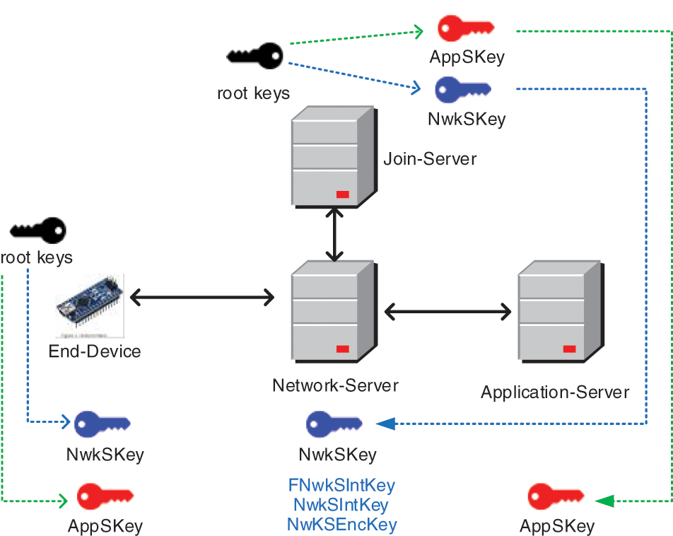
Figure 1: LoRaWAN uses two root keys to generate session keys
Since IoT security is an important topic for constructing an IoT system, many related studies [18–21] have been proposed in the past years. According to the announced LoRaWAN 1.0 protocol, Naoui et al. [18] pointed out two important parameters might be attacked. The first parameter is a 16-bit counter, DevNonce, which is used to record the join times of an end-device. Since the DevNonce is transmitted with unencrypted format, the replay attack might be launched by some attacker. The second parameter is AppNonce which is utilized for mutual authentication between application-server and end-device. An attacker may forge the join acceptance message sent by network server, retransmit the same message to the end-device, and then pretend to be a legitimate application-server. In [18], Naoui et al. utilized an independent computer to be the trusted third party and created a timeline for every message so that the session keys can be delivered to network-server and application-server in a secure way.
Eldefrawy et al. [19] checked the security policies of different LoRaWAN protocols. Similarly, they also claimed that the transmitted data will be disclosed when the parameter AppNonce in LoRaWAN v1.0 is known by attackers. However, LoRaWAN v1.1 utilized join-server to generate and dispatch session keys, hence enhanced the security level. Even though LoRaWAN improves its security in v1.1, many researchers still think the root key management is a drawback of LoRaWAN's security policy.
Chen et al. [20] proposed a comprehensive LoRaWAN key management scheme, which addressed key updating, key generation, key backup, and key backward compatibility. The centralized key management server designed in [20] was a trusted agent dealing with the whole lifecycle of the key management, i.e., key generation/derivation, updating, backup/recovery, and key revocation. Compared with other previous studies, they provided a good and secure solution for LoRaWAN key management. However, involving an extra server may also lead to other security problems. Xing et al. [21] used elliptic curve cryptography for root key update scheme. Both end-devices and server adopted the hierarchical deterministic wallet to manage the key pair, and the key agreement between the end-devices and the server was realized by the elliptic curve Diffie-Hellman key exchange algorithm. They also used bi-directional Hash algorithm during communication. Although their method indeed enhanced the security of LoRaWAN key management, the complex elliptic curve cryptography algorithm consumed much power during key update procedure.
Dönmez et al. [22] utilized a master device to store the original root keys of end-devices so as to enhance the LoRaWAN's security. The connections between master device and end-devices are physical links, as a result, the master device can be considered as an extension part of end-devices. Moreover, the master device can also be utilized to charge the batteries of end-devices. However, when master device was hacked, it may result in serious problem of whole IoT system.
Because original root keys are stored in end-devices, and in LoRaWAN standard, only session key can be update by using rejoin process; however, the root keys cannot be update. In [23], Han and Wang created a root key update method by using key derivation function to solve the key management problem. Their experiment showed that the key generation process can generate new root keys with very high degree of randomness.
3 Two-Stage LoRaWAN Key Update Scheme
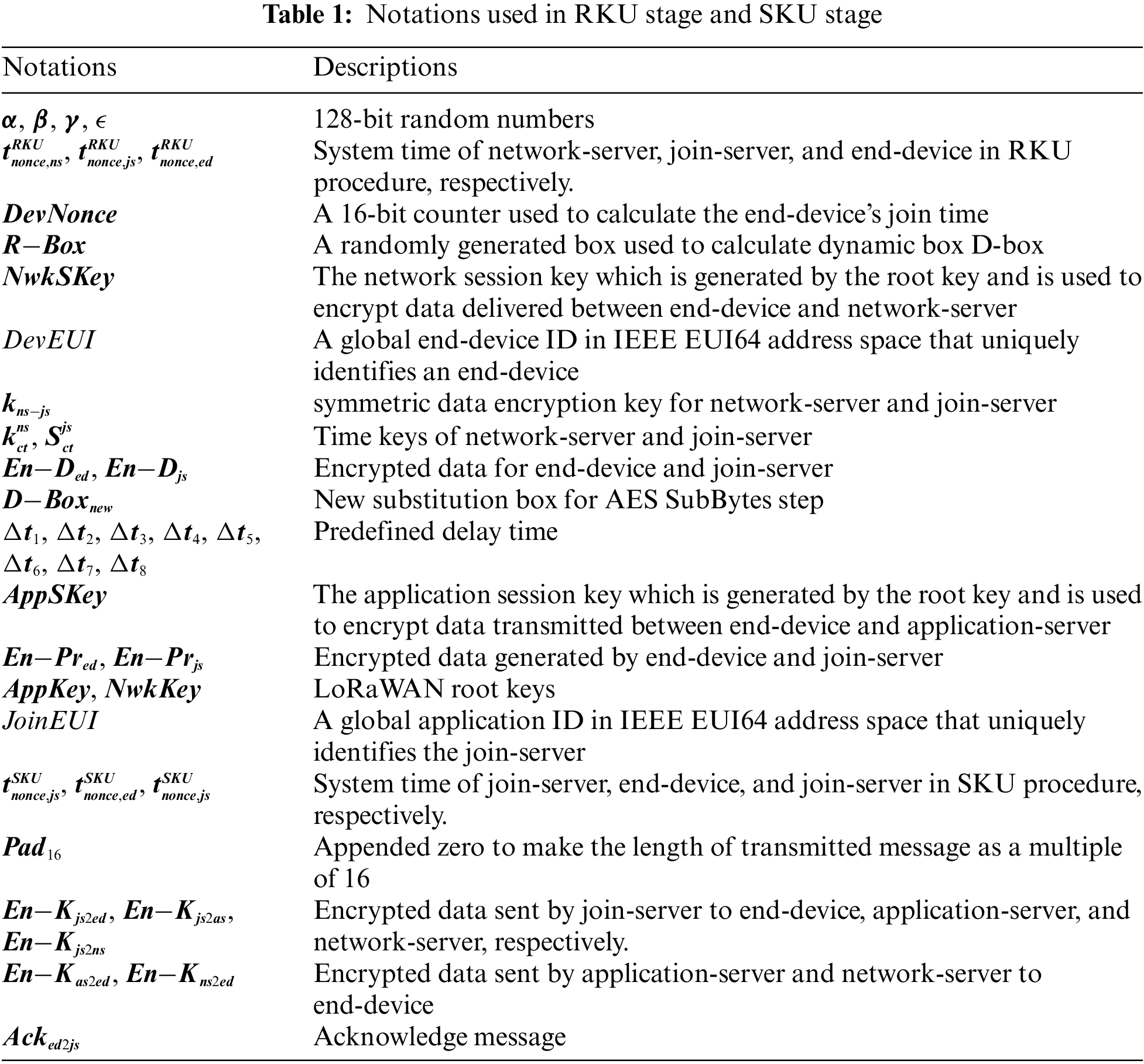
As abovementioned, LoRaWAN's protocols [16,17] do not take root key management into account. Once the root keys are attacked and stolen, it can easily induce security problems. In this section, as shown in Fig. 2, a two-stage LoRaWAN key update scheme is proposed. The first one is root key update (RKU) stage, and the second one is session key update (SKU) stage. In Section 3.1, the modified AES is introduced so as to enhance the security level and reduce the computational complexity at the same time. Then, the detailed steps of RKU stage and SKU stage are described in Sections 3.2 and 3.3, respectively. The notations used in the RKU and SKU stage are illustrated and defined in Tab. 1.
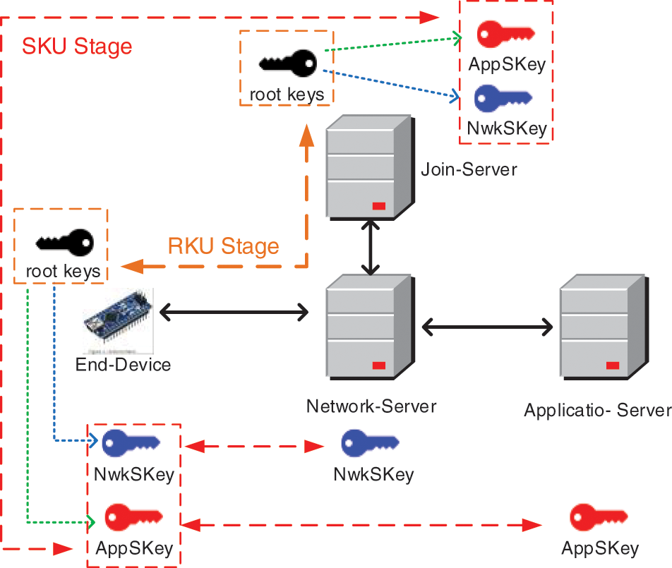
Figure 2: Root keys are updated in RKU stage and session keys are updated in SKU stage
In order to improve AES's security strength and operating speed, a dynamic-box (D-Box) is designed to replace the original substitution-box (S-Box). The enhanced dynamic accumulated shifting substitution (EDASS) algorithm proposed in [24] and used in [25] is a randomized function which can be used to generate irreversible text. The EDASS based D-Box Generation (DBG) process uses three inner keys and three insertion arrays to generate a D-Box. During the RKU and SKU stage, the inputs of modified AES are plaintext and a D-Box, and the corresponding output is a ciphertext. Besides, a flag array is also utilized to prevent duplicate elements appear in the D-Box. For security reason, the D-Box is required irregular renewal. In this study, the D-Box of modified AES has 256 elements, which means that a total number of 256! (=
3.2 Stage 1: Root Key Update Procedure
In the RKU stage, there are three important parameters, i.e.,
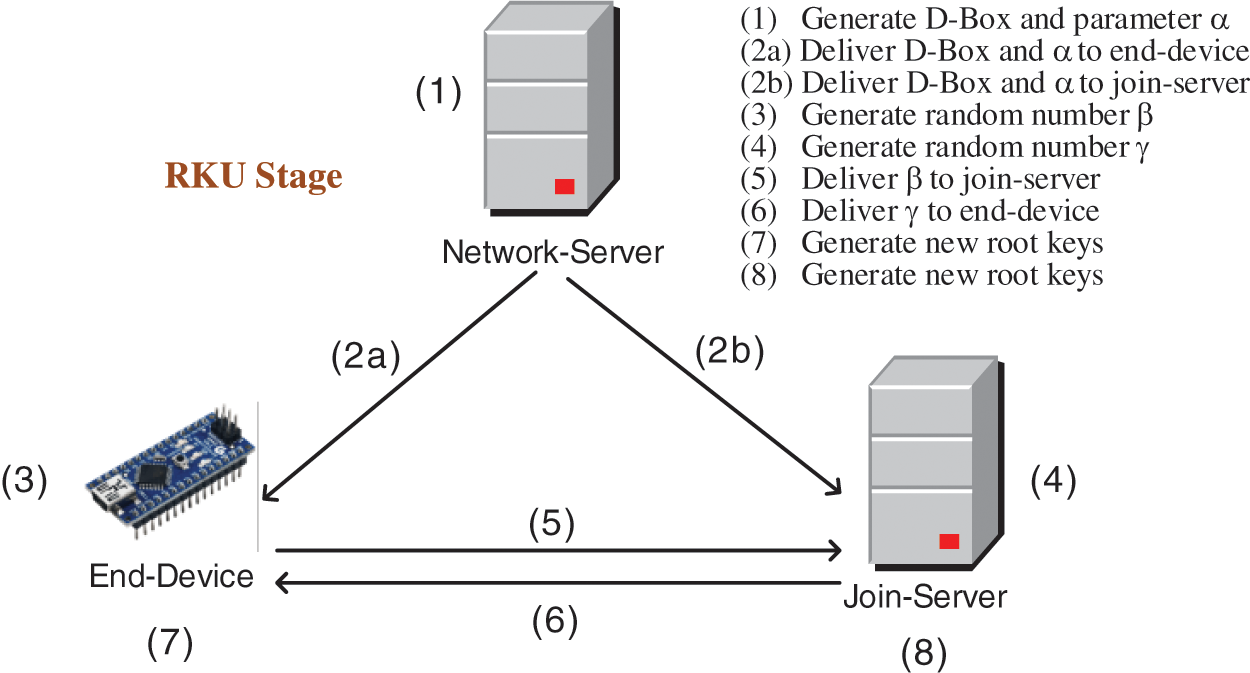
Figure 3: There are 8 steps in the RKU stage
Step (1): The network-server performs the following sub-steps.
(1.1) generates a random box
(1.2) fetches the system time
(1.3) calculates the time key
(1.4) calculates new AES substitution box
(1.5) calculates
(1.6) calculates
Step (2a): The network-server delivers
Step (2b): The network-server delivers
Step (3): When receiving
(3.1) calculates
(3.2) takes the system time
(3.3) according to DevEUI, retrieves the corresponding DevNonce, calculates
(3.4) generates a random number
(3.5) calculates
Step (4): When receiving
(4.1) calculates
(4.2) takes the system time
(4.3) according to DevEUI, retrieves the corresponding DevNonce, calculates
(4.4) generates a random number
(4.5) calculates
Step (5): The end-device sends
Step (6): The join-server sends
Step (7): When receiving
(7.1) calculates
(7.2) takes the system time
(7.3) verifies
(7.4) computes new root keys
Step (8): When receiving
(8.1) calculates
(8.2) takes the system time
(8.3) verifies
(8.4) computes new root keys which are the same with those equations in Step (7.4).
3.3 Stage 2: Session Key Update Procedure
In the SKU stage, once the join-server receives the session key update request sent by network-server, it generates an important parameter
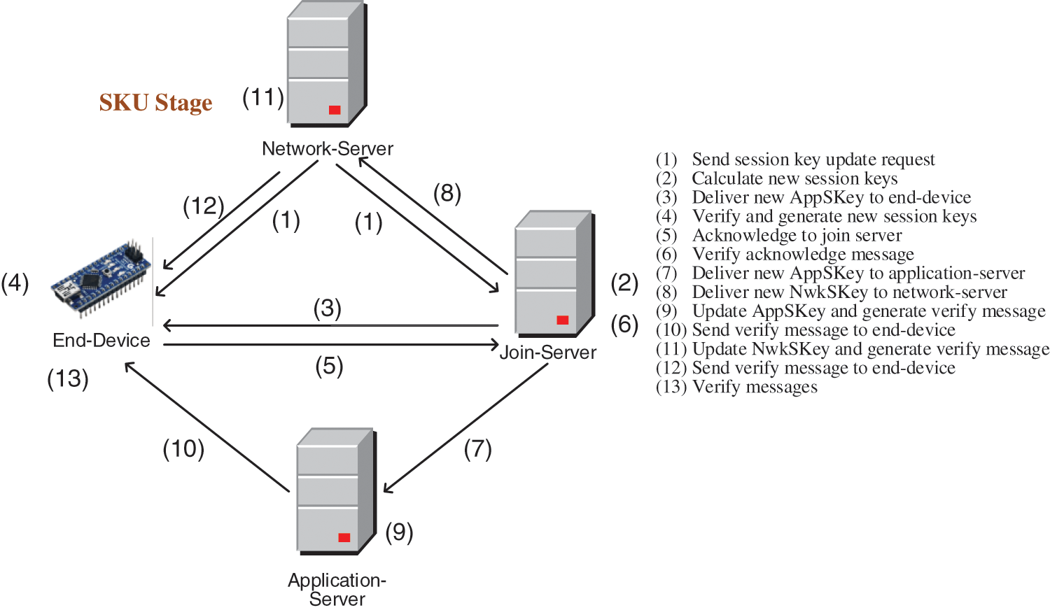
Figure 4: The SKU stage consists of 13 steps
Step (1): The network-server sends a SKU request and DevEUI to end-device and join-server.
Step (2): When receiving the SKU request, the join-server performs the following sub-steps.
(2.1) according to DevEUI, retrieves DevNonce (a 16-bit counter managed by end-device), JoinEUI (a global application ID in IEEE EUI64 address space that uniquely identifies the join-server), AppKey (one of the original root keys), and NwkKey (one of the original root keys) from its database;
(2.2) generates a 128-bit random number
(2.3) fetches system time
(2.4) calculates new session keys
(2.5) calculates
Step (3): The join-server delivers
Step (4): When receiving
(4.1) calculates
(4.2) obtains
(4.3) fetches system time
(4.4) calculates
(4.5) calculates new session keys with the equations same to those listed Step (2.4);
(4.6) calculates the acknowledgement message
Step (5): The end-device sends the acknowledge message
Step (6): Once receiving
(6.1) decrypts
(6.2) fetches system time
(6.3) checks to see whether
(6.4) calculates
(6.5) calculates
(6.6) calculates
Step (7): Join-server sends
Step (8): Join-server sends
Step (9): Once receiving
(9.1) decrypts
(9.2) fetches system time
(9.3) calculates
(9.4) updates session key
(9.5) calculates
Step (10): Application-server sends
Step (11): On receiving
(11.1) decrypts
(11.2) fetches system time
(11.3) calculates
(11.4) updates session keys
(11.5) calculates
Step (12): Application-server sends
Step (13): On receiving
(13.1) decrypts
(13.2) decrypts
In this section, we analyze the security of THUS with Scyther tool [26] and discuss the security features of the THUS. The Scyther tool traces all parameters of the THUS, and checks whether these parameters are safe during transmission. The analyzed result is shown in Fig. 5, in which the important parameters are not threatened by attackers.
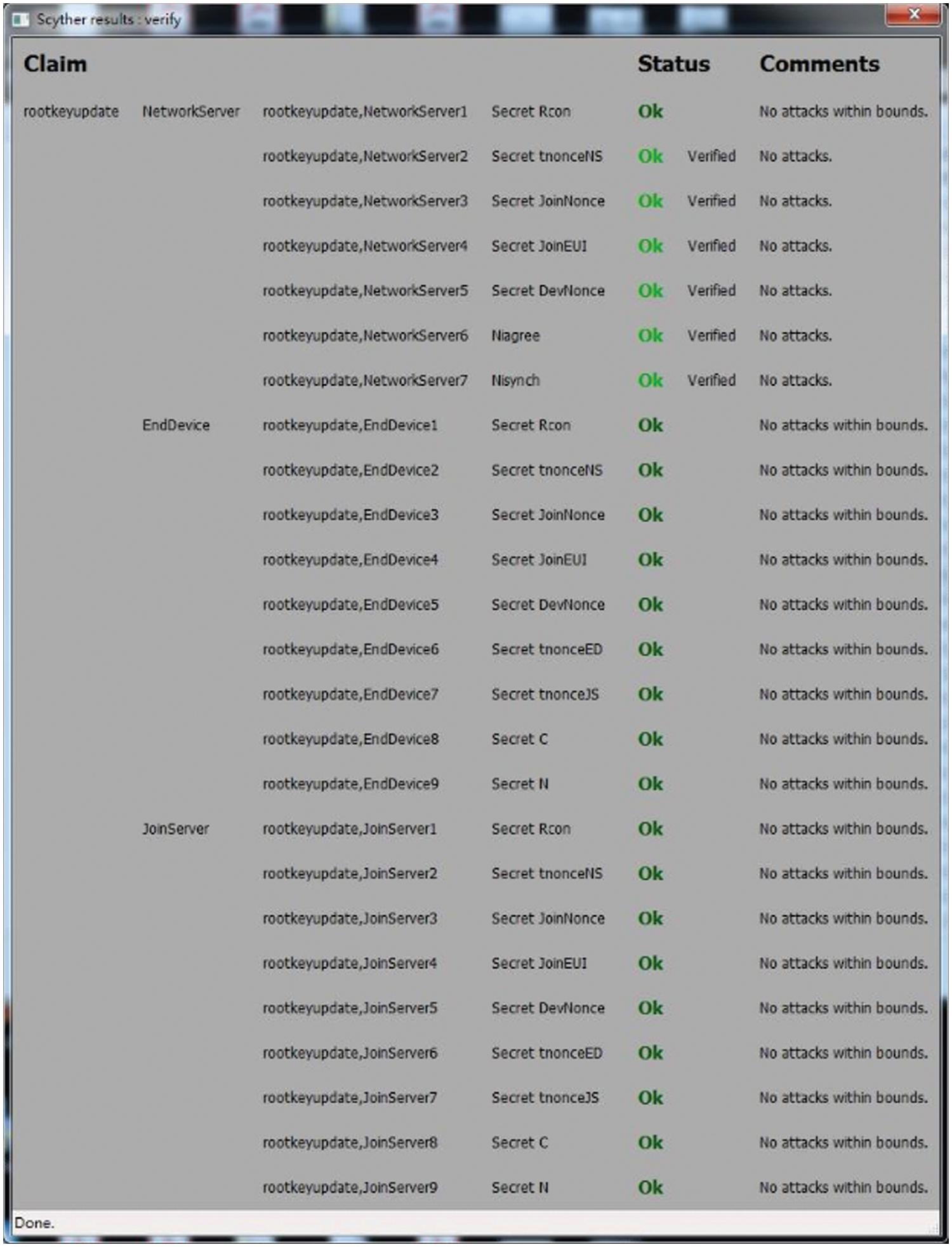
Figure 5: The analyzed result of the proposed THUS
The other THUS security features are discussed as follows.
• Mutual authentication indicates that the data transmission parties can authenticate with each other. In the RKU stage of the THUS, both DevEUI and DevNonce are used to guarantee the authenticities of each communication pair. When an attacker lacks correct DevNonce, the correct
• Confidentiality represents that the THUS has the ability to protect all important parameters. In the RKU stage and SKU stage of the THUS, all parameters become ciphertext by utilizing modified AES before transmission. In Steps (2a) and (2b) of RKU stage, the messages
• Message integrity feature makes sure the transmitted messages not be forged. In the THUS, eight message integrity patterns, i.e.,
• Resist replay attack means some attacker captures some messages delivered by sender, duplicates those messages, and then retransmit them to receiver so as to pretend to be the legal sender. In the THUS, both RKU and SKU stages utilize time parameters (tnonce) to resist replay attack. Before data transmission, the time parameter is encrypted and embedded in the transmitted message. As shown in steps (3.2), (4.2), (7.2), and (8.2) of the RKU and steps (4.3), (6.2), (9.2), and (11.2) of the SKU, when receiver receives the message, the time parameter is utilized to guarantee the transmission time shorter than a predefine time limit. Once the actual transmission time is longer than the predefined time limit, it indicates that the message may send by illegal part, which means it may suffer replay attack. Accordingly, the THUS has the ability to prevent the replay attack.
• Resist eavesdropping attack indicates that an attacker captures massive messages and tries to obtain important information from them. In the THUS, parameters α, β, γ, ε, and D-Box are the most important parameters. The former three parameters are generated randomly and the D-Box is also produced by utilizing random box R-Box via DBG algorithm. All of these parameters and D-Box are encrypted by using EDASS before transmission. Since these parameters vary in every RKU stage and SKU stage, attackers cannot extract any parameters from the captured messages.
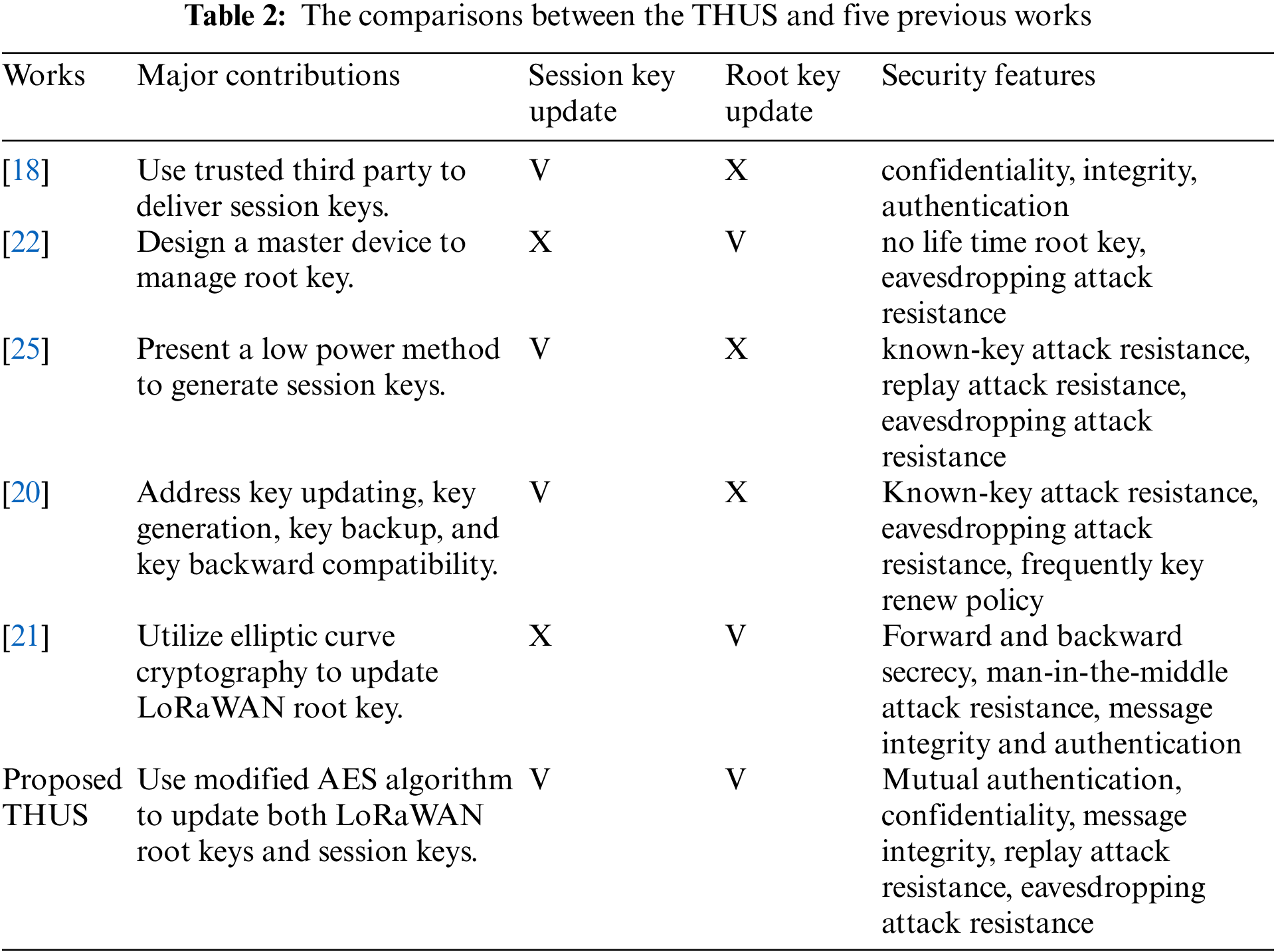
The comparisons between the proposed THUS and five previous works are listed in Tab. 2. As shown, the THUS equips not only root key update scheme, but also session key update scheme. By using modified AES algorithm, the THUS has the ability to provide high level security with efficient process.
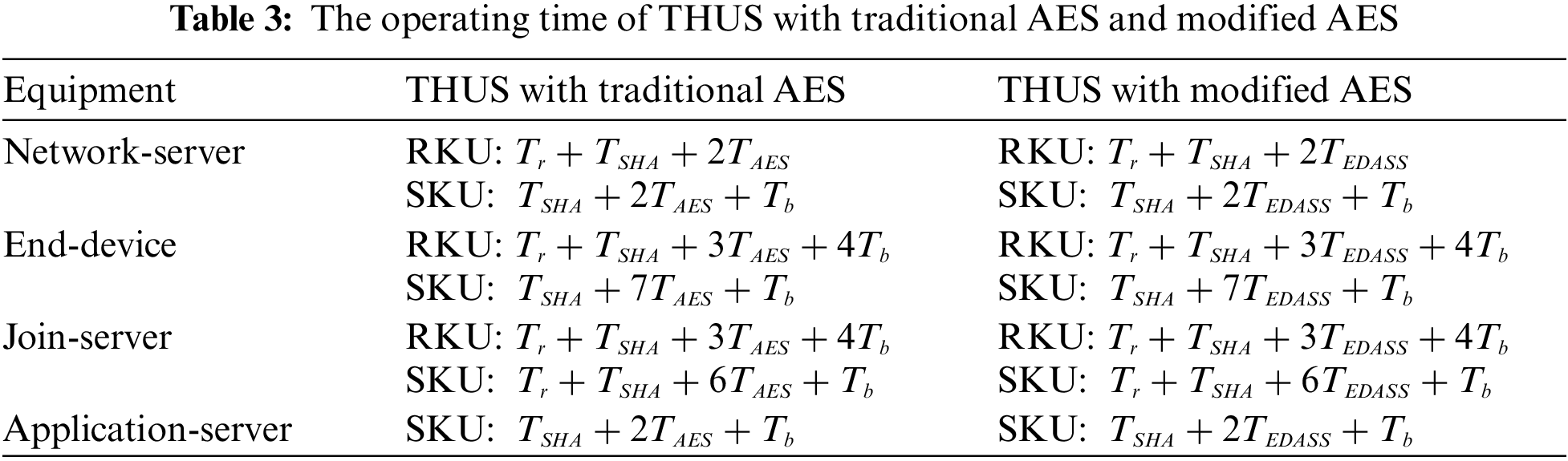
Tab. 3 lists the operating time of the THUS, where
6 Conclusion and Future Studies
Secure data communication is a basic requirement for every IoT system. Although LoRaWAN utilizes AES cryptography to achieve the goal of data integrity and confidentiality, the encryption key management can be further improved. In this paper, the THUS is proposed to update LoRaWAN's root keys and session keys so that the LoRaWAN's security scheme can be enhanced. The modified AES algorithm with dynamic substitution-box is utilized in both RKU stage and SKU stage. According to the security discussion above, the proposed THUS has the features of mutual authentication, confidentiality and message integrity, and can resist replay and eavesdropping attacks.
In the future, the formal security verification for the RKU and SKU will be performed. Besides, the implementation of THUS on a FPAG (Field Programmable Gate Array) system will also be developed so that the real performance can be evaluated. These constitute our future studies.
Funding Statement: The authors received no specific funding for this study.
Conflicts of Interest: The authors declare that they have no conflicts of interest to report regarding the present study.
1. H. Boyes, B. Hallaq, J. Cunningham and T. Watson, “The industrial internet of things (IIoTAn analysis framework,” Computers in Industry, vol. 101, pp. 1–12, 2018. [Google Scholar]
2. G. J. Joyia, R. M. Liaqat, A. Farooq and S. Rehman, “Internet of medical things (IoMTApplications, benefits and future challenges in healthcare domain,” Journal of Communications, vol. 12, no. 4, pp. 240–247, 2017. [Google Scholar]
3. K. L. Tsai, F. Y. Leu and I. You, “Residence energy control system based on wireless smart socket and IoT,” IEEE Access, vol. 4, pp. 2885–2894, 2016. [Google Scholar]
4. A. Kirimtat, O. Krejcar, A. Kertesz and M. F. Tasgetiren, “Future trends and current state of smart city concepts: A survey,” IEEE Access, vol. 8, pp. 86448–86467, 2020. [Google Scholar]
5. D. Flore, 3GPP Standards for the Internet-of-Thigs, GSMA MIoT, 2016. [Google Scholar]
6. LoRaWAN, Accessed: Dec. 20, 2021. [Online]. Available: https://www.lora-alliance.org/. [Google Scholar]
7. Sigfox, Accessed: Dec. 20, 2021. [Online]. Available: https://www.sigfox.com/. [Google Scholar]
8. DASH7, Accessed: Dec. 20, 2021. [Online]. Available: https://dash7-alliance.org/. [Google Scholar]
9. M. Alizadeh, K. Andersson and O. Schelén, “A survey of secure internet of things in relation to blockchain,” Journal of Internet Services and Information Security (JISIS), vol. 10, no. 3, pp. 47–75, 2020. [Google Scholar]
10. H. Hui, X. An, H. Wang, W. Ju, H. Yang et al., “Survey on blockchain for internet of things,” Journal of Internet Services and Information Security (JISIS), vol. 9, no. 2, pp. 1–30, 2019. [Google Scholar]
11. National Inst of Standards and Technology Gaithersburg MD, “Announcing the Advanced Encryption Standard (AES),” Federal Information Processing Standards Publication 197, United States National Institute of Standards and Technology (NIST2001. [Google Scholar]
12. K. L. Tsai, F. Y. Leu, L. L. Hung and C. Y. Ko, “Secure session key generation method for LoRaWAN servers,” IEEE Access, vol. 8, pp. 54631–54640, 2020. [Google Scholar]
13. H. Noura, T. Hatoum, O. Salman, J. P. Yaacoub and A. Chehab, “LoRaWAN security survey: Issues, threats and possible mitigation techniques,” Internet of Things, vol. 12, pp. 100303, 2020. [Google Scholar]
14. K. L. Tsai, F. Y. Leu, I. You, S. W. Chang, S. J. Hu et al., “Low-power AES data encryption architecture for a LoRaWAN,” IEEE Access, vol. 7, pp. 146348–146357, 2019. [Google Scholar]
15. I. You, S. Kwon, G. Choudhary, V. Sharma and J. T. Seo, “An enhanced LoRaWAN security protocol for privacy preservation in IoT with a case study on a smart factory-enabled parking system,” Sensors, vol. 18, no. 6, pp. 1888, 2018. [Google Scholar]
16. LoRa Alliance Technical Committee, LoRaWAN Backend Interfaces 1.0 Specification, LoRa Alliance, 2017. [Google Scholar]
17. LoRa Alliance Technical Committee, “LoRaWAN 1.1 specification,” LoRa Alliance, 2017. [Google Scholar]
18. S. Naoui, M. E. Elhdhili and L. A. Saidane, “Trusted third party based key management for enhancing LoRaWAN security,” in Proc. of IEEE/ACS 14th Int. Conf. on Computer Systems and Applications (AICCSA), Hammamet, Tunisia, pp. 1306–1313, 2017. [Google Scholar]
19. M. Eldefrawy, I. Butun, N. Pereira and M. Gidlund, “Formal security analysis of LoRaWAN,” Computer Networks, vol. 148, pp. 328–339, 2019. [Google Scholar]
20. X. Chen, M. Lech and L. Wang, “A complete key management scheme for LoRaWAN v1.1,” Sensors, vol. 21, no. 9, Article: 2962, pp. 1–20, 2021. [Google Scholar]
21. J. Xing, L. Hou, K. Zhang and K. Zheng, “An improved secure key management scheme for LoRa system,” in Proc. of IEEE 19th Int. Conf. on Communication Technology, Xi'an, China, pp. 296–301, 2019. [Google Scholar]
22. T. C. M. Dönmez and E. Nigussie, “Key management through delegation for LoRaWAN based healthcare monitoring systems,” in Proc. of 13th Int. Symp. on Medical Information and Communication Technology (ISMICT), Oslo, Norway, pp. 1–6, 2019. [Google Scholar]
23. J. Han and J. Wang, “An enhanced key management scheme for LoRaWAN,” Cryptography, vol. 2, no. 4, article 34, pp. 1–12, 2018. [Google Scholar]
24. J. J. Liu, Y. L. Huang, F. Y. Leu, X. Y. Pan and L. R. Chen, “Generating dynamic box by using an input string,” in Proc. of Int. Symp. on Mobile Internet Security, Jeju Island, Korea, pp. 1–13, 2017. [Google Scholar]
25. K. L. Tsai, Y. L. Huang, F. Y. Leu, I. You, Y. L. Huang et al., “AES-128 based secure low power communication for LoRaWAN IoT environments,” IEEE Access, vol. 6, pp. 45325–45334, 2018. [Google Scholar]
26. The Scyther Tool. Accessed: Jan. 25, 2022. [Online]. Available: https://people.cispa.io/cas.cremers/scyther/. [Google Scholar]
 | This work is licensed under a Creative Commons Attribution 4.0 International License, which permits unrestricted use, distribution, and reproduction in any medium, provided the original work is properly cited. |