DOI:10.32604/cmc.2022.028616
| Computers, Materials & Continua DOI:10.32604/cmc.2022.028616 | |
| Article |
Dual Band Switched Beam Textile Antenna for 5G Wireless Communications
1Department of Electrical Engineering, Srinakharinwirot University, Nakhon Nayok, 26120, Thailand
2Department of Telecommunication Engineering and Department of Electrical Engineering, Rajamangala University of Technology Isan (RMUTI), Nakhonratchasima, 30000, Thailand
3School of Electronic Engineering, Suranaree University of Technology, Nakhonratchasima, 30000, Thailand
*Corresponding Author: Pichaya Chaipanya. Email: pichayac@g.swu.ac.th
Received: 14 February 2022; Accepted: 18 March 2022
Abstract: This paper presents the single element dual band switched beam textile antenna. The antenna can operate at frequencies of 0.7 and 2.6 GHz using for 5G wireless communication applications. Textile fabric is considered to be used for substrate layer at the parts of a microstrip antenna for wireless body area network. The beam pattern of antenna can be switched into two directions by changing the position of shorted-circuit points at each edge of antenna. The main beam direction is 45°/225° when corner A is shorted while it steers at 135°/315° when corner B is shorted circuit. The advantage of the proposed antenna is the decrease of the problems like interference, light weight, flexibility and ability to switch beam easily. In addition, the results of the fabricated antenna are compared with the simulated ones. Moreover, the antenna is bent with curvature radius of 6 mm in forward direction. The effects of the bent antenna are studied. The results can confirm that radiation patterns of the bending antenna can be pointed into two directions when changing the positions of shorted circuit. Therefore, the proposed antenna can switch beam patterns, it is flexible, and it can operate at dual-band frequency on textile.
Keywords: Dual band; switched beam; textile; 5G wireless communications
Wireless Communication is growing fast in the communication field because wireless communication is a part of daily life. In order to manage the problems of the enormous increasing of demand in wireless communications, 5th generation (5G) wireless systems [1–4] are the proposed next wireless communication standards beyond the current 4th generation/International Mobile Telecommunications (4G/IMT)-advanced standards. The aims of 5G are allowing higher density of user, providing higher capacity than current 4G, etc. In 5G technology, the frequency spectrum is classified into several bands. Therefore, 5G antenna has a low complexity of implementation and can support multiband frequencies. In Thailand, The National Broadcasting and Telecommunications Commission has allocated frequency bands for 5G technology into three bands, which are 0.7, 2.6 and 26 GHz.
Antennas are usually designed on a rigid substrate for wireless applications. There are some examples from literature concerning a dual band antenna such as the work presented in [5]. The dual-band microstrip patch antenna with U-shaped slot fed by coaxial feeding technique has been revealed. The antenna can operate at frequencies of 2.4 and 4.6 GHz. In addition, the work presented in [6] has shown a dual band antenna that can operate at frequencies of 2.47 and 5.04 GHz. The antenna is switched beam antenna whose main beam directions can be switched by controlling the positions of shorted circuit at terminal edges. However, flexible material, which is suitable for integration into clothing, is the main requirement for wearable antenna in wireless body area network (WBAN) applications. Textile antennas made from cloth are the focus of several researches such as the work presented in [7], where the enhancing bandwidth of flexible-screen-printed antenna has been presented. The substrate used has been flexible Kapton material. The bandwidth has been increased by employing defected ground structure, which has provided a wideband of 1.77 to 6.95 GHz, working in the sub 7 GHz bands, such as the 5G applications. In addition, textile slot bow-tie antenna made from conductive polyester textile has been revealed in [8], where the antenna can operate in frequency range of 3.025 to 6.193 GHz. The substrate used for the textile antenna in [9] has been a synthetic paper material obtained from Teslin. The antenna has provided multiband, which has been separated into three bands: a low-frequency band for frequency range of 1.83 to 2.9 GHz, a mid-frequency band for frequency range of 3.4 to 3.6 GHz and a high-frequency band for frequency range of 4.6 to 5.8 GHz. Next, the fingernail antennas for 5G applications have been presented in [10]. Two antenna models have been fabricated for employment in two frequency bands, 15 and 28 GHz. Microstrip patch has been created by nanoparticle conductive silver ink. After that, copper layer has been added to the millimeter wave antenna. In addition, a dual-band textile planar inverted-F (PIFA) antenna able to operate in a dual frequency band, 2.4 and 5.2 GHz or 5.8 GHz has been presented in [11]. In addition, wearable dual-band and dual-polarized textile antenna has been proposed in [12]. The antenna has operated at 2.38 GHz for linear polarization for on-body while it has operated at 3.5 GHz for circular polarization for off-body communications. Moreover, the works presented in [13–17] have been focused on dual band textile antenna. In addition, in [18,19], the flexible antennas have been reviewed. Several shapes of antenna, materials and techniques to fabricate the flexible antenna have been presented.
Moreover, a technique that can improve the performance of 5G wireless communications is smart antenna technique [20,21]. Smart antenna can steer main beam direction to the desire direction while turning null or low side lobe to interference directions. Switched beam or fixed beam antenna is an attractive category of smart antenna due to its simple structure and low complex processing. There are three major parts of switched beam antenna: the (array) antenna, beamforming network and beam selector. The first step, fixed beams are steered to multiple directions and the signal strength of each direction is detected in process of beamforming network. Next, the beam direction that provides the maximum signal strength is selected in beam selector process when the position of the user is fixed while the beam direction is switched when the position of the user is moved. According to this, this system can increase the signal strength and reduce interference signals. Therefore, the performance of 5G wireless communications can be improved. Several researchers have proposed switched beam antenna for 5G wireless communications such as the work presented in [22]. Phase shifters for multi-beam for 5G technology at 26 GHz have been designed. Main beam directions of 0°, 45°, 90°, 135° and 180° can be turned. In addition, the antenna designed for 2.45 GHz, which has single active element at the center that has been surrounded by several symmetrically parasitic elements, has been revealed in [23]. Moreover, the sub array consists of four elements patch antenna then sub arrays are arranged on the sides of an octagonal prism, as revealed in [24]. The antenna can switch in three directions and operate at the frequencies of 28 and 38 GHz, which has been the millimeter-wave. In addition, in the work presented in [25], the antenna can operate in eight resonant frequencies, whose frequency range of 7–15 GHz works in 5G applications. Main beam directions can be switched into two different directions. The structure of multiband antenna has been low complex and simple of beam switching.
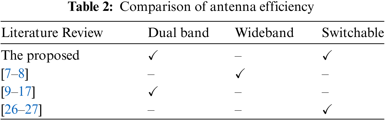
There are some examples from literature concerning a dual band textile antenna. Switched beam textile antenna for WBAN applications has been presented in [26]. The antenna can operate at frequency of 2.45 GHz. Main beam is steered in four directions using RF switches. Next, the 77 GHz flexible antenna whose substrate is made from PremixGroup has been revealed in [27]. Three dependent beams can be switched using parasitic elements. However, these textile antennas can support only single frequency band. Therefore, this paper proposes the switched beam textile antenna that can support dual band frequencies using only single element. Moreover, the proposed antenna is flexible and can switch beam easily.
This paper is organized as follows. After a brief introduction, the design of the proposed antenna is discussed in Section 2. The configuration and the simulation results are discussed. Next, experimental results are revealed and analyzed in Section 3. The bending antenna is considered and compared with the results from flat antenna. Finally, Section 4 concludes the paper.
In this section, the antenna is designed and illustrated into two subsections. The antenna designed and the configuration are described in the first subsection. The results in term of S11 and radiation patterns of the antenna without shorted circuit are revealed. Next, the antenna is shorted circuit at terminal edges to switch main beam direction, which is described in the second subsection. The configuration of the antenna with shorted circuit is considered. The simulation results show its beam is switchable in dual band frequencies.
2.1 Configuration of the Antenna
In this paper, the advantages of the antenna from the work presented in [5] are adopted due to its simplicity and its ability to operate on a dual band. However, patch is designed in equal size to substrate and ground plane because of the simple beam switching. The configuration of the antenna is shown in Fig. 1. The width of rectangular microstrip patch (w) can be determined by
where
where
where
where
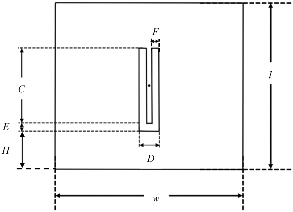
Figure 1: Configuration of the antenna
Next, U-slot is designed for high frequency band. The thickness of the slot (E) and (F) are determined by
where
The width
where
where the effective permittivity (
In this work, feeding point is considered at the patch center, which is symmetrically positioned along the E-plane. Therefore, the parameters of the antenna are adjusted to operate at frequencies of 0.7 and 2.6 GHz. The antenna configuration of the completed design using CST Microwave Studio is shown in Fig. 2. The antenna can operate in dual band frequencies, 0.7314 and 2.6892 GHz as shown in Fig. 3. The radiation pattern at frequency of 0.7 GHz is depicted in Fig. 4a while beam pattern at 2.6 GHz is interpreted in Fig. 4b.
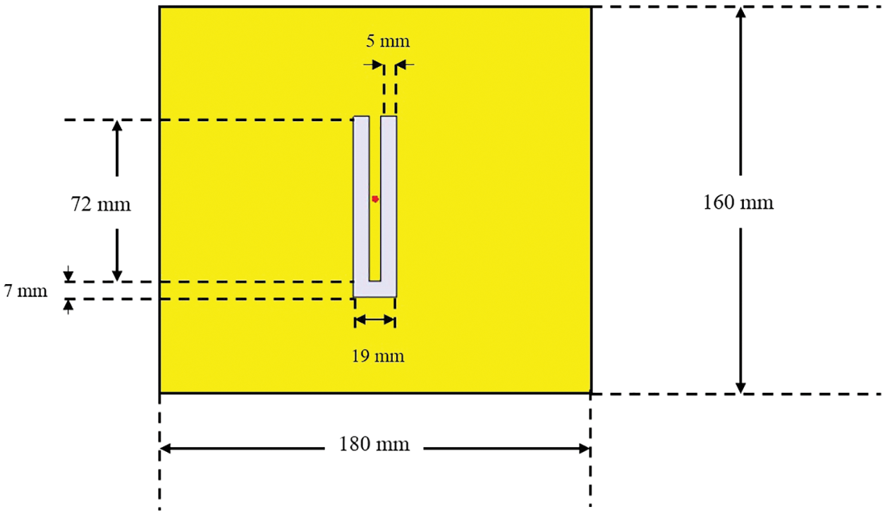
Figure 2: The structure of the antenna from simulation
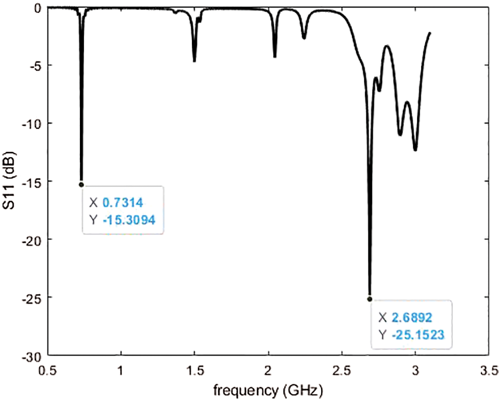
Figure 3: S11 of the antenna from simulation
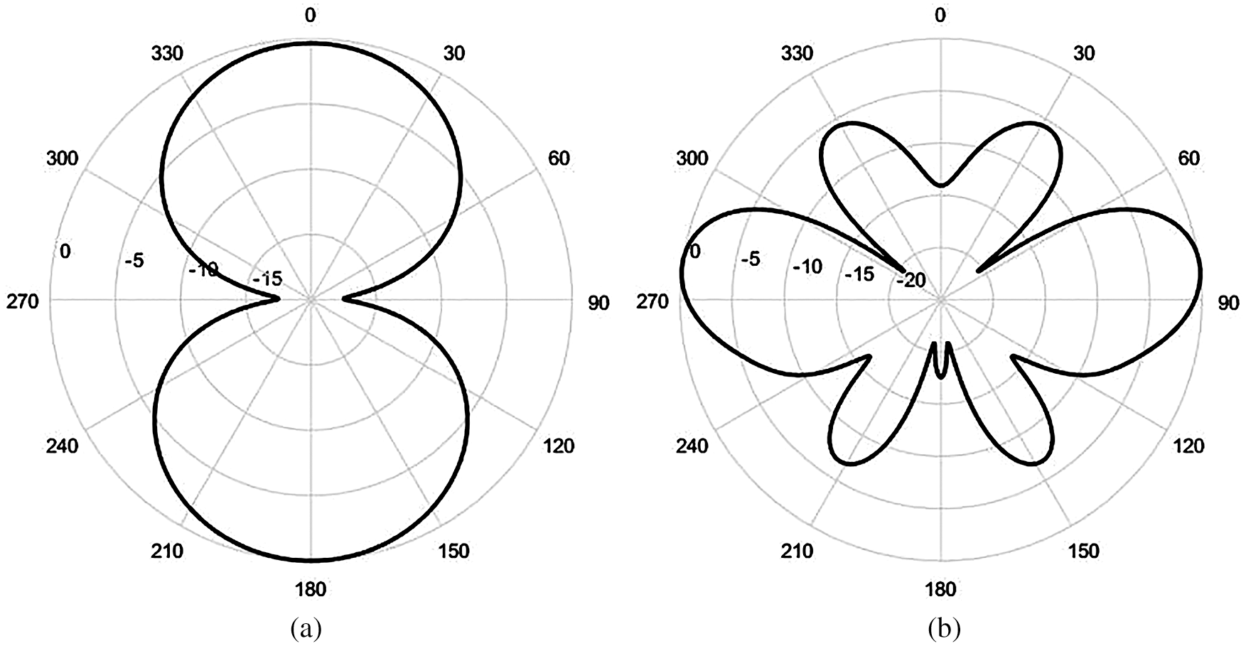
Figure 4: Radiation pattern of the antenna without shorted circuit at (a) 0.7 GHz and (b) 2.6 GHz
2.2 Switched Beam Antenna Design
In order to switch beam pattern, each edge of the antenna has a shorted circuit. There are two cases of shorted circuit, i.e. case A and case B as shown in Figs. 5a and 5b, respectively. In case A, corners A, which are the top-left and bottom-right of the antenna, are shorted circuit while corners B, the top-right and bottom-left, are shorted circuit as considered in case B. At the top of antenna, fifteen shorted positions of each edge are 2.5 mm apart which Fig. 6a is illustrated shorted positions of corner A, top-left of the patch are shorted circuit to beam steerable. At the bottom of antenna, nine shorted positions of each edge are 5 mm apart which Fig. 6b is illustrated shorted positions of corner A, bottom-right of the patch are shorted circuit to beam steerable. It should be noted that the number of short circuit points and spacing between each shorting point of top-antenna and bottom-antenna is not equal because the structure of the U-slot is not symmetrical. The result in term of S11 is shown in Fig. 7, which can confirm that the proposed switched beam antenna can operate in dual band frequencies. S11 of case A and case B have the same result due to the symmetry structure of the switched beam antenna. Moreover, radiation patterns in the E-plane of two cases are revealed in Figs. 8a and 8b at frequencies of 0.7 and 2.6 GHz, respectively. As can be seen, when the edges, which have a low current distribution of the antenna, are shorted circuit, the beam pattern is switched in different directions of shorted positions. In addition, radiation patterns of case A and case B are similar. This is because the configuration of the antenna is symmetrical. Therefore, beam pattern of the proposed antenna can be switched in two different directions. The directions of case A are 28°/218° at 0.7 GHz and 32°/227° at 2.6 GHz while the directions of case B are 160°/332° at 0.7 GHz and 145°/325° at 2.6 GHz.
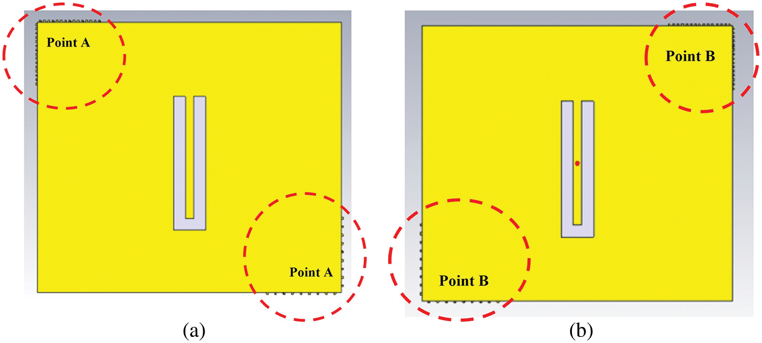
Figure 5: The switched beam antenna (a) case A and (b) case B
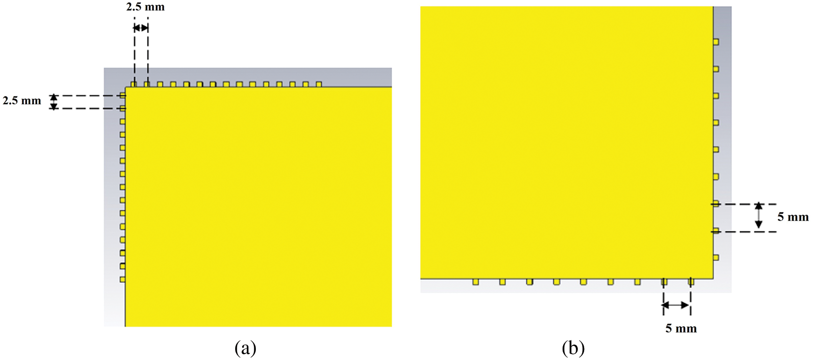
Figure 6: The shorted circuit positions of corner A at (a) top-left and (b) bottom-right
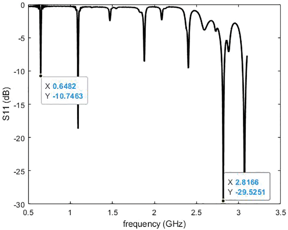
Figure 7: S11 of the switched beam antenna from simulation
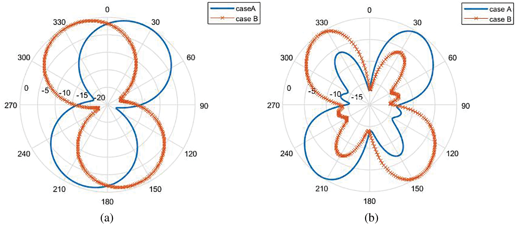
Figure 8: Radiation pattern of the switched beam antenna at (a) 0.7 GHz and (b) 2.6 GHz
In this section, the proposed antenna is constructed and tested to demonstrate its beam steering capability. The results in terms of S11 and radiation patterns of flat antennas are considered. Moreover, the bending effects on the performances of the antenna are studied.
The designed antenna is fabricated using foam fabric substrate with a dielectric constant of 1.52. Patch and ground are constructed from annealed copper as the structure shows in Fig. 9. The parameters of the designed and the fabricated antenna are shown in Tab. 1. The SMA connector is attached from one side through another side at the patch center. S11 and radiation patterns are measured using a network analyzer. S11 of the antenna without shorted circuit from measurement is shown in Fig. 10. It is −11.271 and −13.713 dB at 0.7 and 2.636 GHz, respectively. The radiation patterns are measured in anechoic chamber room as shown in Fig. 11 and the radiation patterns at 0.7 and 2.636 GHz are shown in Figs. 12a and 12b, respectively. Next, the antenna is shorted circuit to beam switching.
The structure of the shorting antenna at point B is shown in Fig. 13. S11 of the antenna with shorted circuit from measurement is shown in Fig. 14. It is −8.671 and −12.594 dB at 0.681 and 2.785 GHz, respectively. The radiation patterns at 0.681 GHz of case A and case B are shown in Fig. 15a. In addition, the radiation patterns at 2.785 GHz of case A and case B are shown in Fig. 15b. Main beam direction can be switched into two directions, about 30°/230° at 0.681 GHz, 45°/195° at 2.785 GHz in case A 140°/310° at 0.681 GHz and 115°/320° at 2.785 GHz in case B. As can be seen, the simulation results have a good agreement with the ones from the measurement. Moreover, S11 is moderately comparable and beam directions are relatively similar. Therefore, the proposed antenna can confirm its beam switching capability.
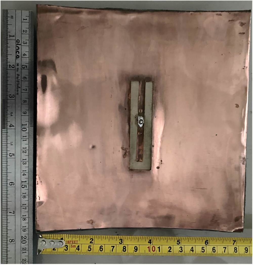
Figure 9: The fabricated antenna without shorted circuit

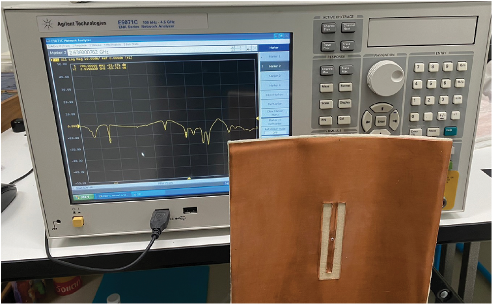
Figure 10: S11 of the fabricated antenna without shorted circuit
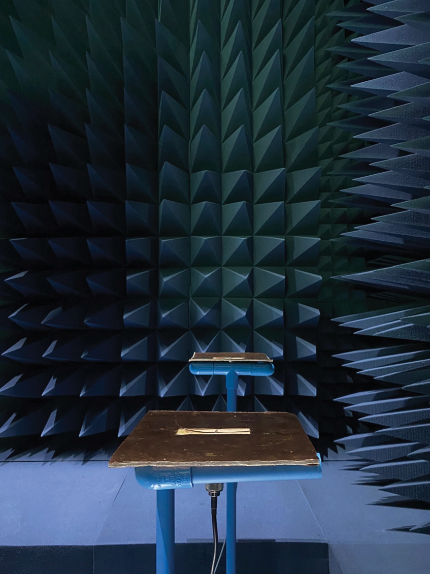
Figure 11: Radiation patterns measurement of flat antenna
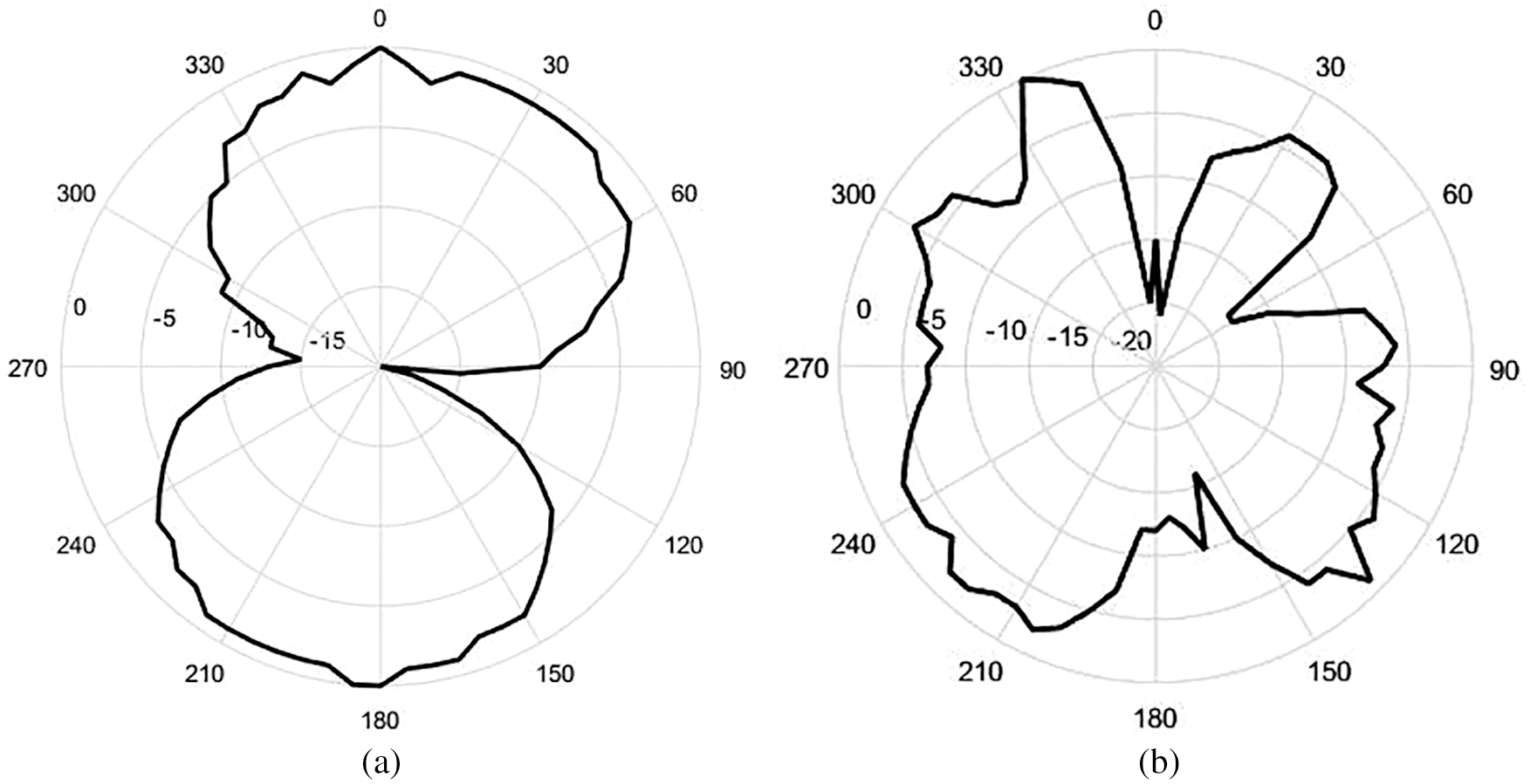
Figure 12: Radiation pattern of the fabricated antenna without shorted circuit at (a) 0.7 GHz and (b) 2.636 GHz
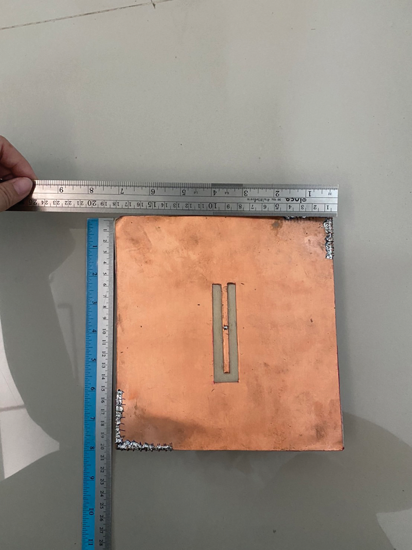
Figure 13: The fabricated antenna with shorted circuit at point B
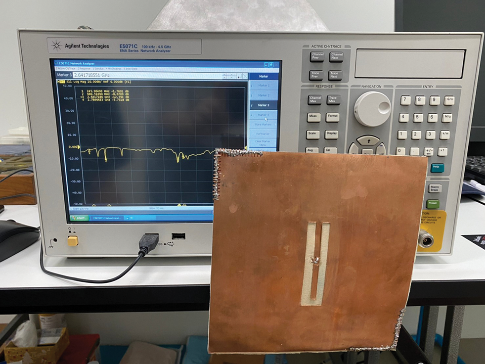
Figure 14: S11 of the fabricated antenna with shorted circuit
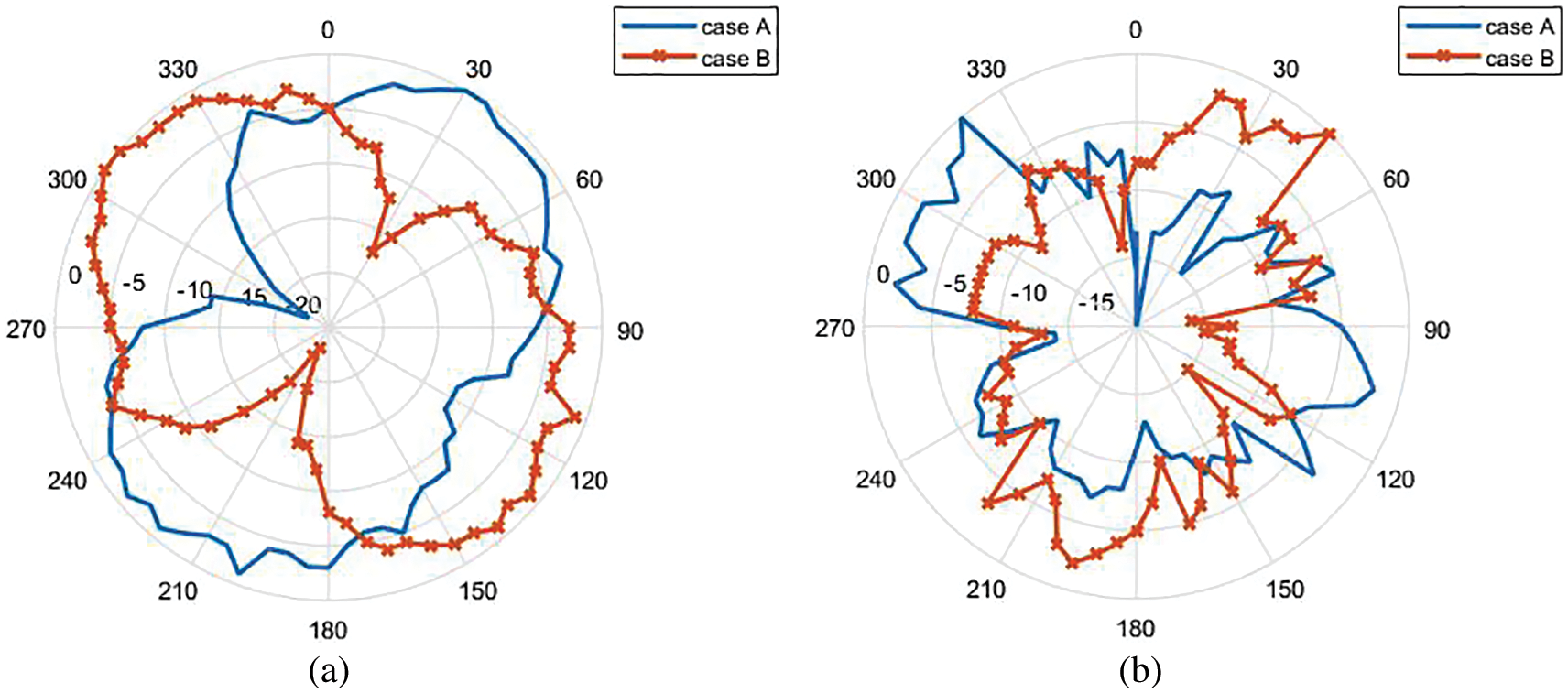
Figure 15: Radiation pattern of the fabricated antenna with shorted circuit at (a) 0.681 GHz and (b) 2.785 GHz
In this section, S11 and radiation patterns of the proposed antenna when it is bent in bending curvature radii of
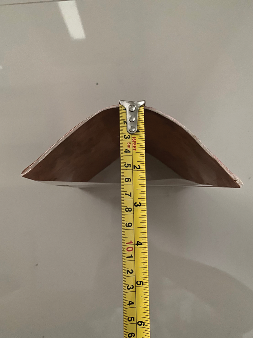
Figure 16: The bending antenna without shorted circuit
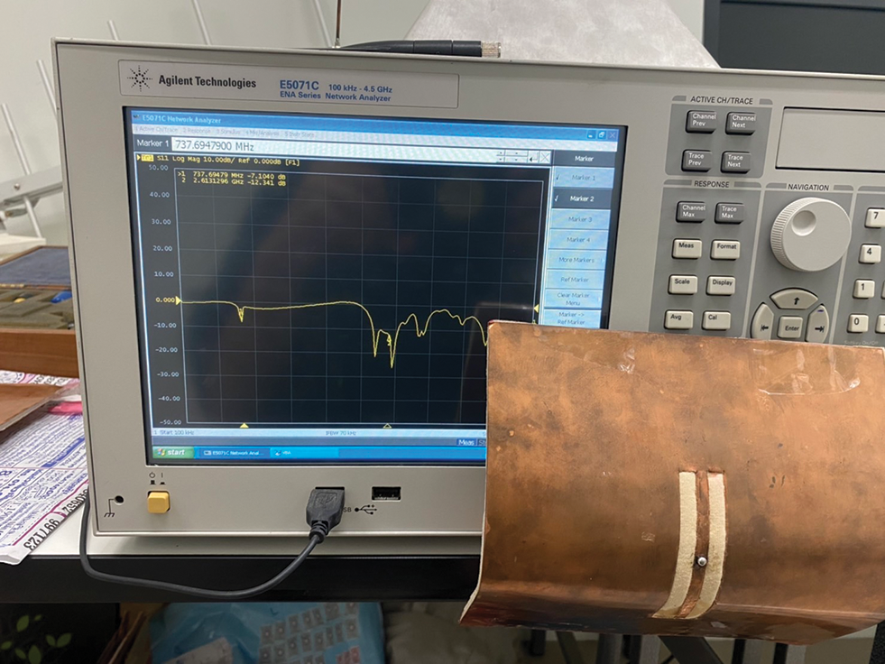
Figure 17: S11 of bending antenna without shorted circuit
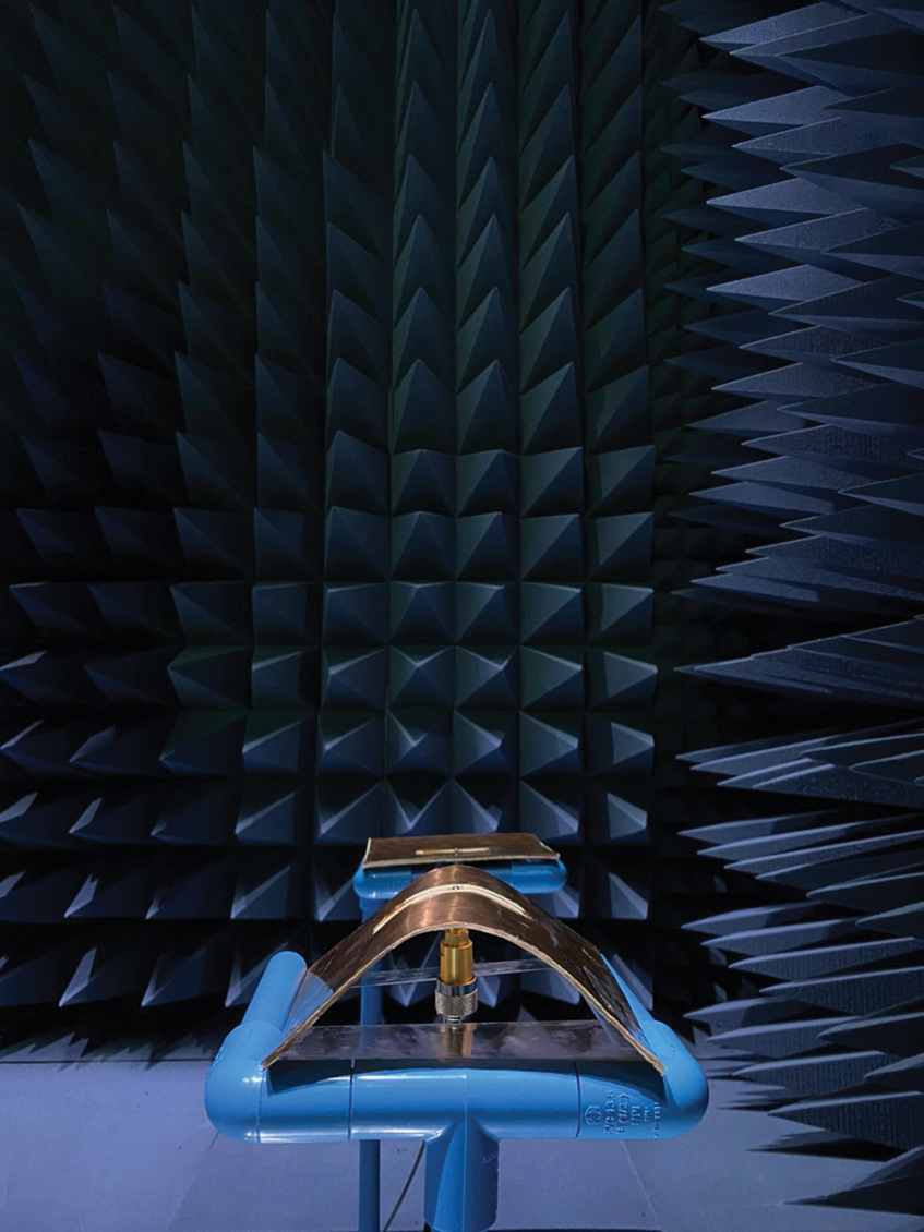
Figure 18: Radiation patterns measurement of bending antenna
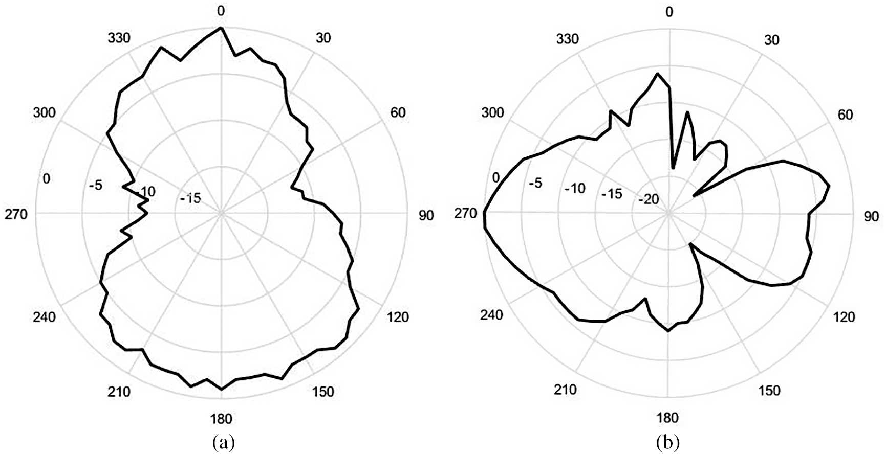
Figure 19: Radiation pattern of the bending antenna without shorted circuit at (a) 0.738 GHz and (b) 2.613 GHz
Next, the bending antenna with shorted circuit is considered as the structure with bending curvature radii of
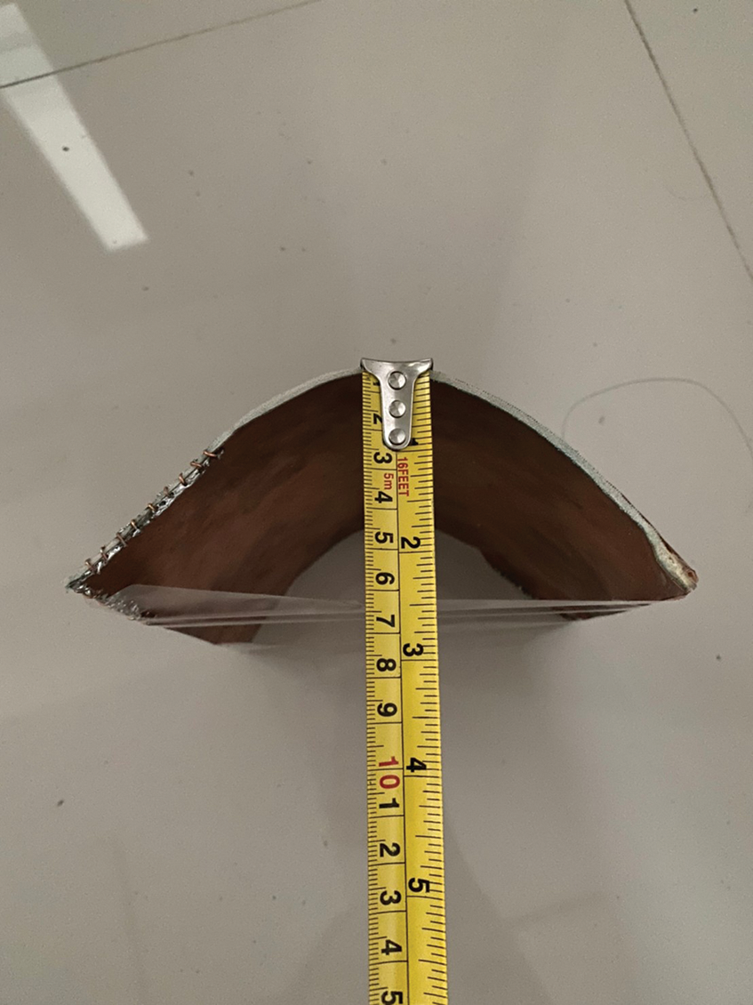
Figure 20: The bending antenna with shorted circuit at point A
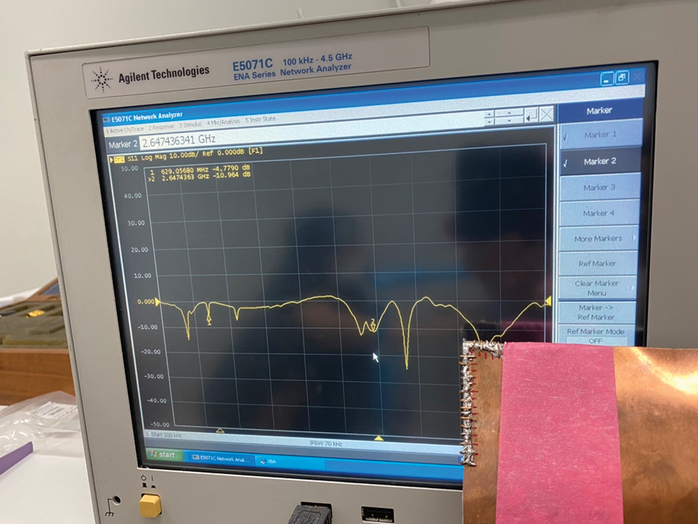
Figure 21: S11 of the bending antenna with shorted circuit
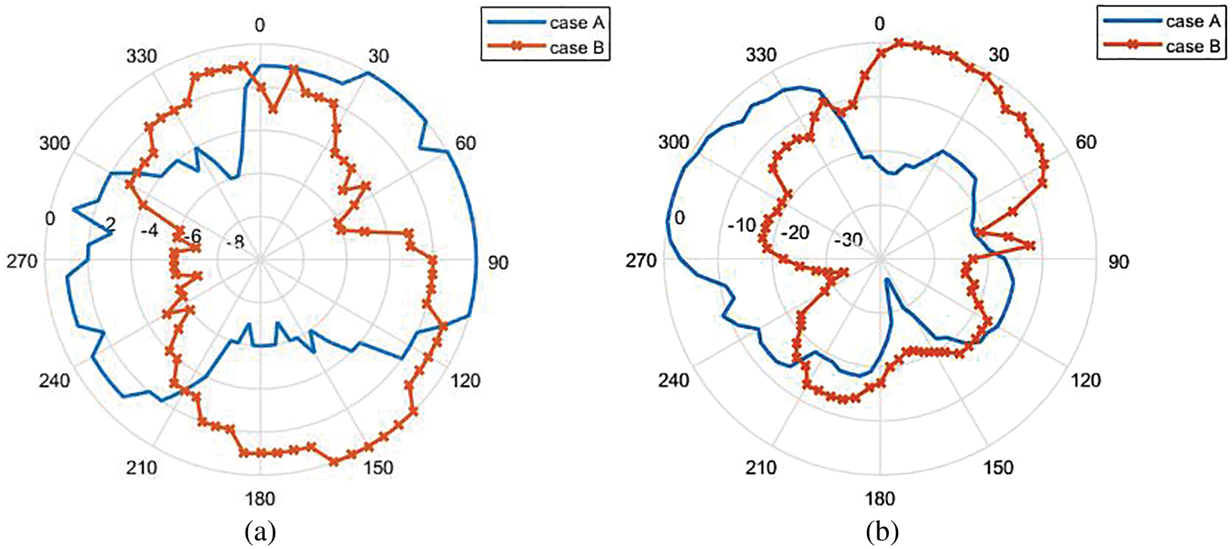
Figure 22: Radiation pattern of the bending antenna with shorted circuit at (a) 0.629 GHz and (b) 2.647 GHz
This paper has proposed a dual band switched beam antenna for 5G wireless communications. The antenna is designed and fabricated using foam fabric substrate, which is a flexible material. The antenna can operate dual frequency bands, about 0.7 and 2.6 GHz, and it is capable of beam switching for two different directions. Beam pattern can be switched by shorted circuits at edges of the patch (point A and point B). Its beam switching capability has been confirmed through simulation and measurement. Moreover, the antenna is bent with curvature radius of 6 mm in forward direction to study the effect in terms of S11 and radiation patterns. The advantages of the proposed antenna are that it has a simple structure, it is flexible, it is easy to perform beam switching, and it can operate dual band on only a single patch.
Acknowledgement: Financial support from the Thailand Science Research and Innovation through the research grant No. 036/2564 is acknowledged. Moreover, the authors acknowledge the support from Srinakharinwirot University, Thailand.
Funding Statement: This work is funded from the Thailand Science Research and Innovation through the research grant No. 036/2564, https://www.tsri.or.th/.
Conflicts of Interest: The authors declare that they have no conflicts of interest to report regarding the present study.
1. A. Denis, Overview of ITU-T Activities on 5G/IMT-2020. ITU Committed to Connecting the World, 2019. [Online]. Available at: https://www.itu.int. [Google Scholar]
2. B. Sanou, Setting the Scene for 5G: Opportunities & Challenges. 2018 International Telecommunication Union, 2018. [Online]. Available at: https://www.itu.int. [Google Scholar]
3. C. Lee, 5G Basics. 2017 International Telecommunication Union, 2017. [Online]. Available at: https://www.itu.int. [Google Scholar]
4. M. Carugi, Key Features and Requirements of 5G/IMT-2020 Networks. 2018 ITU Arab Forum on Emerging Technologies, 2018. [Online]. Available at: https://www.itu.int. [Google Scholar]
5. F. E. I. Khalifa, A. A. Ibrahim, M. Z. Ibrahim, M. M. Fathalrahman and M. A. Alhassan, “Design of dual-band microstrip antenna with U-shaped slot,” International Journal of Engineering Trends and Technology, vol. 55, no. 1, pp. 35–40, 2018. [Google Scholar]
6. P. Chaipanya, P. Rattanakriengkai, P. Potup. and L. Lapourailers, “A dual-band single-feed switched beam antenna for WLAN,” International Journal of Electronics and Telecommunications, vol. 63, no. 4, pp. 405–410, 2017. [Google Scholar]
7. H. F. Abutarboush, W. Li and A. Shamim, “Flexible-screen-printed antenna with enhanced bandwidth by employing defected ground structure,” IEEE Antennas and Wireless Propagation Letters, vol. 19, no. 10, pp. 1803–1807, 2020. [Google Scholar]
8. K. Thongda, T. Jangjing, P. Rakluea and B. Kumkhet, “Textile slot bow-tie antenna for wide band application,” in International Conference on Electrical Engineering/Electronics, Computer, Telecommunications and Information Technology (ECTI-CON), Chiang Mai, Thailand, pp. 197–200, 2021. [Google Scholar]
9. H. F. Abutarboush, “Silver nanoparticle inkjet-printed multiband antenna on synthetic paper material for flexible devices,” Alexandria Engineering Journal, vol. 61, no. 8, pp. 6349–6355, 2022. [Google Scholar]
10. P. Njogu, B. Sanz-Izquierdo, A. Elibiary, S. Y. Jun, Z. Chen et al., “3D printed fingernail antennas for 5G applications,” IEEE Access, vol. 8, pp. 228711–228719, 2020. [Google Scholar]
11. P. J. Soh, S. J. Boyes, G. Vandenbosch, Y. Huang and S. L. Ooi, “On-body characterization of dual-band all-textile PIFA,” Progress in Electromagnetics Research, vol. 129, pp. 517–539, 2012. [Google Scholar]
12. H. Yang and X. Liu, “Wearable dual-band and dual-polarized textile antenna for on- and off-body communications,” IEEE Antennas and Wireless Propagation Letters, vol. 19, no. 12, pp. 2324–2328, 2020. [Google Scholar]
13. M. I. Ahmed and M. F. Ahmed, “A wearable flexible antenna integrated on a smart watch for 5G applications,” Journal of Physics: Conference Series, vol. 1447, pp. 1–7, 2020. [Google Scholar]
14. S. M. Saeed, C. A. Balanis, C. R. Birtcher, A. C. Durgun and H. N. Shaman, “Wearable flexible reconfigurable antenna integrated with artificial magnetic conductor,” IEEE Antennas and Wireless Propagation Letters, vol. 16, pp. 2396–2399, 2017. [Google Scholar]
15. A. Ahmad, F. Arshad, S. I. Naqvi, Y. Amin, H. Tenhunen et al., “Flexible and compact spiral-shaped frequency reconfigurable antenna for wireless applications,” IETE Journal of Research, vol. 66, no. 1, pp. 22–29, 2020. [Google Scholar]
16. S. F. Jilani, Q. H. Abbasi and A. Alomainy, “Inkjet-printed millimetre-wave PET-based flexible antenna for 5G wireless applications,” in 2018 IEEE MTT-S Int. Microwave Workshop Series on 5G Hardware and System Technologies (IMWS-5G). Dublin, Ireland, 1–3, 2018. [Google Scholar]
17. S. Amendola, A. Palombi and G. Marrocco, “Inkjet printing of epidermal RFID antennas by self-sintering conductive ink,” IEEE Transactions on Microwave Theory and Techniques, vol. 66, no. 3, pp. 1561–1569, 2018. [Google Scholar]
18. S. G. Kirtania, A. W. Elger, Md. R. Hasan, A. Wisniewska, K. Sekhar et al., “Flexible antennas: A review,” Micromachines, vol. 11, pp. 1–43, 2020. [Google Scholar]
19. B. Mohamadzade, R. M. Hashmi, R. B. V. B. Simorangkir, R. Gharaei, S. U. Rehman et al., “Recent advances in fabrication methods for flexible antennas in wearable devices: State of the art,” Sensors, vol. 19, no. 10, pp. 1–21, 2019. [Google Scholar]
20. B. Gross Frank, “Smart antenna,” in Smart Antenna for Wireless Communications with MATLAB, 1st ed., McGraw-Hill, pp. 207–266, 2005. [Google Scholar]
21. A. E. Zooghby, “Fixed beam smart antenna systems and adaptive array systems,” in Smart Antenna Engineering, Norwood, USA: Artech House Publishers, pp. 83–158, 2005. [Google Scholar]
22. N. Seman, N. S. M. Suhaimi and T. H. Chua, “26 GHz phase shifters for multi-beam Nolen matrix towards fifth generation (5G) technology,” Bulletin of Electrical Engineering and Informatics, vol. 8, no. 3, pp. 1028–1035, 2019. [Google Scholar]
23. A. Kausar, H. Mehrpouyan, M. Sellathurai, R. Qian and S. Kausar, “Energy efficient switched parasitic array antenna for 5G networks and IoT,” in Loughborough Antennas & Propagation Conference (LAPC), Loughborough, UK, pp. 1–5, 2016. [Google Scholar]
24. T. Elhabbash and T. Skaik, “Design of dual-band dual-polarized MIMO antenna for mm-wave 5G base stations with octagonal prism structure,” in 2019 IEEE 7th Palestinian Int. Conf. on Electrical and Computer Engineering (PICECE), Gaza, Palestine, pp. 1–6, 2019. [Google Scholar]
25. P. Chaipanya, M. Punchin, N. Prasoptunya and W. Phothong-ngam, “Low cost multiband switched beam antenna for 5G applications,” in 2018 Int. Electrical Engineering Congress (iEECON), Krabi, Thailand, pp. 1–4, 2018. [Google Scholar]
26. M. I. Jais, M. F. Jamlos, M. Jusoh, T. Sabapathy, M. R. Kamarudin et al., “A novel 2.45 GHz switchable beam textile antenna (Sbta) for outdoor wireless body area network (WBAN) applications,” Progress In Electromagnetics Research, vol. 138, pp. 613–627, 2013. [Google Scholar]
27. A. Meredov, K. Klionovski and A. Shamim, “Screen-printed, flexible, parasitic beam-switching millimeter-wave antenna array for wearable applications,” IEEE Open Journal of Antennas and Propagation, vol. 1, pp. 2–10, 2020. [Google Scholar]
 | This work is licensed under a Creative Commons Attribution 4.0 International License, which permits unrestricted use, distribution, and reproduction in any medium, provided the original work is properly cited. |