DOI:10.32604/cmc.2022.028074
| Computers, Materials & Continua DOI:10.32604/cmc.2022.028074 | |
| Article |
Super Compact UWB Monopole Antenna for Small IoT Devices
1Department of Electronics and Computer Engineering (FKEKK), Center for Telecommunication Research and Innovation (CeTRI), Universiti Teknikal Malaysia Melaka (UTeM), Durian Tungal, 76100, Malaysia
2Department of Electrical and Electronics Engineering, Izmir Katip Celebi University, Izmir, 35620, Turkey
3Electrical Engineering Department, Jouf University, Sakaka, 72388, Aljouf, Kingdom of Saudi Arabia
4Universidad Carloa III de Madrid, Leganes, 28911, Madrid, Spain
5Space Science Centre, Climate Change Institute, Universiti Kebangsaan Malaysia (UKM), Bangi, 43600, Malaysia
*Corresponding Author: Zahriladha Zakaria. Email: zahriladha@utem.edu.my
Received: 01 February 2022; Accepted: 06 April 2022
Abstract: This article introduces a novel, ultrawideband (UWB) planar monopole antenna printed on Roger RT/5880 substrate in a compact size for small Internet of Things (IoT) applications. The total electrical dimensions of the proposed compact UWB antenna are 0.19 λo × 0.215 λo × 0.0196 λo with the overall physical sizes of 15 mm × 17 mm × 1.548 mm at the lower resonance frequency of 3.8 GHz. The planar monopole antenna is fed through the linearly tapered microstrip line on a partially structured ground plane to achieve optimum impedance matching for UWB operation. The proposed compact UWB antenna has an operation bandwidth of 9.53 GHz from 3.026 GHz up to 12.556 GHz at −10 dB return loss with a fractional bandwidth (FBW) of about 122%. The numerically computed and experimentally measured results agree well in between. A detailed time-domain analysis is additionally accomplished to verify the radiation efficiency of the proposed antenna design for the ultra-wideband signal propagation. The fabricated prototype of a compact UWB antenna exhibits an omnidirectional radiation pattern with the low peak measured gain required of 2.55 dBi at 10 GHz and promising radiation efficiency of 90%. The proposed compact planar antenna has technical potential to be utilized in UWB and IoT applications.
Keywords: Internet of things (IoT); ultra-wideband (UWB) application; compact UWB monopole antenna
Internet of Things (IoT) is a machine or asset with the intelligence behaviour used to communicate and update administration centre operations independently in real-time applications. The IoT applications require connectivity among the machines in many applications incorporating various transmission devices [1–4]. Aside from modern communication standards, the right selection of a radiating device is crucial for all these node ends of intelligent devices. To determine the most appropriate radiator for wireless applications is still a challenging technical task.
Federal Commission of Communication (FCC) approved a frequency band (3.1–10.6) GHz to be used without the requirement of any license [5]. UWB technology which has completed the standardization in a standoff in shooting industrial sectors. The UWB technology has gained considerable recognition across the last decade due to its large bandwidth, fast connectivity, saving power and low cost [6]. has therefore become technically beneficial for new application fields in wireless IoT connectivity [7,8]. It is the main reason why the extensive research activities in the UWB IoT antenna community are noticeable in the UWB society [9,10].
The fundamental antenna requirements for IoT UWB applications are: (1) compact overall physical size (miniaturisation), (2) wider operation bandwidth, and (3) technical ease of implementation and development with the electronic gadgets. Several literature studies have been discussed on IoT antenna miniaturisation due to the fact that antenna miniaturisation is a critical technical point of view within IoT devices in terms of integrability potential with the electronic circuits.
Several UWB IoT antenna configurations have been proposed in the scope of antenna miniaturisation [11–16]. A compact UWB antenna covering dual frequency bands from 1.0 to 3.65 GHz has been proposed for IoT applications systems in [11] with the antenna dimensions only about 25 mm × 35 mm × 1.6 mm. In [12], a wearable UWB IoT antenna operating in the frequency band from 4 GHz up to 6.2 GHz is printed on FR4 material with a total physical size of 31 mm × 41 mm × 1.6 mm. In [13], a UWB antenna operating in a wide range of frequencies from 3.04–10.70 GHz has been proposed for UWB and IoT systems. In [14], the authors have proposed a miniaturised antenna with a radiation efficiency of 60% in compact physical sizes of 25 mm × 40 mm × 1.6 mm for IoT applications. Rahman MuhibUr et al. have introduced a compact UWB antenna to be used for UWB and Bluetooth systems. The proposed antenna has a wide operation band covering the frequency ranges from 3.1 to 10.6 GHz and 2.4–2.484 GHz for Bluetooth application [15]. The last study in [16] has presented to be used for UWB IoT applications. The antenna was fabricated using Rogers/RT5880 and operated at various frequencies: 3.5, 4.5, 5.25, 5.7, and 8.2 GHz, respectively. A summary of the contribution to the body of knowledge of this paper is listed below:
a) A new shape of the UWB antenna was proposed (Modified rectangular patch monopole (MRPM) antenna.), and it obtained a pure bandwidth of 9.53 GHz ranging from 3.026 GHz up to 12.556 GHz with a high radiation efficiency of about 90%.
b) The novel UWB antenna model has a super compact size of 15 mm × 17 mm × 1.6 mm been extensively studied through comprehensive parametric analysis to achieve a final optimised antenna design for excellent impedance matching.
c) A detailed time-domain analysis is performed to demonstrate the radiation efficiency of the proposed antenna design for ultra-wideband and internet of things applications.
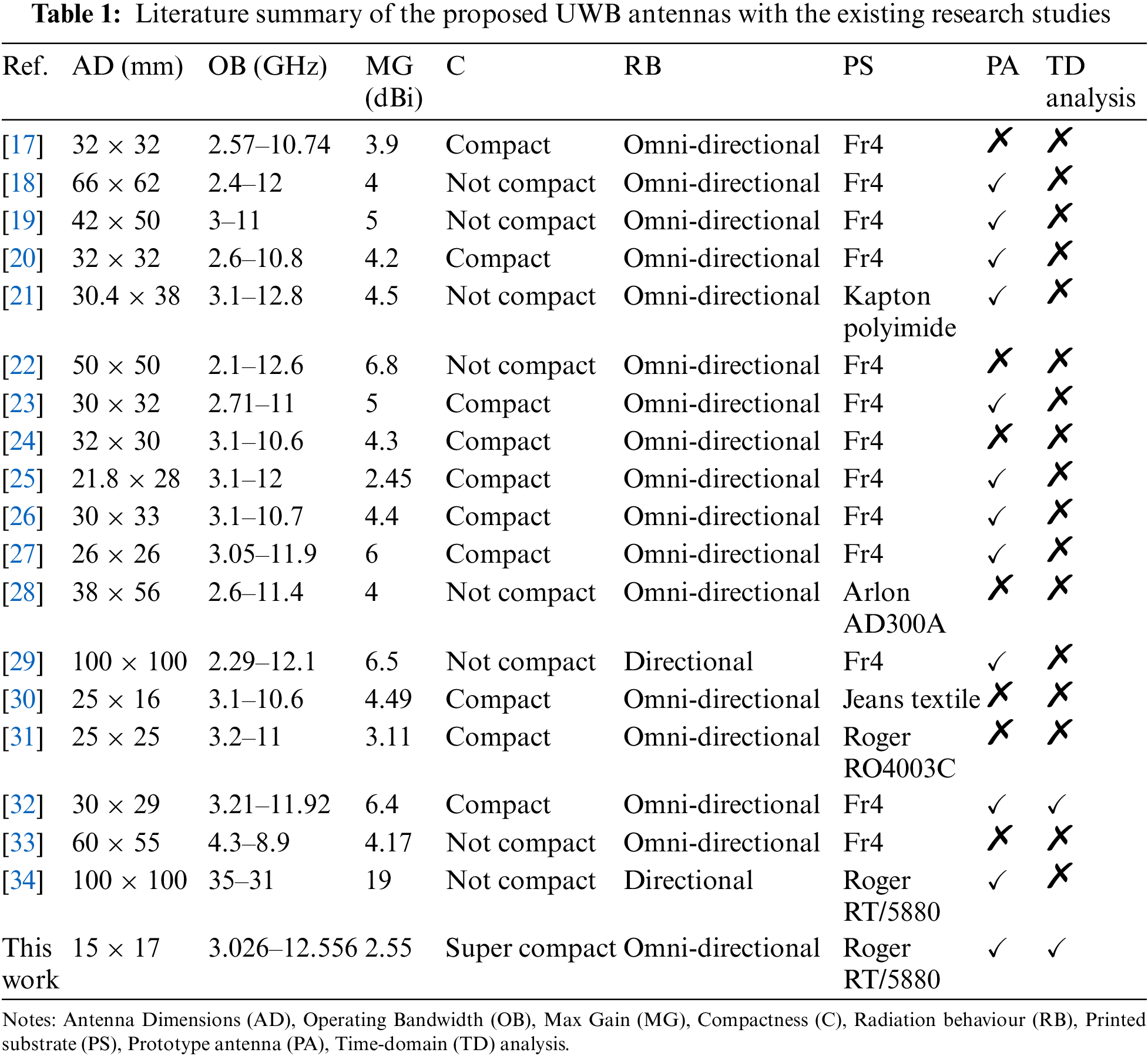
This paper introduces a super-compact miniaturised printed monopole antenna to be used for UWB and IoT applications. The overall electrical antenna size is 0.19 λo × 0.215 λo × 0.0196 λo with high radiation efficiency of about 90% for the operation bandwidth of 9.53 GHz ranging from 3.026 GHz up to 12.556 GHz. The novel UWB antenna model has been extensively studied through comprehensive parametric analysis to achieve a final optimised antenna design for excellent impedance matching. The compact UWB planar antenna model has been fabricated on a low dielectric loss Roger/RT 5880 laminate, which is well suited for high-frequency applications including UWB and IoT systems, for the simulating validations in time-domain analysis. A detailed RF performance comparison has been conducted in Tab. 1 to point out the superior performance of the proposed UWB compact antenna design in comparison to the various current UWB antenna configurations in terms of antenna dimensions, operating bandwidth, compactness, radiation behaviour, printed substrate, time-domain analysis and antenna gain which this type of antennas required low gain to be used for IoT applications.
2 Design Antenna Geometry and Parametric Sweep
The proposed radiating patch is modelled in a structural form based on the rectangular and circular shaped radiators combined together for the super-compact UWB antenna. The antenna feeding line is structured in a geometric configuration of a linearly tapered transmission line consisting of triangular outer surfaces of low line impedance and converging to a particular level of high line impedance in a gradual manner. The substrate material of compact UWB antenna is RT/5880 of Roger laminate of relative permittivity of 2.2 and a loss tangent of 0.0009 with the thickness of 1.54 mm. Fig. 1 presents the geometrical model of the final compact UWB planar monopole antenna.
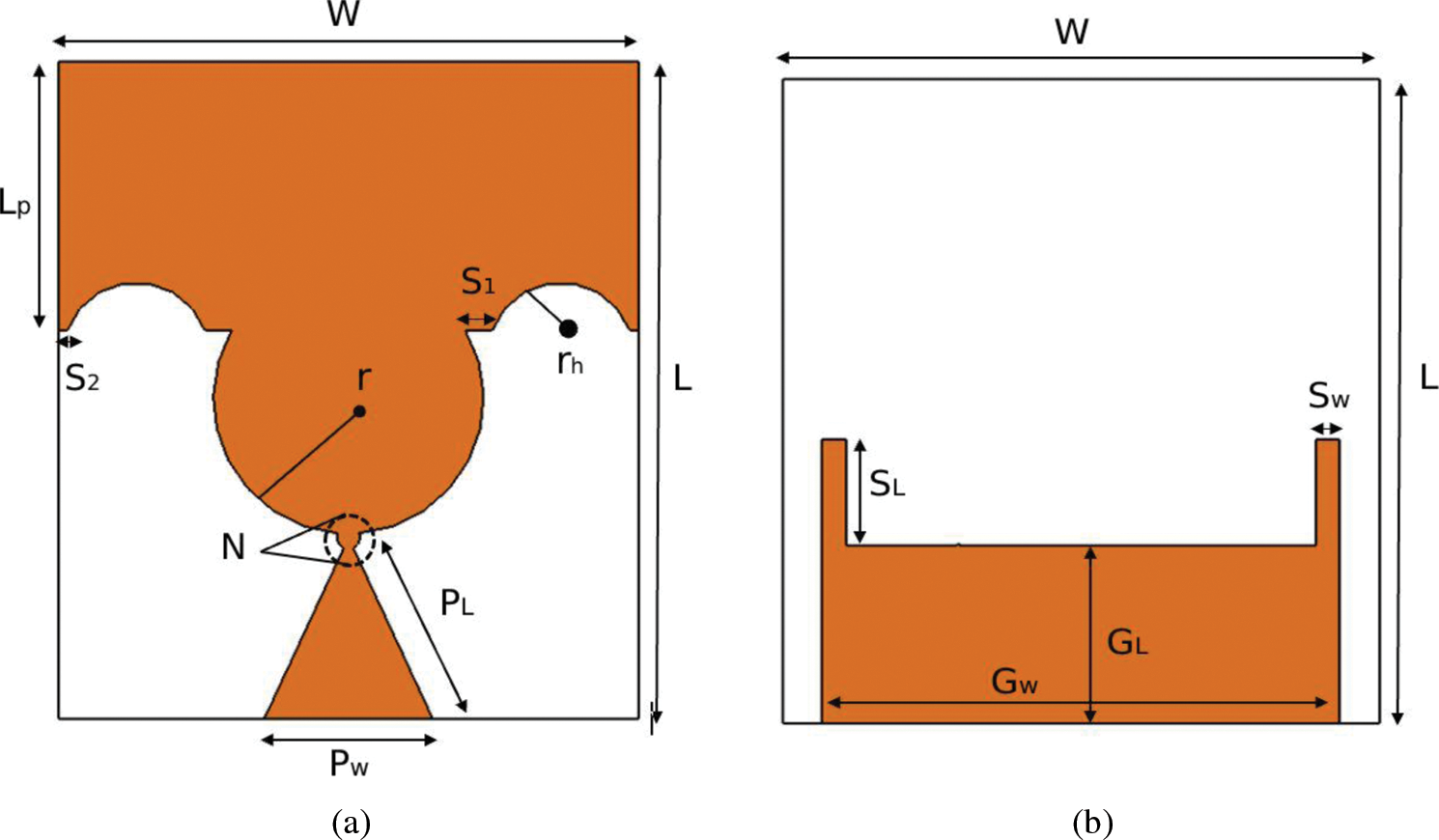
Figure 1: Antenna layout with its parameters. (a) Front look, (b) Back look
The fundamental modelling approach of the proposed antenna configuration is based on the structural combination of circular and rectangular shaped patches on partial ground plane. A rectangular patch size of L = 12 mm and W = 10 mm is considered at the first step of the design procedure with a circular patch radius of 4 mm.
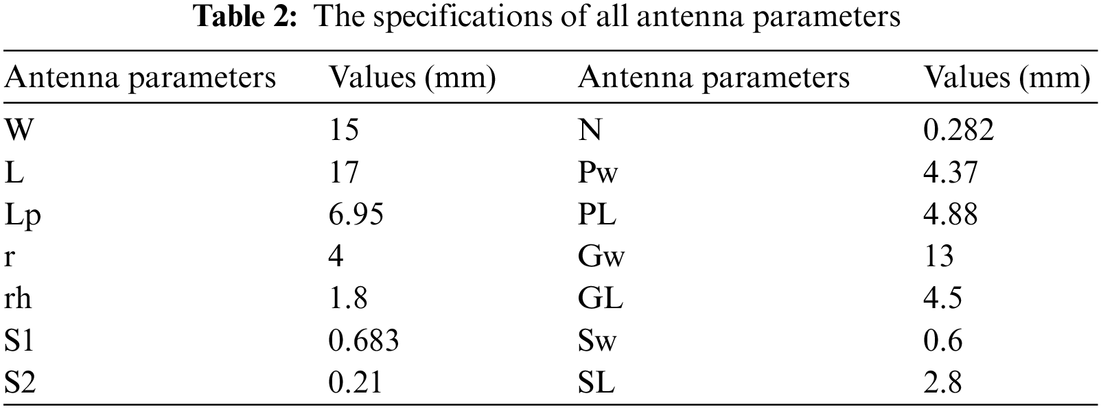
The final antenna model is numerically studied through a 3D electromagnetic field solver, CST Studio Suite. The optimum geometric parameters are listed in Tab. 2.
To validate the design procedure and achieve excellent impedance matching performance, three different design scenarios are numerically analyzed in terms of reflection coefficient (S11) performances, as shown in Fig. 2. From Fig. 2, the first design scenario is relying on the conventional circular monopole (CCM) antenna, whereas the second design scenario is based on the rectangular patch monopole (RPM) antenna. The final design scenario is the modified rectangular patch monopole (MRPM)antenna as shown in Fig. 2c.
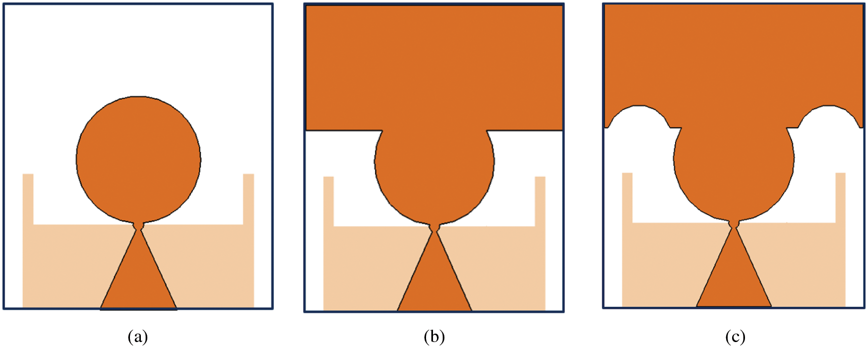
Figure 2: Development scenarios of the advanced planar monopole antenna: (a) Conventional circular monopole (CCM) antenna, (b) Rectangular patch monopole (RPM) antenna, and, (c) Modified rectangular patch monopole (MRPM) antenna
Scenario-1 (D1): The primary UWB compact antenna model in the first design scenario is starting from the conventional circular monopole (CCM) antenna as shown in Fig. 2a, which has been printed on Rogers/RT 5880 laminate with relative permittivity of 2.2 and a loss tangent of 0.0009. The CCM consists of a circular patch along with a linearly tapered microstrip feeding line, which are connected at the circular common node of radius 1.8 mm. The circular patch radius (r) is 3.5 mm, with the ground plane dimensions kept totally the same for all the design scenarios. The CCM antenna design has a narrow bandwidth of 2.126 GHz for the operation band ranging from 13.77 to 15.896 GHz, which does not incorporate the UWB frequencies as stated by the FCC, as shown in Fig. 3.
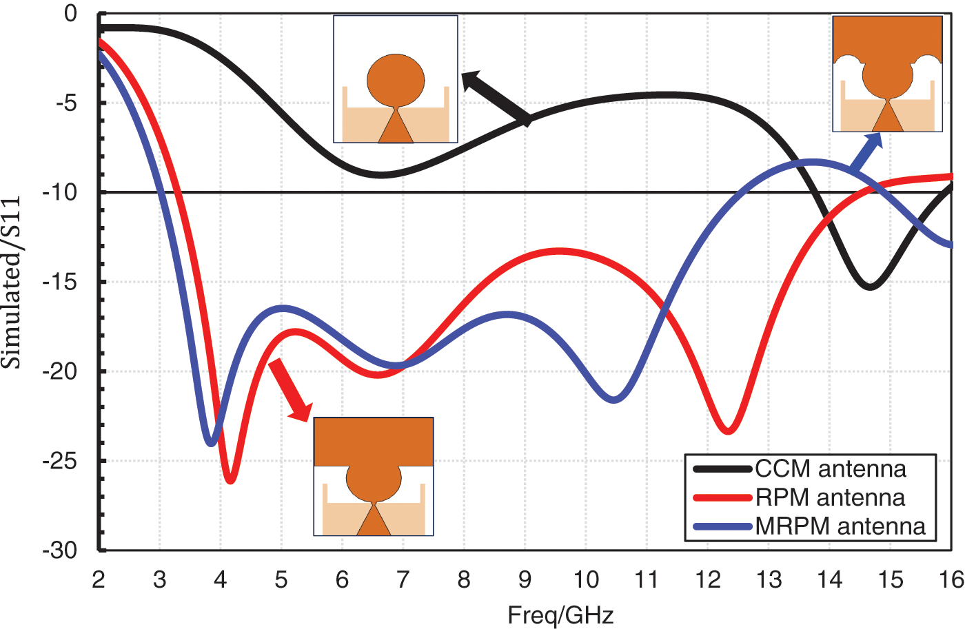
Figure 3: Simulated S11 of CCM antenna, RPM antenna and the modelled MRPM antenna
Scenario-2 (D2): In the second scenario, the conventional circular monopole (CCM) antenna has been modified with the introduction of a rectangular patch antenna to be located at the upper part of the circular patch to design the rectangular patch monopole (RPM) antenna as shown in Fig. 2b. The RPM antenna ground plane and feeding line dimensions are kept totally the same as presented in Scenario-1. The rectangular patch is added to the upper part of the circular patch to improve the antenna operation bandwidth. The RPM antenna is operated at a wide range of frequencies from 3.314 to 15.5 GHz with a frequency bandwidth of 12.186 GHz, as shown in Fig. 3. However, the RPM antenna has to be still developed to meet the technical specifications dictated by the FCC.
Scenario-3 (D3): The third scenario is the final antenna model to be proposed as the modified rectangular patch monopole (MRPM) antenna. The MRPM antenna ground plane and feeding line dimensions are kept the same as the previously presented antenna models in Scenario-1 and Scenario-2, respectively. The MRPM antenna has been designed through cutting the half circular-shaped patches at both sides of the rectangular patch, as shown in Fig. 2c. The circular-shaped parts to be removed from the rectangular patch lead to improve the antenna impedance matching. The MRPM antenna has exhibited an operation bandwidth of 9.53 GHz for the frequency band ranging from 3.026 to 12.556 GHz, as shown in Fig. 3. As deduced from Fig. 3, the S11 parameter is lower than −15 dB between 3.35 and 11.552 GHz, covering UWB frequency bandwidth better impedance matching performance.
In order to characterise UWB responses of the compact planar MRPM antenna, the surface current distributions at 3, 6, 9, and 12 GHz are shown in Fig. 4. As shown in Fig. 4a, the surface current is primarily concentrated on the linearly tapered feeding line with a high current value. At this resonant frequency of 3 GHz, it is noticed that the current is not followed at the upper patch of the radiating patch, which acts as a frequency function. Unlike at 6 GHz, which is the current concentrated equally, it means that the current is distributed both on the antenna patch and the pyramid feed line. It can be noted that the current follows more stable at 9 GHz. Lastly, at 12 GHz, the current distribution is decreased to achieve 151 A/m.
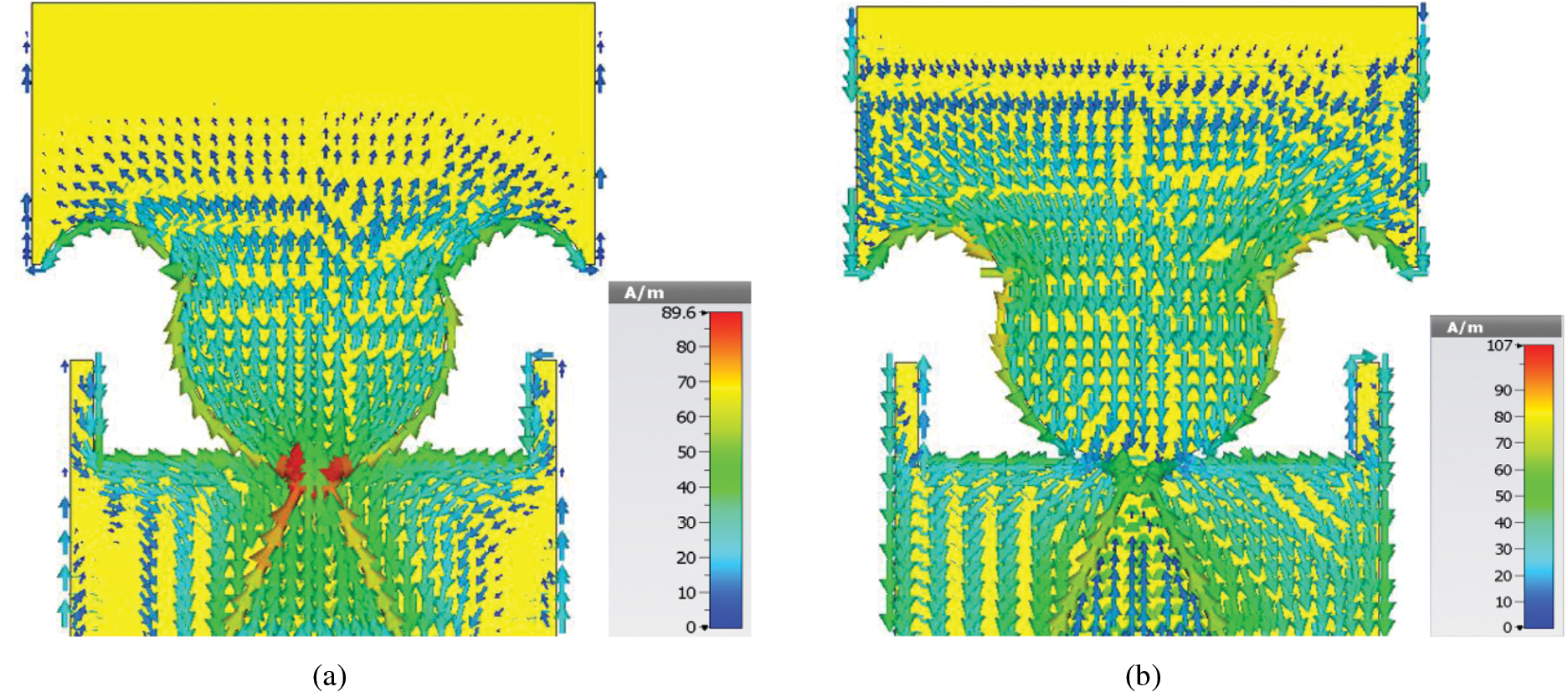
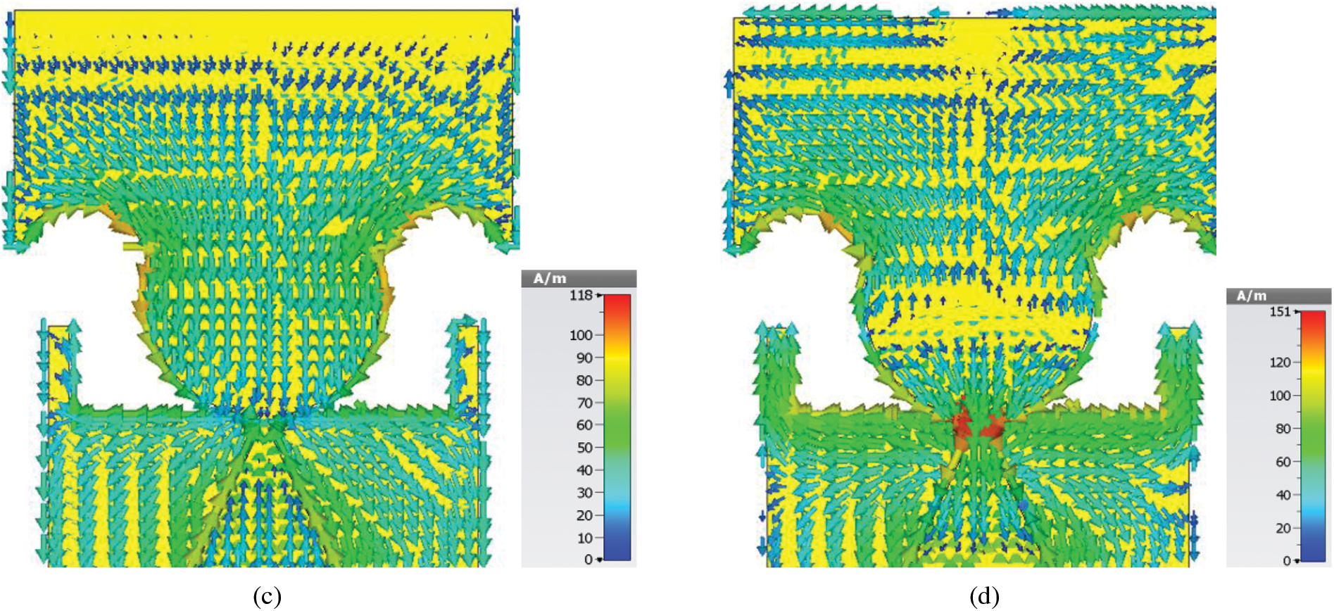
Figure 4: Current follows concentrations at several frequencies such as. (a) 3 GHz, (b) 6 GHz, (c) 9 GHz and, (d) 12 GHz
3 Simulation and Testing Outcomes
To confirm the legality of the intended design, a fabricated prototype of the stated antenna is manufactured and experimentally discussed. Based on geometrical studies suggested in Figs. 1 and 2c, a design geometry is taken (MRPM antenna), of this good reflection coefficient performance was fabricated. Fig. 5 displays the photographs of the fabricated antenna. It's worth mentioning that the proposed antenna is manufactured using RT/5880 of Roger laminate with a relative permittivity of 2.2 and a loss tangent of 0.0009. A microwave network analyser (ENA-series) model E5071C was used to perform the S11 up to 14 GHz for measurements setup. The measurement was held at Universiti Teknikal Malaysia Melaka (UTeM), Melaka, Malaysia.

Figure 5: Manufactured prototype. (a) Front look and, (b) Back look
The matching performance of the finalised UWB antenna was performed through S11. Fig. 6 presents the predicted and measured |S11| outcomes of the finalised antenna, which is considered multi resonance at various frequencies in the UWB range. Two simulated resonant frequencies appeared at different locations from the UWB ranges, and their resonant frequencies are 3. 836 and 9.866 GHz. Hence, their return loss performances are −19.297 and −31.3 dB respectively. The predicated results operated from 3.026 to 12.556 GHz with 9.53 GHz of net bandwidth and a fractional bandwidth (FBW) of 122%. Meanwhile, the measured outcomes offered an operational band from 3.1 to 12.4 and 9.3 GHz of pure bandwidth with FBW of 120%. These results confirmed that the antenna has a good agreement between the CST simulated results and the experimental one. However, there is a slight difference between the simulated and measured outcomes. This is because of fabrication inaccuracies due to the manual cutting of the textile materials and the variation of its dielectric constant [35]. In practice, the differences between simulations and measurements are also affected by the SMA connector losses, as an ideal connector is modelled in simulations. Besides that, the amount of power fed into the antenna in measurements is also affected by how the epoxy is applied to galvanically connect between the SMA connector and the used substrate material [36].

Figure 6: Predicated and measured |S11| for UWB MRPM antenna
The proposed UWB MRPM antenna radiation pattern is experimentally made in a non-resonant room by supplying some energy to the antenna, which is supplies room and estimating the power of the transmitted electromagnetic field (EM) in the encompassing place. An excellent antenna, in common, reflects 50%–60% of the force-fed to it (−3 dB to −2.2 dB). Fig. 7 shows the antenna's radiation pattern in the laboratory when positioned in both H-field and E-field.

Figure 7: Fabricated prototype in anechoic chamber positioned in. (a) H-field and, (b) E-field
The antenna radiation properties over the entire UWB operational band were measured and investigated. Fig. 8 displays both the predicated and measured H and E-field patterns at frequencies 3, 6, 9 and 12 GHz, as illustrated in Fig. 8, sequentially. The measured H-field far-field patterns are very close to those achieved in the CST [37–39]. It can be remarked that the H-field patterns are bi-directional at all frequencies of interest. The measured E-field patterns match the predicted patterns, though the agreement is less than the H-field patterns. There are some changes, ripples, and perversions on the experimental curves, which the SMA feed connector and the coaxial cable may be made.
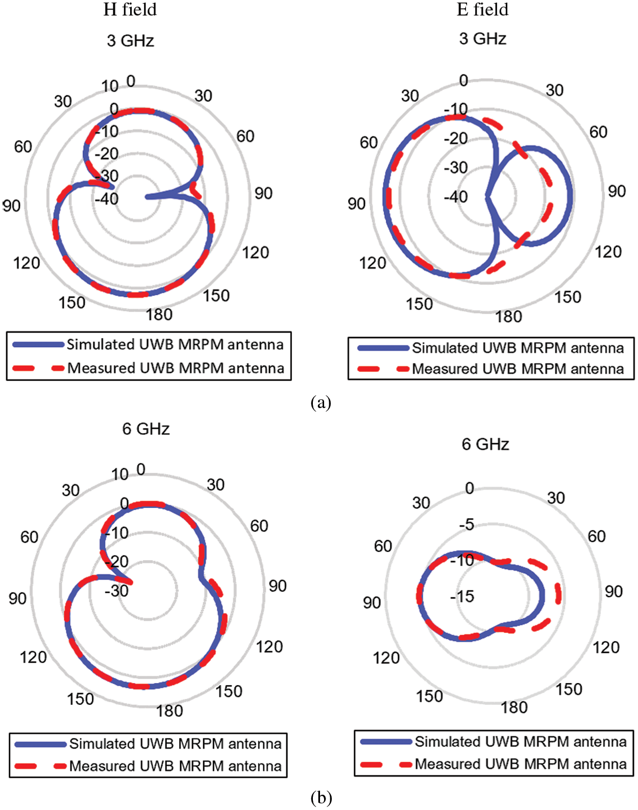
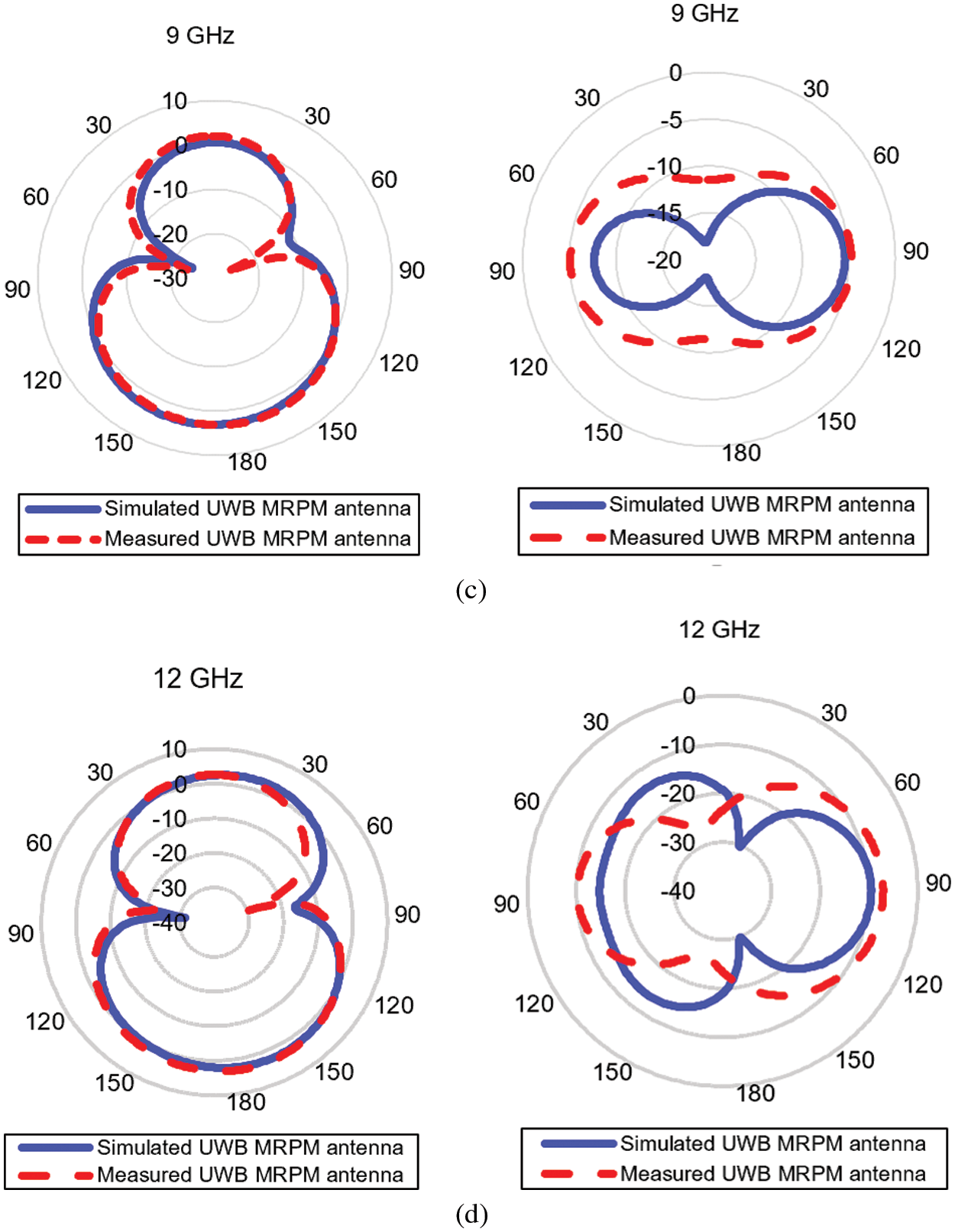
Figure 8: Predicated and measured H and E far-field patterns at. (a) 3 GHz, (b) 6 GHz, (c) 9 GHz and, (d) 12 GHz
The simulated and measured IEEE gain over frequency of the recommended MRPM antenna is displayed in Fig. 9a. Fig. 9a shows that the predicated MRPM antenna max gain is about 2.6 dBi over a high-frequency range at 10 GHz, while the max measured gain at the same frequency, which is 10 GHz is 2.55 dBi; we can conclude that there is an excellent agreement between the predicted and experimented outcomes. However, we noticed a remarkable phenomenon: The gain is relatively poor at a lower frequency due to the proposed antenna being super compact. In addition, there is an important question the came to our mind why the gain is down at the lower frequency, unlike those for the highest frequency. The answer is that when an antenna starts to radiate, the amount of power is not the same at all of the ultrawideband frequencies, meaning that the energy will spread unequally to all frequencies. The simulated and measured radiation efficiency (RE) of the proposed UWB MRPM antenna is presented in Fig. 9b. It exhibits that the recommended antenna provided a simulated radiation efficiency of 90% at 12 GHz, while the measured radiation efficiency is about at the same frequency is also 90%. As a result, the stated antenna has a very close agreement regarding the simulation and experimental rendition efficiency.

Figure 9: Simulated and measured outcomes of the MRPM antenna for, (a) IEEE gain (dB) and, (b) Radiation efficiency (%)
A time-domain analysis is introduced to validate the applicability of the modelled antenna in communication systems. Implementation in time domain is estimated utilising group delay operation and phase of transmission coefficient (S21). To determine the characteristics of the proposed antenna in time domain, two identical antenna designs are considered. Two similar UWB antennas with the same properties are regarded as transmitting antennas, and the other is considered a receiving antenna employed to investigate the complete system. In order to explore the system time domain routine, two different setups of the antenna are discussed. The first setup is to place the identical antennas side-by-side, and the other is face-to-face, as illustrated in Fig. 10. Both antennas are identified and separated by a distance of 100 mm in their line of sight.
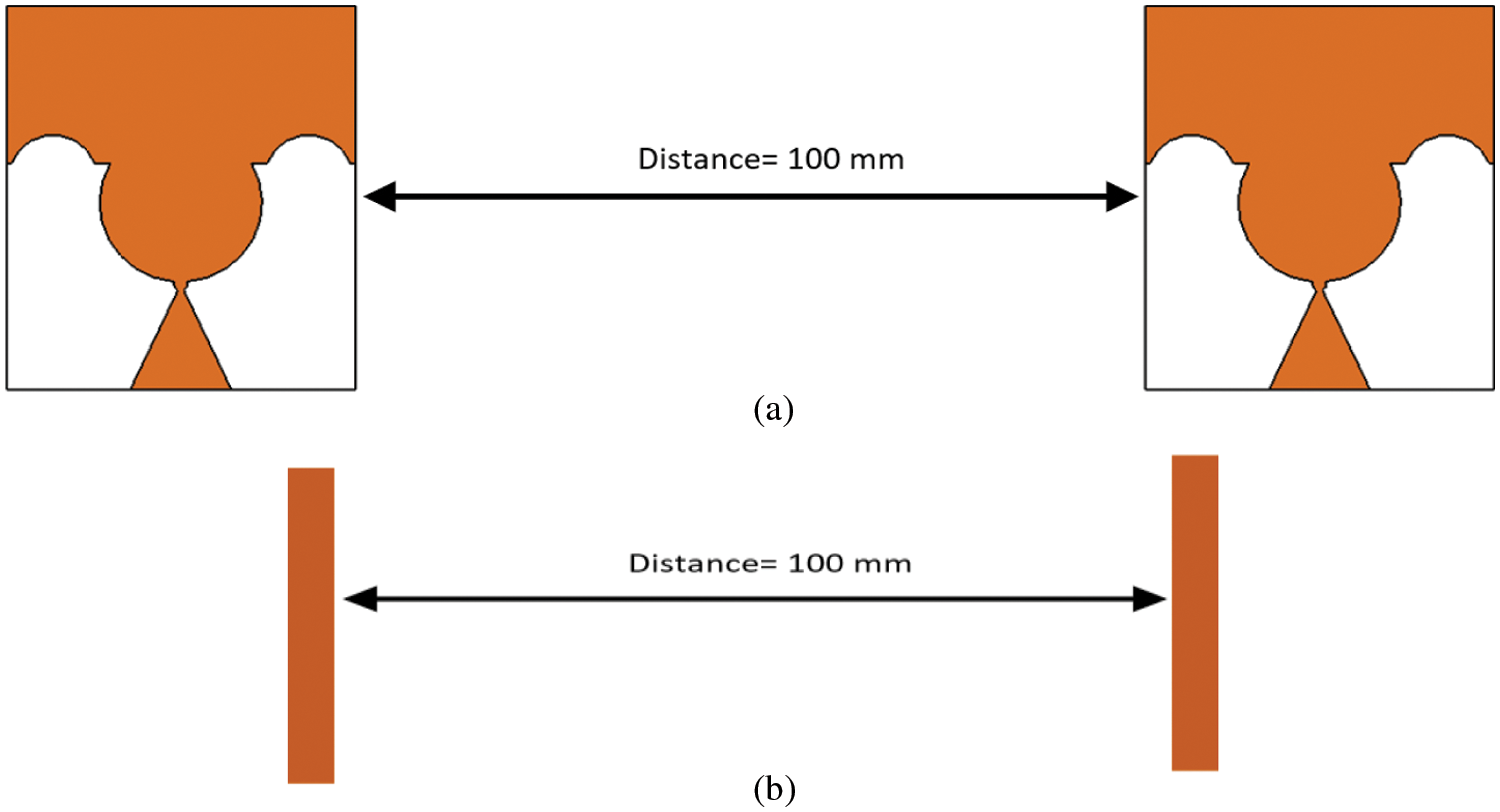
Figure 10: Two identical UWB antennas positioned. (a) Side-By-Side, and (b) Face-To-Face
The group delay is an important parameter to demonstrate the linear response of a communication platform. As shown in Fig. 11, the group delay variation for the proposed UWB antenna design is within the acceptable magnitude of 1.5 ns for both cases (Face-To-Face, Side-By-Side). The group delay of less than 1 ns exhibits a nonlinear phase response. The S21 phase for both cases is presented in Fig. 12. Based on the observations, for a perfect transmission, the group delay should be close to steady through the whole band. We can conclude that the proposed UWB antenna has ideal performance in this aspect, which makes it a good candidate for UWB and other higher band wireless communication.

Figure 11: Group delay of the finalized antenna for both Face-To-Face and Side-By-Side cases
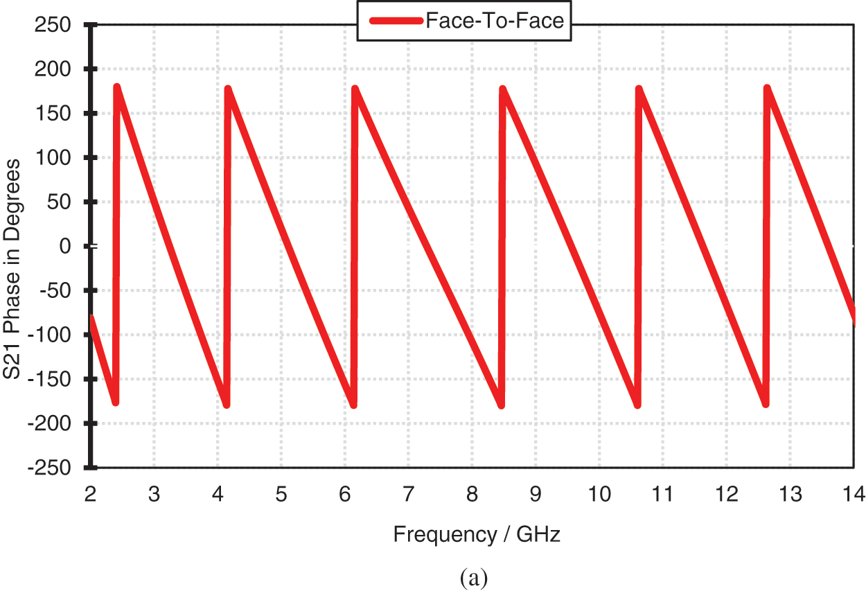
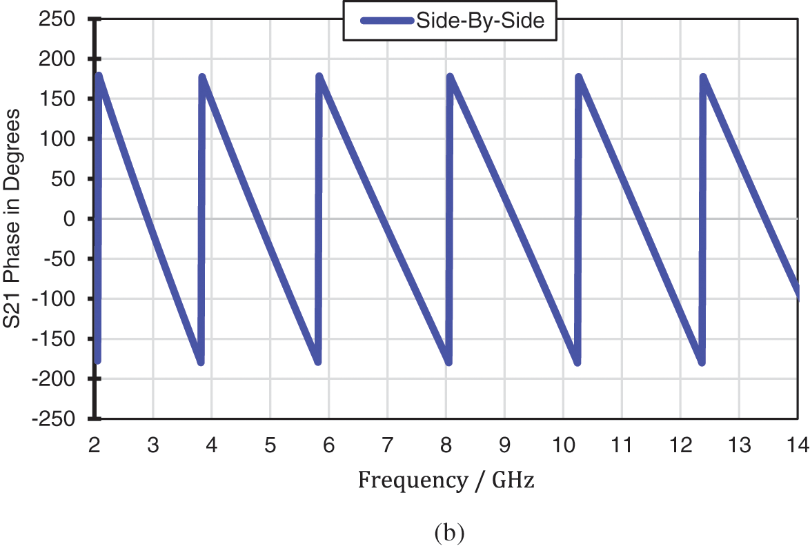
Figure 12: Transmission coefficient (S21) phase of the finalised antenna for both cases: (a) Face-To-Face and, (b) Side-By-Side
This study suggests and tests a new design and super compact UWB monopole antenna for conventional UWB properties. The total physical dimension of the modelled antenna is only 15 mm × 17 mm × 1.548 mm, while the antenna electrical dimensions are 0.19 λo × 0.215 λo × 0.0196 λo. The measured return loss of UWB antenna offered bandwidth of 9.3 GHz from 3.1 to 12.4 GHz covering the licences FCC spectrum for UWB applications, with FBW of 120%. The time-domain study was proposed for both the cases, i.e., face-to-face and side-by-side, exhibits outstanding performance in the open domain communication, with relatively good and consistent monopole such as omnidirectional radiation patterns in E and H-plane with linear transmission propagation. The finalised antenna contributes bi-direction radiation over the UWB spectrum with an acceptable measured gain of 2.55 dBi at 10 GHz. The UWB MRPM antenna granted a measured radiation efficiency of 90% at 12 GHz. Besides, the simulation results indicated an excellent agreement between the predicted and the experimental one, which makes this antenna a perfect choice for UWB and IoT applications.
Funding Statement: This work was supported by Universiti Teknikal Malaysia Melaka (UTeM) under Jurnal/2020/FKEKK/Q00053.
Conflicts of Interest: The authors declare that they have no conflicts of interest to report regarding the present study.
1. S. G. Kirtania, M. A. Riheen, S. U. Kim, K. Sekhar, A. Wisniewska et al., “Inkjet printing on a new flexible ceramic substrate for internet of things (IoT) applications,” Micromachines, vol. 11, no. 9, pp. 841, 2020. [Google Scholar]
2. O. Cetinkaya and O. B. Akan, “Electric-field energy harvesting from lighting elements for battery-less internet of things,” IEEE Access, vol. 5, no. 4, pp. 7423–7434, 2017. [Google Scholar]
3. A. Bekasiewicz and S. Koziel, “Compact UWB monopole antenna for internet of things applications,” Electronics Letters, vol. 52, no. 7, pp. 492–494, 2016. [Google Scholar]
4. A. J. A. Al-Gburi, I. B. M. Ibrahim, Z. Zakaria and N. F. B. M. Nazli, “Wideband microstrip patch antenna for sub 6 GHz and 5G applications,” Przegląd Elektrotechniczny, vol. 2021, no. 11, pp. 26–29, 2021. [Google Scholar]
5. First Report and Order, “Revision of part 15 of the commission’s rules regarding ultra-wideband transmission systems,” FCC 02-48, February 2002. [Google Scholar]
6. A. J. A. Al-Gburi, I. Ibrahim, Z. Zakaria, M. K. Abdulhameed and T. Saeidi, “Enhancing gain for UWB antennas using FSS: A systematic review,” Mathematics, vol. 9, no. 24, pp. 3301, 2021. [Google Scholar]
7. S. Ugwuanyi, G. Paul and J. Irvine, “Survey of IoT for developing countries: Performance analysis of LoRaWAN and cellular NB-IOT networks,” Electronics, vol. 10, no. 18, pp. 2224, 2021. [Google Scholar]
8. L. Davoli, L. Belli, A. Cilfone and G. Ferrari, “From micro to macro IoT: Challenges and solutions in the integration of IEEE 802.15.4/802.11 and Sub-GHz technologies,” IEEE Internet of Things Journal, vol. 5, no. 2, pp. 784–793, 2018. [Google Scholar]
9. S. Sharma, A. Gupta and V. Bhatia, “A simple modified peak detection based UWB receiver for WSN and IoT applications,” in IEEE Vehicular Technology Conf., Sydney, NSW, Australia, pp. 1–6, 2017. [Google Scholar]
10. A. J. A. Al-Gburi, I. M. Ibrahim and Z. Zakaria, “An ultra-miniaturized MCPM antenna for ultra-wideband applications,” Journal of Nano-and Electronic Physics, vol. 13, no. 5, pp. 05012-1–05012-4, 2021. [Google Scholar]
11. Q. Awais, H. T. Chattha, M. Jamil, Y. Jin and F. A. Tahir, “A novel dual ultrawideband CPW-fed printed antenna for internet of things (IoT) applications,” Wireless Communications and Mobile Computing, vol. 2018, no. 3, pp. 2179571–2179579, 2018. [Google Scholar]
12. M. Mustaqim, B. A. Khawaja, H. T. Chattha, K. Shafique and M. J. Zafar, “Ultra wideband antenna for wearable internet of things devices and wireless body area network applications,” International Journal of Numerical Modelling: Electronic Networks, Devices and Fields, vol. 32, no. 6, pp. 1–12, 2019. [Google Scholar]
13. S. G. Kirtania, B. A. Younes, A. R. Hossain, T. Karacolak and P. K. Sekhar, “CPW-fed flexible ultra-wideband antenna for IOT applications,” Micromachines, vol. 12, no. 4, pp. 453, 2021. [Google Scholar]
14. L. Lizzi, F. Ferrero, P. Monin, C. Danchesi and S. Boudaud, “Design of miniature antennas for IoT applications,” in 2016 IEEE 6th Int. Conf. on Communications and Electronics, Ha-Long, Vietnam, pp. 234–237, 2016. [Google Scholar]
15. M. U. Rahman, M. NagshvarianJahromi, S. S. Mirjavadi and A. M. Hamouda, “Compact UWB band-notched antenna with integrated bluetooth for personal wireless communication and UWB applications,” Electronics, vol. 8, no. 2, pp. 158, 2019. [Google Scholar]
16. M. U. Rahman and J. D. Park, “The smallest form factor UWB antenna with quintuple rejection bands for IoT applications utilizing RSRR and RCSRR,” Sensors (Switzerland), vol. 18, no. 3, pp. 911, 2018. [Google Scholar]
17. I. M. Ibrahim, A. J. A. Al-Gburi, Z. Zakaria and H. A. Bakar, “Parametric study of modified U shaped split ring resonator structure dimension at ultra-wide-band monopole antenna,” Journal of Telecommunication, Electronic and Computer Engineering, vol. 10, no. 2–5, pp. 53–57, 2018. [Google Scholar]
18. K. P. Ray and S. S. Thakur, “Modified trident UWB printed monopole antenna,” Wireless Personal Communications, vol. 109, no. 12, pp. 1689–1697, 2019. [Google Scholar]
19. H. A. Mohamed, A. S. Elkorany, S. A. Saad and D. A. Saleeb, “New simple flower shaped reconfigurable band-notched UWB antenna using single varactor diode,” Progress in Electromagnetics Research C, vol. 76, no. 8, pp. 197–206, 2017. [Google Scholar]
20. A. J. A. Al-Gburi, I. M. Ibrahim and Z. Zakaria, “Band-notch effect of U-shaped split ring resonator structure at ultra wideband monopole antenna,” International Journal of Applied Engineering Research, vol. 12, no. 15, pp. 4782–4789, 2017. [Google Scholar]
21. Y. Zhang, S. Li, Z.-Q. Yang, X.-Y. Qu and W.-H. Zong, “A coplanar waveguide-fed flexible antenna for ultra-wideband applications,” International Journal of RF and Microwave Computer-Aided Engineering, vol. 30, no. 3, pp. 1–11, 2020. [Google Scholar]
22. A. J. A. Al-Gburi, I. M. Ibrahim, Z. Zakaria, M. Y. Zeain, H. Alwareth et al., “High Gain of UWB CPW-fed mercedes-shaped printed monopole antennas for UWB applications,” Przegląd Elektrotechniczny, vol. 2021, no. 5, pp. 70–73, 2021. [Google Scholar]
23. S. C. Puri, S. Dasand and M. G. Tiary, “UWB monopole antenna with dual-band-notched characteristics,” Microwave and Optical Technology Letters, vol. 62, no. 3, pp. 1222–1229, 2020. [Google Scholar]
24. A. J. A. Al-gburi, I. M. Ibrahim and Z. Zakaria, “Gain enhancement for whole ultra-wideband frequencies of a microstrip patch antenna,” Journal of Computational and Theoretical Nanoscience, vol. 17, no. 2–3, pp. 1469–1473, 2020. [Google Scholar]
25. A. S. Al-Zayed and V. A. Shameena, “A novel FGCPW-fed flag-shaped UWB monopole antenna,” International Journal of Microwave and Wireless Technologies, vol. 8, no. 2, pp. 319–326, 2016. [Google Scholar]
26. A. J. A. Al-Gburi, I. Ibrahim, Z. Zakaria and A. D. Khaleel, “Bandwidth and gain enhancement of ultra-wideband monopole antenna using MEBG structure,” ARPN Journal of Engineering and Applied Sciences, vol. 14, no. 10, pp. 3390–3393, 2019. [Google Scholar]
27. A. J. A. Al-Gburi, I. B. M. Ibrahim, M. Y. Zeain and Z. Zakaria, “Compact size and high gain of CPW-Fed UWB strawberry artistic shaped printed monopole antennas using FSS single layer reflector,” IEEE Access, vol. 8, no. 5, pp. 92697–92707, 2020. [Google Scholar]
28. S. Mukherjee, A. Roy and S. Bhunia, “Design of compact UWB slotted hexagonal monopole antenna with 3.5/5.5 GHz dual band rejection,” Journal of Nano-and Electronic Physics, vol. 13, no. 3, pp. 03026-1–03026-4, 2021. [Google Scholar]
29. A. J. A. Al-Gburi, I. B. M. Ibrahim, Z. Zakaria, B. H. Ahmad, N. A. Bin Shairi et al., “High gain of UWB planar antenna utilising FSS reflector for UWB applications,” Computers, Materials & Continua, vol. 70, no. 1, pp. 1419–1436, 2022. [Google Scholar]
30. N. A. Koma’rudin, Z. Zakaria, A. A. Althuwayb, H. Lago, H. Alsariera et al., “Directional wideband wearable antenna with circular parasitic element for microwave imaging applications,” Computers, Materials & Continua, vol. 72, no. 1, pp. 984–998, 2022. [Google Scholar]
31. S. R. Ahasan, K. Islam, M. M. Khan, M. Masud, G. S. Gaba et al., “Novel compact UWB band notch antenna design for body-centric communications,” Computer Systems Science and Engineering, vol. 40, no. 2, pp. 673–689, 2021. [Google Scholar]
32. N. Niranjan Kumar, B. S. Srikanth, S. B. Gurung, S. Manu, G. N. S. Gowthami et al., “A slotted UWB monopole antenna with truncated ground plane for breast cancer detection,” Alexandria Engineering Journal, vol. 59, no. 5, pp. 3767–3780, 2020. [Google Scholar]
33. M. Gupta and V. Mathur, “Koch boundary on the square patch microstrip antenna for ultra wideband applications,” Alexandria Engineering Journal, vol. 57, no. 3, pp. 2113–2122, 2018. [Google Scholar]
34. R. A. A. Kamaruddin, I. B. M. Ibrahim, A. J. A. Al-Gburi, Z. Zakaria, N. A. Shairi et al., “Return loss improvement of radial line slot array antennas on closed ring resonator structure at 28 GHz,” Przeglad Elektrotechniczny, vol. 1, no. 5, pp. 65–69, 2021. [Google Scholar]
35. A. Mehdi, K. Abdennacer and S. Mounir, “Analysis of the discrepancies fabricating error of microstrip antenna,” International Journal of Research and Reviews in Applied Sciences, vol. 9, no. 3, pp. 405–412, 2011. [Google Scholar]
36. K. Y. Yazdandoost and K. Sato, “Fabrication error in resonant frequency of microstrip antenna,” in Proc. Int. Conf. on Micromechatronics and Human Science, Nagoya, Japan, pp. 41–44, 2001. [Google Scholar]
37. A. J. A. Al-gburi, I. M. Ibrahim, K. S. Ahmad, Z. Zakaria, M. Y. Zeain et al., “A miniaturised UWB FSS with stop-band characteristics for EM shielding applications,” Przeglad Elektrotechniczny, vol. 2021, no. 8, pp. 142–145, 2021. [Google Scholar]
38. X. R. Zhang, W. F. Zhang, W. Sun, X. M. Sun and S. K. Jha, “A robust 3-D medical watermarking based on wavelet transform for data protection,” Computer Systems Science & Engineering, vol. 41, no. 3, pp. 1043–1056, 2022. [Google Scholar]
39. X. R. Zhang, X. Sun, X. M. Sun, W. Sun and S. K. Jha, “Robust reversible audio watermarking scheme for telemedicine and privacy protection,” Computers, Materials & Continua, vol. 71, no. 2, pp. 3035–3050, 2022. [Google Scholar]
 | This work is licensed under a Creative Commons Attribution 4.0 International License, which permits unrestricted use, distribution, and reproduction in any medium, provided the original work is properly cited. |