| Computers, Materials & Continua DOI:10.32604/cmc.2022.026343 | |
| Article |
A Frequency Selective Surface Loaded UWB Antenna for High Gain Applications
1Department of Information and Communication Engineering, Chungbuk National University, Cheongju, 28644, Korea
2Instituto de Telecomunicações Campus Universitário de Santiago, 3810-193, Aveiro Portugal
3School of Engineering and Informatics, Bradford University, Bradford, BD7 1DP, U.K
4Department of Information and Communication Engineering, Kongju National University, Kongju, Korea
*Corresponding Author: Nam Kim. Email: namkim@chungbuk.ac.kr
Received: 22 December 2021; Accepted: 22 February 2022
Abstract: This paper presents the design of wideband and high gain Frequency Selective Surface (FSS) loaded antenna for ultra-wideband (UWB) wireless applications requiring high-gain. The antenna consists of a monopole and an FSS reflector. Initially, a conventional rectangular monopole antenna is modified using slot and stub to achieve wide operational bandwidth and size reduction. This modified antenna shows 50% miniaturization compared to a primary rectangular monopole, having a wide impedance bandwidth of 3.6–11.8 GHz. Afterward, an FSS is constructed by the combination of circular and square ring structures. The FSS array consisting of 8 × 8-unit cells are integrated with the antenna as a reflector to enhance the performance of the proposed miniaturized UWB antenna. The loading of FSS results in an improvement of at least 4 dBi gain in the entire operational bandwidth. Moreover, the antenna's bandwidth is also increased at the lower frequency band due to the presence of the FSS. A prototype of the antenna is fabricated and tested to verify the simulation results. The simulation and measurement results show that the antenna offers a wideband –10 dB impedance bandwidth ranging from 2.55–13 GHz with a stable peak gain of 8.6 dBi and retains the radiation pattern stability.
Keywords: FSS; UWB antenna; high gain antenna; FSS reflector
The ultra-wideband (UWB) technology has received massive attention in telecommunication and sensing applications due to the provision of very high bit rates of 500 Mbps at a low cost [1,2]. This technology has a vital role in various applications, such as sensor networks, body area networks, health monitoring, navigation systems, smart homes, and pulse radars [3–7]. As the UWB systems engage in an ultra-wide bandwidth to obtain high data rates, UWB antennas must have steady responses regarding gain, impedance matching, radiation pattern, polarization, etc. In addition, antenna miniaturization is also required for today's modern devices; designing small-sized UWB antennas with the advantages of simple geometrical configurations with high-performance parameters (wideband, high-gain, radiation pattern stability) are the key challenges for antenna designers [8–10].
Various types of antennas, such as monopole antennas [11,12] and slot-based antennas [13–17], [16,17], have been recently reported in the literature for UWB communications. These antennas offer promising features such as low cost, low profile, compact size, and ease of integration. However, the performances of these antennas are highly affected by metallic and electronic components when placed in close proximity, causing an acute impedance mismatch. In addition, these antennas exhibit low gain and thus poor directivity. Therefore, antennas are not suitable for various operations that require high directivity characteristics. To overcome these challenges, Frequency Selective Surface (FSS) based UWB antennas are considered the most appropriate approach to improving the gain. In fact, the FSS reflector is capable of decoupling the antenna from proximate metallic components, consequently improving the overall compactness [18–20].
The FSSs are actually a kind of metasurfaces consisting of a thin array of conducting resonant elements [21]. The FSSs are designed either to reflect (band-stop FSS), transmit (band-pass FSS), or to absorb electromagnetic waves (absorber FSS), depending on the unit cell structure characteristics and the operating frequency [22]. However, conventional FSSs have some limitations, such as they exhibit a narrow bandwidth and a larger size, which further complicates the design of the antenna with the requirement of miniaturization. However, wideband characteristics can be realized by increasing the number of FSS layers at the expense of antenna profile and complexity [22,23]. Therefore, finding a compromise between getting a UWB response and making the antenna as compact as possible presents a real challenge for antenna engineers.
In literature, various designs of single and multi-layer FSSs have been presented for the performance enhancement of UWB antennas [18,24–30]. The UWB antenna with a single-layer FSS has a gain value of 7.9 dBi [18]. Also, a single-layer FSS is placed below a monopole antenna to enhance the antenna gain [24]. The proposed geometry attains a peak gain of 8.4 dBi in the operating band. In addition, a UWB antenna with a two-layered FSS reflector offers a peak gain of 8.5 dBi [25]. Another uniplanar hexagonal-shaped UWB antenna with an FSS layer is presented in [26]. The presented prototype attains an antenna gain of 8 dBi. Moreover, a semicircular UWB antenna with a split ring resonator based FSS proposed for bandwidth and gain enhancement is with a peak gain of 8.9 dBi [27]. The UWB antenna design in [28] incorporates a single-layer FSS to enhance the antenna gain. At the same time, a multi-layer FSS is investigated for UWB applications. The leaf-shaped UWB antenna with two-layered FSS has an improved peak gain of 8.7 dBi [29]. Similarly, the dual-layered FSS below the antenna to enhances the gain from 5.5 to 8.5 dBi [30].
This paper presents a low-cost and high gain UWB antenna covering all the UWB spectrum using a single-layered FSS. This antenna over-performs the existing antennas in terms of compactness and high gain characteristics. The antenna is printed on an FR-4 substrate. The rest of the paper is arranged as follows: Section 2 discusses antenna and FSS design methodology and operation of the antenna with FSS. Section 3 is devoted to antenna results, where the fabricated prototype and its measurement results are discussed. Finally, the paper is concluded in Section 4.
2 Antenna Design and Methodology
This section discusses the geometrical configuration, design methodology, and working principle of the proposed ultra-wideband antenna and FSS loaded antenna.
The proposed miniaturized UWB antenna is the resultant of various design steps shown in Fig. 1. Initially, a rectangular-shaped monopole antenna operating at a quarter-wavelength is designed. The co-planar waveguide (CPW) feeding technique is utilized due to its numerous advantages, which, broad bandwidth, low radiation leakage, and ease of integration with another RF circuitry. The various dimensions of CPW fed rectangular monopole radiator can be estimated by using well-known equations provided in [31]. The rectangular monopole antenna consists of a compact size of 15 mm × 20 mm, while offering dual-band resonances having broad bandwidth of 2.1 and 4 GHz ranging from 3.9–6 GHz and 8–12 GHz, respectively, as depicted in Fig. 2.
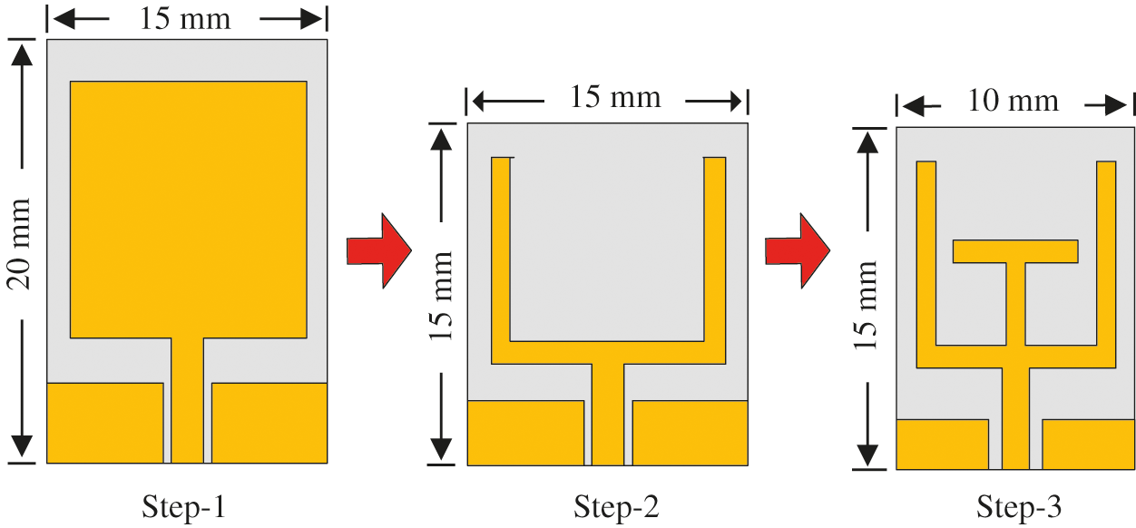
Figure 1: Design methodology of the proposed UWB antenna
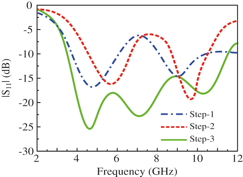
Figure 2: |S11| characteristics of the various antenna designs
To further reduce the antenna's physical size, a rectangular slot is etched from the top center of the rectangular radiator. The etching of the slot results in the conversion of a rectangular shape antenna into a ‘Y’ shaped serpentine structure. This results in the further reduction of the antenna size and has a dimension of 15 mm × 15 mm, while maintaining the antenna performance. In literature, various techniques are adopted to achieve ultra-wideband. The open-end stub loading technique is widely studied, having the advantage of a simple structure with miniaturization [32–34]. Therefore, a ‘T’ shaped open-ended stub is added to the antenna to achieve a wide impedance bandwidth, as shown in Fig. 2. Various antenna parameters, including the stub, are optimized to achieve compact size along with ultra-wideband spectrum. The final antenna offers a compact size of 15 mm × 10 mm, which is 50% miniaturized compared to the primary rectangular shape antenna, coving wide impedance bandwidth of 3.6–11.8 GHz (shown in Fig. 2).
2.2 Design of Frequency Selective Surface (FSS)
The FSSs with various shapes have been investigated in the literature [35]. The proposed FSS design combines well-known FSS structures (square and circular rings) to achieve a stopband characteristic at a wideband frequency to reflect the back-radiations for gain enhancement (depicted in Fig. 3). The low values of the |S12| is suggesting the passband (transmission type) nature of FSS, while its high values show the stopband (reflective type) FSS. Initially, a square looped unit element is designed and optimized, which gives a band stop function only at high frequencies, from 7–12 GHz, as shown in Fig. 4. Next, a circular loop is designed, and parameters are tuned to shift the stopband region to lower frequencies, that is from 3 to 8 GHz. Finally, both designs (square and circular rings) are integrated to develop a new kind of dual-loop FSS (shown in Fig. 3). This design has properties of both individual loops. Thus, a wide stopband from 2.8–12 GHz is obtained to reflect all the backward radiations to the broadside direction for improvement in gain.
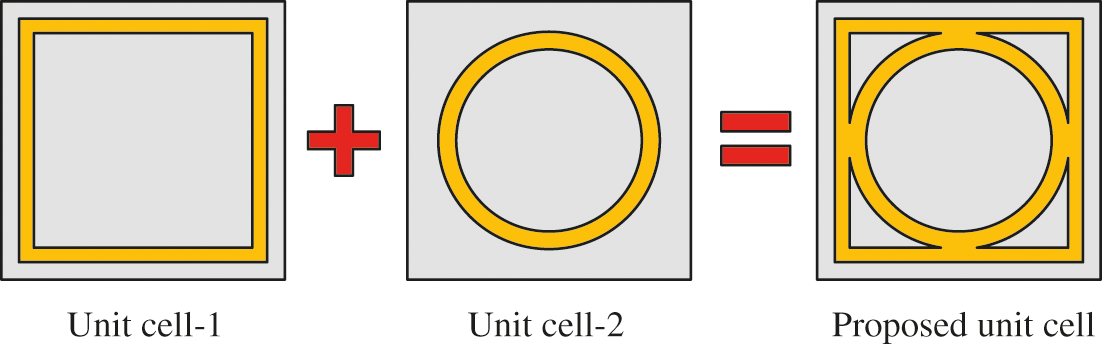
Figure 3: |S11| characteristics of the various antenna designs
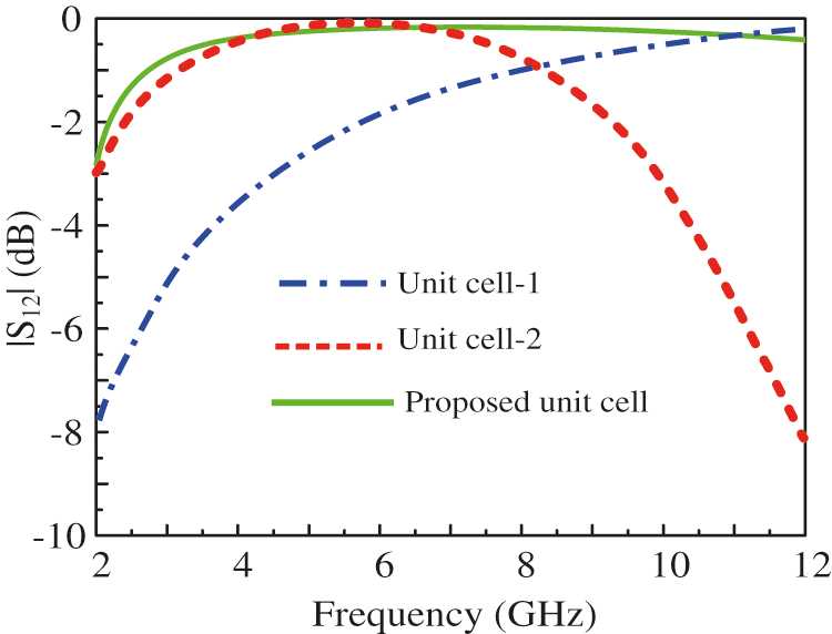
Figure 4: |S11| characteristics of the various antenna designs
2.3 Proposed FSS Loaded UWB Antenna
2.3.1 Geometrical Configuration of FSS Loaded Antenna
The geometrical configuration of the proposed UWB antenna and the antenna with FSS is shown in Figs. 5 and 6, respectively. The antenna and the FSS are printed on commercially available substrate material FR-4 having relative permittivity (εr), thickness, and loss tangent (tan δ) of 4.4, 1.6 mm, and 0.02, respectively. The overall size of the proposed CPW fed antenna is WS × LS × H (10 mm × 15 mm × 1.6 mm), which refers to the low profile and compact size (Fig. 5). The final design of the antenna consists of the FSS (designed in Section 2.2) and the UWB monopole. The antenna is placed above the FSS at the separation of s to reflect radiations for gain enhancement. Proposed UWB antenna as well as FSS is designed using Higher Frequency Structure Simulator (HFSS). The optimized parameters of proposed UWB antenna and FSS are as follow: Ls = 1.5; L1 = 6; L2 = 9.5; L3 = 1.5; L4 = 1; Ws = 10; a = 1; b = 1; s = 1; g = 5; h = 1.6; Cx = 4; Cy = 3.5; Ax = 5; Ay = 40; R1 = 2.25; R2 = 2; Fp = 4.5; d = 0.25; Mx = 40; s = 30 (units are in mm).
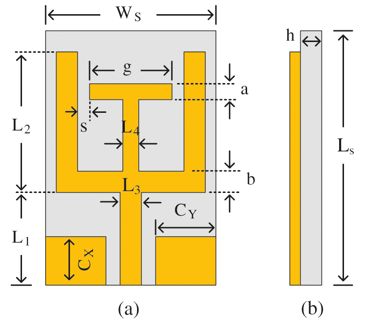
Figure 5: Geometrical configuration of proposed antenna (a) top-view (b) side-view
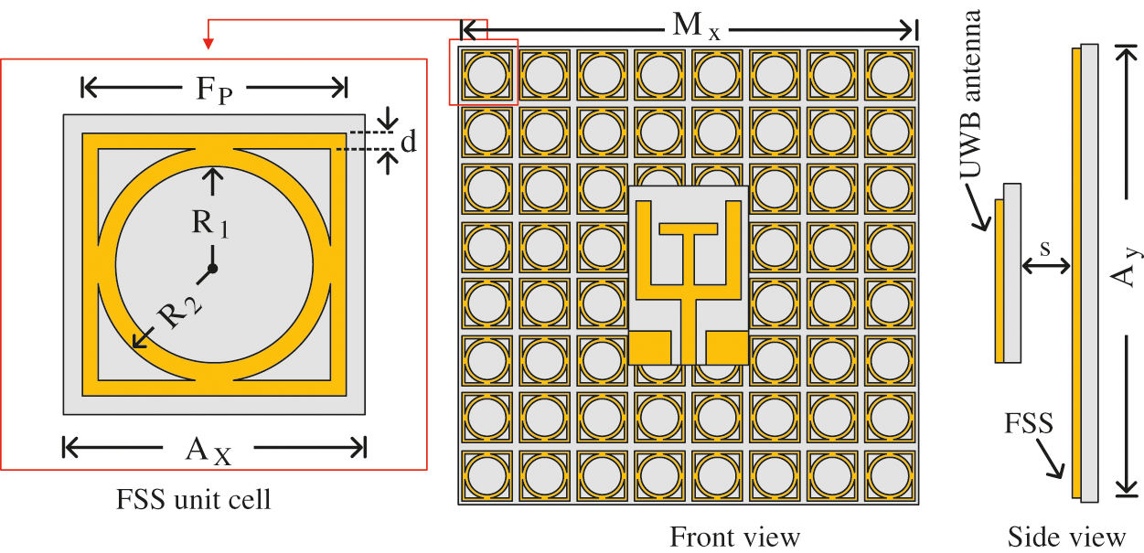
Figure 6: The geometrical configuration of the proposed FSS loaded UWB antenna (s = 30 mm)
2.3.2 Radiation Mechanism of the Antenna
The working principle of the proposed FSS loaded antenna is discussed in this section. The FSS is placed below the antenna to reflect the antenna's radiation coming in the backward direction. The antenna's gain increases when the reflected waves by FSS are in phase with the radiation by the antenna. Therefore, an essential factor is a gap between the UWB antenna and the proposed FSS, ensuring the constructive interference of reflected waves with directly radiated waves from the antenna. The following equation gives the approximate gap between the antenna and the FSS [36,37]:
The gap between the unit cell and FSS must be an integer multiple of the wavelength at the central frequency. However, due to the wideband nature of FSS, the distance between the FSS layer and antenna is optimized to achieve maximum gain. The proposed antenna is placed on the top side of 8 × 8 array of 64-unit elements FSS, which is assembled by replication of the unit cell, as depicted in Fig. 6. The optimized value shows that the gap between FSS and antenna is 30 mm. The reflection coefficient and gain of the proposed UWB antenna with and with FSS is depicted in Fig. 7. The antenna without FSS operates at the wide band of 3.6–11.8 GHz, having a peak gain of 3.8 dBi. On the other hand, when the FSS is placed below the proposed antenna, the antenna offers improved bandwidth ranging from 2.61 to 13 GHz and a minimum peak gain of more than 5.4 dBi. It is noted that the reflector size comparable with the size of the antenna does not reflect the entire back-radiations. This means that the gain increment is limited with the smaller reflector size. With the larger size of the reflector (FSS), more backward radiation can be reflected, increasing the gain significantly. It is observed that 8 × 8-unit cell FSS offers optimal gain improvement.
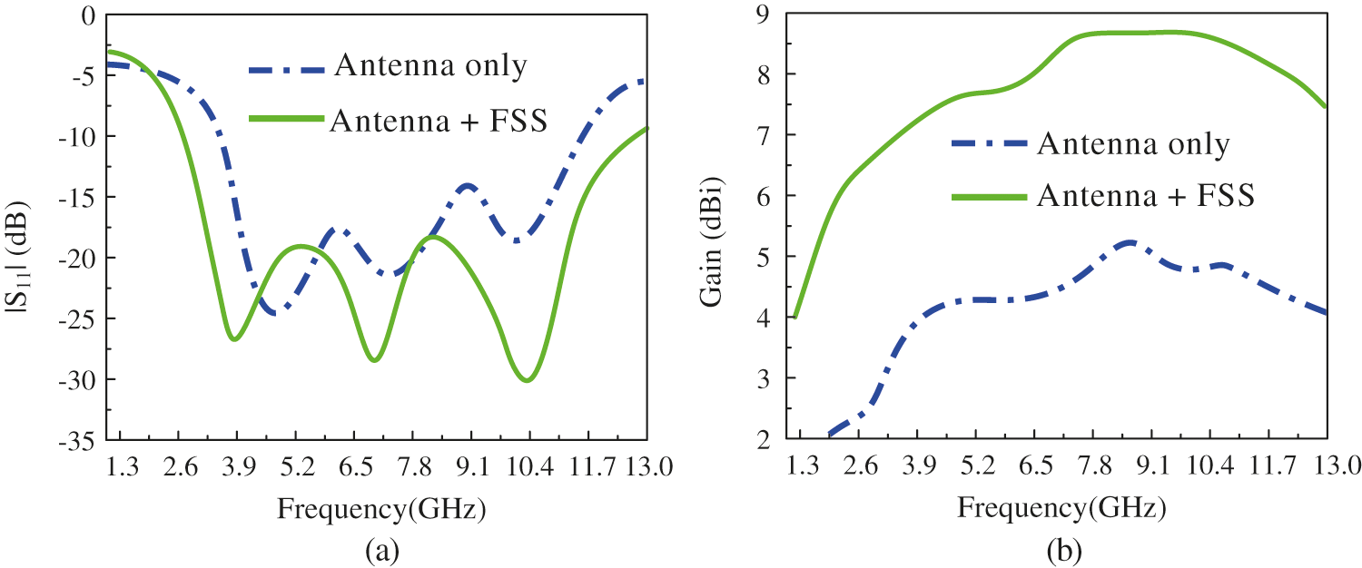
Figure 7: Simulated results of the antenna with and without FSS: (a) |S11| and (b) gain
The hardware prototype of the proposed antenna and antenna loaded with FSS are shown in Fig. 8 shows. The |S11| of the antennas are measured using Vector Network Analyzer (M9375A PXI) by KEYSIGHT Tech, having the operating range of 300 kHz to 26.5 GHz. A Styrofoam of 30 mm thickness is utilized carefully to realize the space between the antenna and FSS, as depicted in Fig. 8b. The foam is used due to its negligible effects on the performance of the antenna. The far-field characteristics of the proposed design are measured in a shielded anechoic chamber with the reference horn antenna placed at a distance of 3 meters. The measurement setup is set in such a way that the proposed antenna is placed at the receiver end and the horn antenna at the transmitter end.
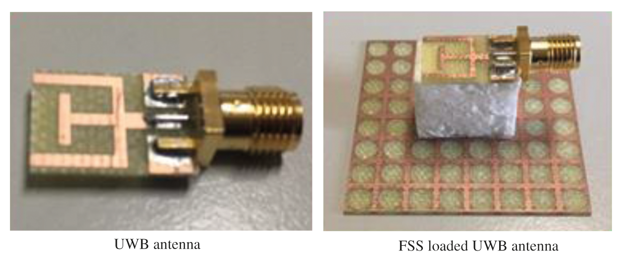
Figure 8: Fabricated prototype of the FSS loaded antenna
The comparison between the measured and simulated reflection coefficient |S11| of the proposed FSS loaded UWB antenna, and the antenna alone is plotted in Fig. 9. It can be observed that the simulated result of the antenna without FSS offers −10 dB impedance bandwidth of 8.2 GHz ranging 3.6–11.8 GHz. At the same time, the measured result offers |S11| < –10 dB impedance bandwidth of 8.7 GHz (3.4–12.1 GHz), which corresponds to 145% of fractional bandwidth for a central frequency of 6 GHz. On the other hand, the proposed antenna with FSS exhibits a wider –10 dB simulated and measured bandwidth of 2.55–13 GHz and 2.3–13.6 GHz, respectively. Generally, in both cases, a good agreement is observed for simulated and measured results.
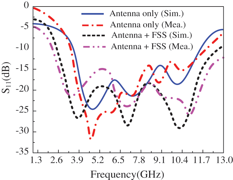
Figure 9: Simulated and measured |S11| of the antenna with and without FSS
The simulated and measured radiation patterns of the ultra-wideband antenna (without FSS) at the selected frequencies of 5.2 and 8.8 GHz are shown in Fig. 10. The antenna exhibits an omnidirectional radiation pattern along H-plane for both frequencies, while a bi-directional radiation pattern was observed for the principal E-plane. The strong agreement between simulated and measurement results was achieved by using SMA connector modal and antenna in simulations just like the one utilized for measurement purposes which significantly reduces the mismatch.
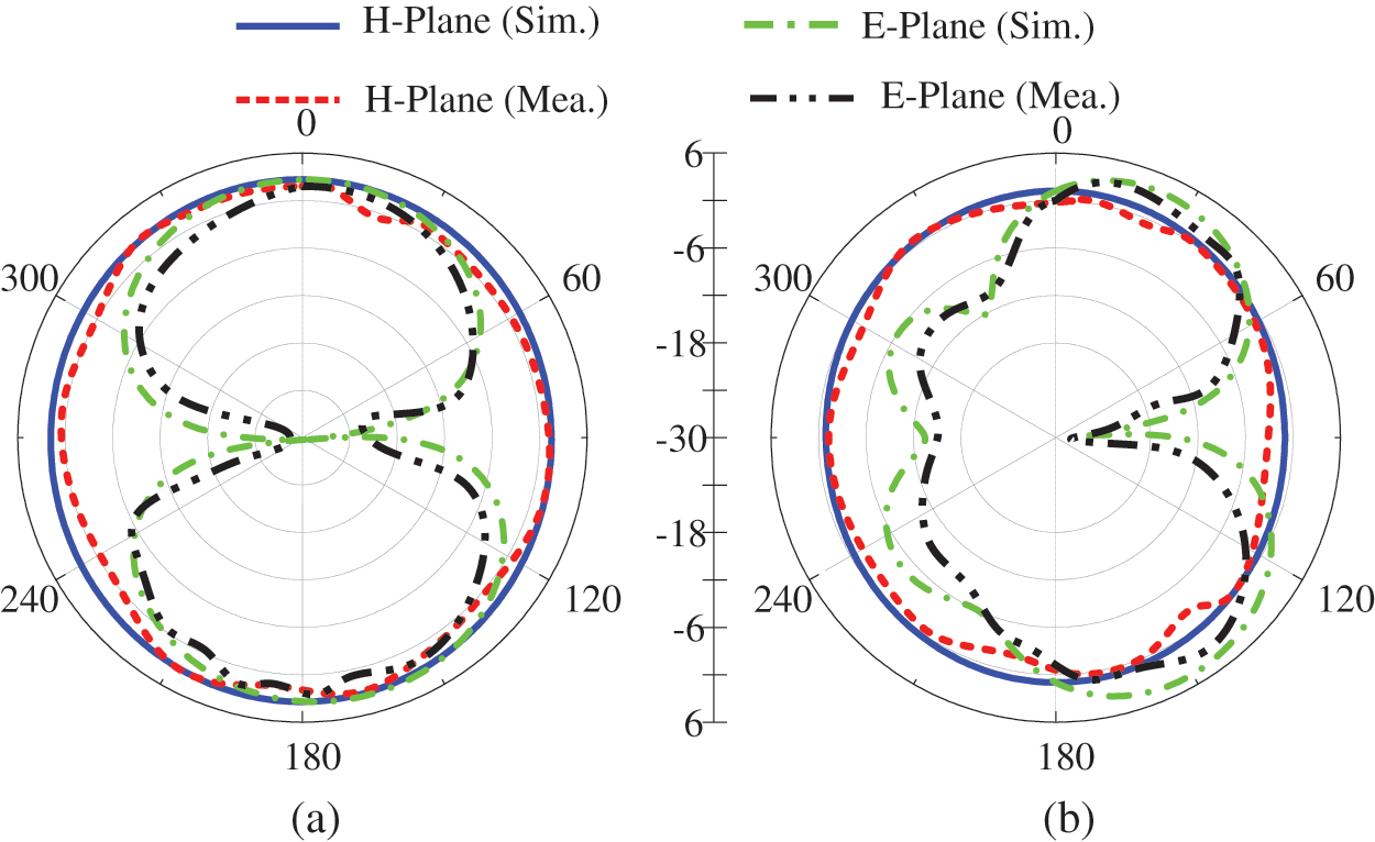
Figure 10: Radiation patterns of the UWB antenna without FSS (a) 5.2 GHz (b) 8.8 GHz
Fig. 11 demonstrates the surface current distribution of the proposed antenna at various selected frequencies. It could be observed that at the lower frequency of 5.2 GHz, the current is concentrated at the outer Y-shaped radiator, as depicted in Fig. 11a. On the other hand, at the higher frequency of 8.8 GHz, the surface current is concentrated at the bottom of the T-shaped stub, as shown in Fig. 11b. This effect is due to the phenomenon of the effective electrical length of the antenna, higher the frequency lower will be the electrical length, or vice versa.
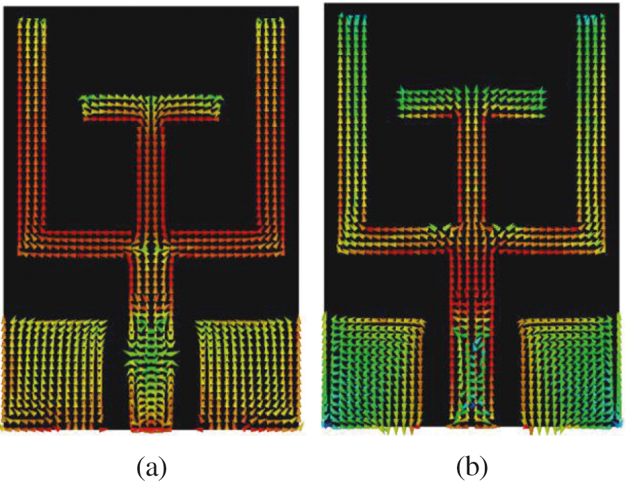
Figure 11: Surface current distribution of the UWB antenna at (a) 5.2 GHz (b) 8.8 GHz
On the other hand, when FSS is loaded at the backside of the antenna, FSS reflects all the electromagnetic waves (EM) coming from the antenna. The reflected EM waves constructively interfere with EM wave propagated upside of the antenna, due to which a broadside radiation pattern is noticed, as depicted in Fig. 12. The simulated and measured results of the antenna with FSS offer broadside radiation patterns at both selected frequencies. The backward radiations of the FSS loaded antenna can be further reduced by utilizing low-loss materials at the cost of a higher price.
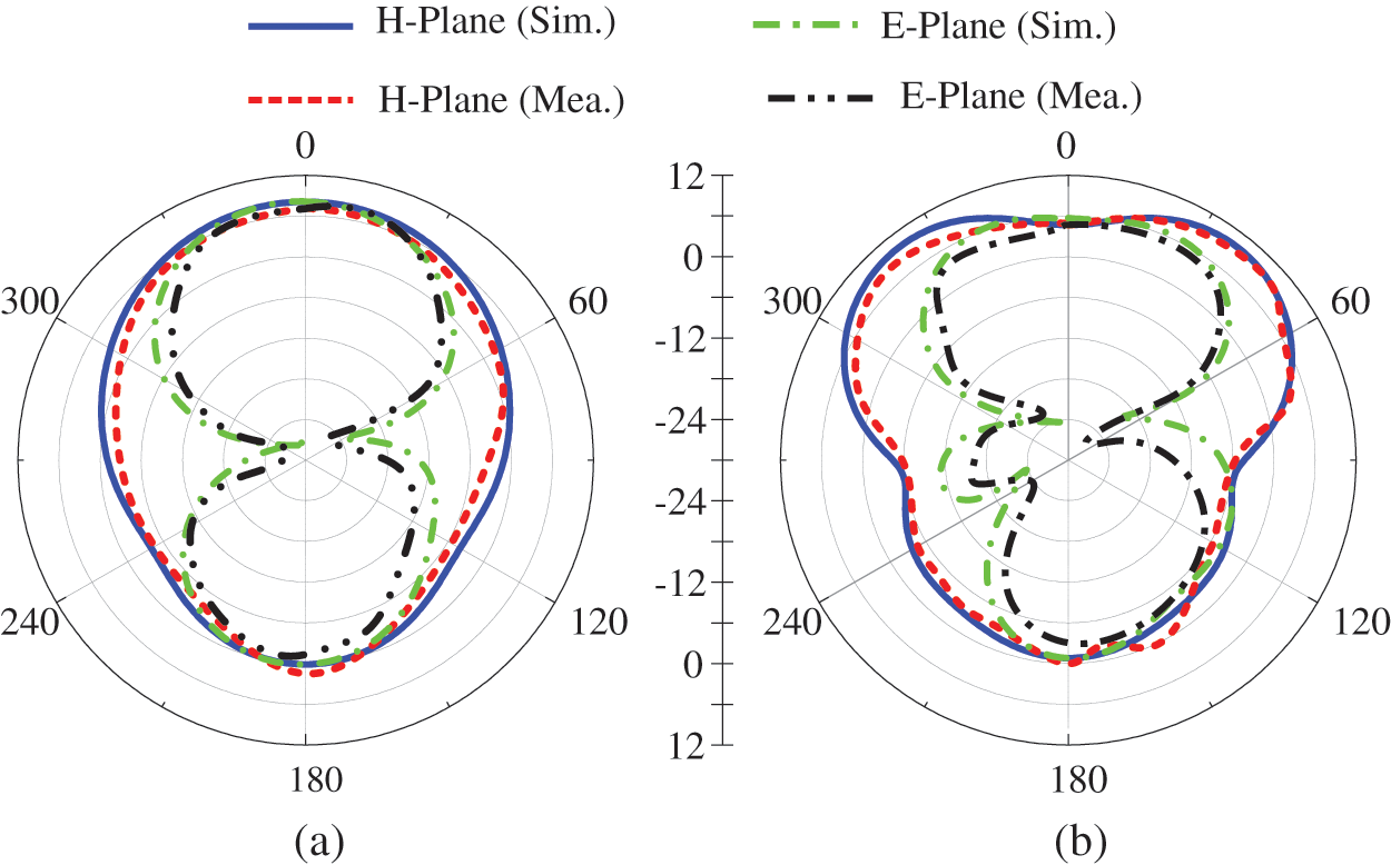
Figure 12: Radiation patterns of the proposed FSS loaded antenna (a) 5.2 GHz (b) 8.8 GHz
The gain of the antenna with and without FSS is shown in Fig. 13a. The antenna without FSS offers a gain of more than 2.5 dBi in the resonating area, having a peak value of 4.7 dBi. However, when the FSS has loaded with an antenna, the gain of the antenna increases significantly with an average increase of 4 dBi in the frequency range of interest. The FSS loaded antenna offers a peak value of 8.6 dBi at 8.8 GHz, while a minimum of 6 dBi is observed at 2.25 GHz. The strong agreement between simulated and measured results shows the performance stability of the proposed antenna. The antenna's total efficiency as a function of the frequency is shown in Fig. 13b. The efficiency is more than < 82% in the entire frequency range of interest due to the good impedance matching.
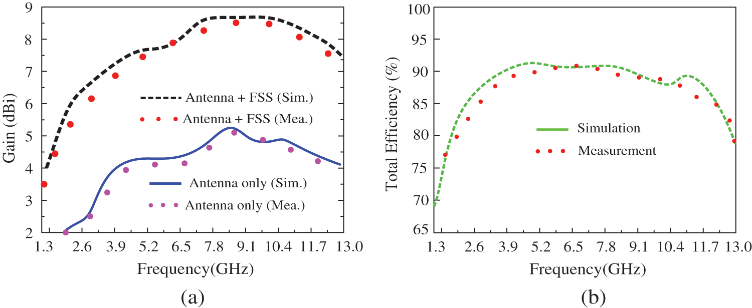
Figure 13: Simulated and measured: (a) gain and (b) efficiency of the antenna
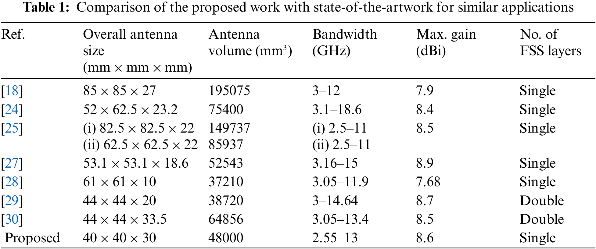
To demonstrate the potential of the proposed FSS loaded UWB antenna, the antenna's performance is compared with relevant state-of-the-art works (Tab. 1). The proposed antenna has an overall size of 40 × 40 × 30 mm3, which is smaller than the antennas shown in [18,24,25,27,30], except the antennas presented in [28,29]. However, the antenna in [28] has the disadvantages of narrow bandwidth and lower gain. Also, the antenna design given in [29], consists of double-layer FSS, which significantly increases the structural complexity. Thus, the proposed FSS loaded antenna offers a compact size, high gain, and broader bandwidth, making it a strong candidate for UWB applications requiring high gain characteristics.
The design, characterization, and measurement of an FSS loaded antenna for ultra-wideband and high gain applications is presented. The UWB antenna is extracted from a conventional CPW fed rectangular shape quarter-wave monopole antenna with the help of a rectangular slot and open-ended ‘T’ shaped stub. The monopole shows 50% miniaturization compared to a primary rectangular patch antenna with a wide impedance bandwidth of 3.6–11.8 GHz. Later, an FSS of 8 × 8-unit cells are designed by integrating well-known square and circular loop shape FSSs and placed under the antenna for performance enhancement. Due to the FSS, at least 4 dBi increment in gain is improved in the entire frequency range of interest. Moreover, the FSS loaded antenna offers wide –10 dB impedance bandwidth ranges 2.55–13 GHz with a peak gain of 8.6 dBi. The strong comparison among simulated and measured results of various performance parameters of the proposed work demonstrates the performance stability of the presented work. The performance comparison shows that this antenna offers the advantages of simple geometrical configuration, wide bandwidth, and high gain, making it a strong candidate for applications requiring high gain characteristics.
Funding Statement: This work was supported by an Institute for Information and Communications Technology Promotion (IITP), funded by the Korea government (MSIP) (No. 2021-0-00490, Development of precision analysis and imaging technology for biological radio waves).
Conflicts of Interest: The authors declare that they have no conflicts of interest to report regarding the present study.
References
1. H. Arslan, Z. N. Chen and M. G. Di Benedetto, Ultra-wideband Wireless Communication, Hoboken, NJ, USA: John Wiley & Sons, 2006. [Google Scholar]
2. P. A. Catherwood and W. G. Scanlon, “Ultrawideband communications—an idea whose time has still yet to come? [wireless corner],” IEEE Antennas and Propagation Magazine, vol. 57, no. 2, pp. 38–43, 2015. [Google Scholar]
3. E. M. Staderini, “UWB radars in medicine,” IEEE Aerospace and Electronic Systems Magazine, vol. 17, no. 1, pp. 13–18, 2002. [Google Scholar]
4. A. Haider, M. Rahman, H. Ahmad, M. NaghshvarianJahromi, M. T. Niaz et al., “Frequency-agile WLAN notch UWB antenna for URLLC applications,” CMC-Computers, Materials & Continua, vol. 67, no. 2, pp. 2243–2254, 2021. [Google Scholar]
5. M. A. Shahzad, K. N. Paracha, S. Naseer, S. Ahmad, M. Malik et al., “An artificial magnetic conductor-backed compact wearable antenna for smart watch IoT applications,” Electronics, vol. 10, no. 23, pp. 2908, 2021. [Google Scholar]
6. N. A. Jan, S. H. Kiani, F. Muhammad, D. A. Sehrai, A. Iqbal et al., “V-Shaped monopole antenna with chichena itzia inspired defected ground structure for UWB applications,” CMC-Computers, Materials & Continua, vol. 65, no. 1, pp. 19–32, 2020. [Google Scholar]
7. S. Ahmad, K. N. Paracha, Y. A. Sheikh, A. Ghaffar, A. D. Butt et al. “A Metasurface-based single-layered compact AMC-backed dual-band antenna for off-body IoT devices,” IEEE Access, vol. 9, pp. 159598–159615, 2021. [Google Scholar]
8. J. N. A. Jan, S. H. Kiani, D. A. Sehrai, M. R. Anjum, A. Iqbal et al., “Design of a compact monopole antenna for UWB applications,” CMC-Computers, Materials & Continua, vol. 66, no. 1, pp. 35–44, 2021. [Google Scholar]
9. H. Askari, N. Hussain, D. Choi, M. A. Sufian, A. Abbas et al., “An AMC-based circularly polarized antenna for 5G sub-6 GHz communications,” CMC-Computers, Materials & Continua, vol. 69, no. 3, pp. 2997–3013, 2021. [Google Scholar]
10. D. Yadav and V. Tiwari, “UWB antenna designing challenges and solutions,” International Journal of Computing, Communications & Instrumentation Engineering, vol. 1, no. 1, pp. 39–42, 2014. [Google Scholar]
11. C. Ramakrishna, G. A. E. S. Kumar and P. C. S. Reddy, “Quadruple band-notched compact monopole UWB antenna for wireless applications,” Journal of Electromagnetic Engineering and Science, vol. 21, no. 5, pp. 406–416, 2021. [Google Scholar]
12. B. R. Shookooh, A. Monajati and H. Khodabakhshi, “Theory, design, and implementation of a new family of ultra-wideband metamaterial microstrip array antennas based on fractal and fibonacci geometric patterns,” Journal of Electromagnetic Engineering and Science, vol. 20, no. 1, pp. 53–63, 2020. [Google Scholar]
13. M. Jeong, N. Hussain, H. Bong, J. W. Park, K. S. Shin et al., “Ultrawideband microstrip patch antenna with quadruple band notch characteristic using negative permittivity unit cells,” Microwave and Optical Technology Letters, vol. 62, no. 2, pp. 816–824. 2020. [Google Scholar]
14. H. Bong, M. Jeong, N. Hussain, S. Y. Rhee, S. K. Gil et al., “Design of an UWB antenna with two slits for 5G/WLAN-notched bands,” Microwave and Optical Technology Letters, vol. 61, no. 5, pp. 1295–1300, 2019. [Google Scholar]
15. Z. Li, X. Zhu and C. Yin, “CPW-Fed ultra-wideband slot antenna with broadband dual circular polarization,” AEU-International Journal of Electronics and Communications, vol. 98, pp. 191–198, 2019. [Google Scholar]
16. P. Soothar, H. Wang, B. Muneer, Z. A. Dayo and B. S. Chowdhry, “A broadband high gain tapered slot antenna for underwater communication in microwave band,” Wireless Personal Communications, vol. 116, no. 2, pp. 1025–1042, 2019. [Google Scholar]
17. Z. M. Yan, Y. S. Xu and W. D. Wang, “A compact tapered slot antenna for ultrawideband applications,” Microwave and Optical Technology Letters, vol. 55, no. 2, pp. 295–299, 2013. [Google Scholar]
18. F. A. Tahir, T. Arshad, S. Ullah and J. A. Flint, “A novel FSS for gain enhancement of printed antennas in UWB frequency spectrum,” Microwave and Optical Technology Letters, vol. 59, no. 10, pp. 2698–2704, 2017. [Google Scholar]
19. X. Zhu, X. Yang, Q. Song and B. Lui, “Compact UWB-MIMO antenna with metamaterial FSS decoupling structure,” EURASIP Journal on Wireless Communications and Networking, vol. 1, pp. 1–6, 2017. [Google Scholar]
20. Y. Zhu, Y. Chen and S. Yang, “Decoupling and low-profile design of dual-band dual-polarized base station antennas using frequency-selective surface,” IEEE Transactions on Antennas and Propagation, vol. 67, no. 8, pp. 5272–5281, 2019. [Google Scholar]
21. R. S. Anwar, L. Mao and H. Ning, “Frequency selective surfaces: A review,” Applied Sciences, vol. 8, no. 9, pp. 1689, 2018. [Google Scholar]
22. B. A. Munk, Frequency Selective Surfaces: Theory and Design, Hoboken, NJ, USA: John Wiley & Sons, 2005. [Google Scholar]
23. S. Narayan, B. Sangeetha and R. M. Jha, “Frequency selective surfaces based high performance microstrip antenna,” in Frequency Selective Surfaces Based High Performance Microstrip Antenna, Singapore: Springer, pp. 1–40, 2016. [Google Scholar]
24. R. Mondal, P. S. Reddy, D. C. Sarkar and P. P. Sarkar, “Compact ultra-wideband antenna: Improvement of gain and FBR across the entire bandwidth using FSS,” IET Microwaves, Antennas & Propagation, vol. 14, no. 1, pp. 66–74, 2019. [Google Scholar]
25. Y. Yuan, X. Xi and Y. Zhao. “Compact UWB FSS reflector for antenna gain enhancement,” IET Microwaves, Antennas & Propagation, vol. 13, no. 10, pp. 1749–1755, 2019. [Google Scholar]
26. R. A. Abdulhasan, R. Alias, K. N. Ramli, F. C. Seman and R. A. Abd-Alhameed, “High gain CPW-fed UWB planar monopole antenna-based compact uniplanar frequency selective surface for microwave imaging,” International Journal of RF and Microwave Computer-Aided Engineering, vol. 29, no. 8, pp. 21757, 2019. [Google Scholar]
27. A. Swetha and K. R. Naidu. “Gain enhancement of an UWB antenna based on a FSS reflector for broadband applications,” Progress in Electromagnetics Research, vol. 99, pp. 193–208, 2020. [Google Scholar]
28. A. J. Al-Gburi, I. B. M. Ibrahim, M. Y. Zeain and Z. Zakaria, “Compact size and high gain of CPW-fed UWB strawberry artistic shaped printed monopole antennas using FSS single layer reflector,” IEEE Access, vol. 8, pp. 92697–92707, 2020. [Google Scholar]
29. S. Kundu, A. Chatterjee, S. K. Jana and S. K. Parui, “Gain enhancement of a printed leaf shaped UWB antenna using dual FSS layers and experimental study for ground coupling GPR applications,” Microwave and Optical Technology Letters, vol. 60, no. 6, pp. 1417–1423, 2018. [Google Scholar]
30. S. Kundu, A. Chatterjee, S. K. Jana and S. K. Parui, “A compact umbrella-shaped UWB antenna with gain augmentation using frequency selective surface,” Radioengineering, vol. 27, no. 2, pp. 448–454, 2018. [Google Scholar]
31. W. Naktong and A. Ruengwaree, “Four-port rectangular monopole antenna for UWB-MIMO applications,” Progress in Electromagnetics Research B, vol. 87, pp. 19–38, 2020. [Google Scholar]
32. Y. H. Zhang, R. J. Spiegel, Y. Fan, W. T. Joines, Q. H. Liu et al., “Design of a stub-loaded ring-resonator slot for antenna applications,” IEEE Transactions on Antennas and Propagation, vol. 63, no. 2, pp. 517–524, 2014. [Google Scholar]
33. R. K. Verma and D. K. Srivastava, “Bandwidth improvement of stub loaded compact ultra-wideband microstrip patch antenna for C/X-band applications,” Wireless Personal Communications, vol. 128, pp. 185–202, 2021. [Google Scholar]
34. W. J. Lu and L. Zhu, “Wideband stub-loaded slot line antennas under multi-mode resonance operation,” IEEE Transactions on Antennas and Propagation, vol. 63, no. 2, pp. 818–823, 2014. [Google Scholar]
35. W. Mohyuddin, D. H. Kim, H. C. Choi and K. W. Kim, “Comparative study of square and circular loop frequency selective surfaces for millimeter-wave imaging diagnostics systems,” Sensors, vol. 18, no. 9, pp. 3079, 2018. [Google Scholar]
36. N. Hussain, M. Jeong, J. Park and N. Kim, “A broadband circularly polarized Fabry-Perot resonant antenna using a single-layered PRS for 5G MIMO applications,” IEEE Access, vol. 7, pp. 42897–42907, 2019. [Google Scholar]
37. N. Hussain, M. Jeong, A. Abbas, T. Kim and N. Kim, “A Metasurface-based low-profile wideband circularly polarized patch antenna for 5G millimeter-wave systems,” IEEE Access, vol. 8, pp. 22127–22135, 2020. [Google Scholar]
 | This work is licensed under a Creative Commons Attribution 4.0 International License, which permits unrestricted use, distribution, and reproduction in any medium, provided the original work is properly cited. |