| Computers, Materials & Continua DOI:10.32604/cmc.2022.027862 | |
| Article |
A Constant Gain and Miniaturized Antipodal Vivaldi Antenna for 5G Communication Applications
1Symbiosis Institute of Technology, Symbiosis International (Deemed University), Pune, 412115, India
2Department of Electrical Engineering, College of Engineering, Princess Nourah bint Abdulrahman University, P. O. Box 84428, Riyadh, 11671, Saudi Arabia
*Corresponding Author: Sumit Kumar. Email: er.sumitkumar21@gmail.com
Received: 27 January 2022; Accepted: 16 March 2022
Abstract: This paper proposes a stable gain and a compact Antipodal Vivaldi Antenna (AVA) for a 38 GHz band of 5G communication. A novel compact AVA is designed to provide constant gain, high front to back ratio (FBR), and very high efficiency. The performance of the proposed AVA is enhanced with the help of a dielectric lens (DL) and corrugations. A rectangular-shaped DL is incorporated in conventional AVA (CAVA) to enhance its gain up to 1 dBi and the bandwidth by 1.8 GHz. Next, the rectangular corrugations are implemented in CAVA with lens (CAVA-L) to further improve the gain and bandwidth. The proposed AVA with lens and corrugations (AVA-LC) gives a constant and high gain of 8.2 to 9 dBi. The designed AVA-LC operates from 34 to 45 GHz frequency which covers 38 GHz (37.5 to 43.5 GHz) band of 5G applications. Further, the presented AVA-LC mitigates the back lobe and sidelobe levels, resulting in FBR and efficiency improvement. The FBR is in the range of 12.2 to 22 dB, and efficiency is 99%, almost constant. The AVA-LC is fabricated on Roger’s RT/duroid 5880 substrate, and it is tested to verify the simulated results. The proposed compact AVA-LC with high gain, an improved FBR, excellent efficiency, and stable radiation patterns is suitable for the 38 GHz band of 5G devices.
Keywords: Antipodal Vivaldi Antenna (AVA); constant gain; dielectric lens (DL); 5G communication; corrugations; front to back ratio (FBR)
Moving towards the next generation 5G communications, we require devices compatible with that. Most of the operating range of 5G communication lies above 24 GHz (25–29.5, 37.5–43.5 GHz), and with this higher frequency, 5G Communication requires an antenna with higher gain to compensate propagation losses [1,2]. Also, the antenna must operate with a minimum requirement of 5G communication bandwidth of 6–7 GHz [3,4]. Also, 5G communications device must operate with stable and constant gain with a unidirectional radiation pattern. With this set of parameters of the 5G communication device, choosing an antenna type that satisfies all these parameters becomes essential. As per the literature survey, various researchers have designed different antennas for 5G applications. In [5,6], two port multiple input multiple output (MIMO) microstrip patch antennas are designed for 5G devices. Next, planar helical antenna is designed in [7] for 28 GHz band of 5G applications. Further, T-shaped fractal antenna is designed in [8] for 5G Ka-band applications. Out of various reported antennas, antipodal Vivaldi antenna (AVA) with its known characteristics of broader bandwidth, higher efficiency, and higher gain helps to achieve the required parameters of 5G communications [9]. In 1979 Dr. Gibson introduced the concept of Vivaldi antenna [10] which was later on altered to Antipodal Vivaldi Antenna (AVA) by Dr. Gazit in 1988 [11]. Not only 5G communications AVA is employed in several other applications like ultra-wideband communication (UWB) [12], medical antennas [13,14], radar [15], civil engineering [16] and other mm-Wave and microwave applications [17].
As found in the literature, AVA is extensively employed in 5G communication devices [18,19]. As the 5G device size keeps on reducing, it becomes difficult to use AVA because of its larger size. So size reduction with keeping antenna 5G parameters intact becomes the most challenging part, motivating several researchers to do the same. Several techniques can be found in literature with options like dielectric lens [20], choice of substrate [21], metamaterial [22,23], parasitic patch [24], corrugation [25,26], and slots [27]. Moreover, the AVA array is also employed in several antenna designs where high gain is required but with the increased antenna size [28–30]. Multiple input multiple output (MIMO) antenna design is complex and it requires more size [31,32]. Next, the design and placement of the metamaterial unit cells are daunting tasks [33,34]. A small-sized parasitic patch gives a minimal increment in the gain, whereas the larger size of the parasitic patch increases the antenna size. The dielectric lens also increases the antenna size, but it gives more gain enhancement as compared to the parasitic patch [35,36].
In this work, AVA is designed with Rogers RT/duroid 5880 because of its low dielectric constant and low loss tangent; it is more suitable for the 5G application frequency range. Out of the various enhancement techniques proposed in the literature, dielectric lens and corrugation techniques have been employed in this work to make it more compact and to enhance its gain. The use of DL and corrugations effectively to give excellent efficiency and a constant gain are the novelties of the proposed design. The proposed AVA provides very high and constant efficiency of 99% which is not reported in earlier AVA designs. Also, the proposed AVA gives a constant gain of 8.6 ± 0.4 dBi and such gain stability is not reported in the literature. The paper is divided into 4 sections, where Section 1 is an introduction. In Section 2, the AVA-LC design is presented. Section 3 is the results and discussion where simulation and measured results are presented to compare AVA-LC with the other related antenna proposed in the literature. Finally, Section 4 concludes the work.
2 Antenna Design and Parametric Study
Fig. 1a represents the elementary structure of the conventional AVA (CAVA) of dimensions 20 mm × 6 mm designed using Rogers RT/duroid 5880 substrate with a height of 0.5 mm and dielectric constant of 2.2 [37]. The substrate’s loss tangent value is 0.009. Both the bottom and top patches are a mirror image of each other. The bottom and top patches act as ground and radiators, respectively. The impedance matching is done via the 50 Ω microstrip transmission line.
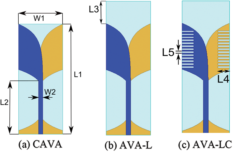
Figure 1: Proposed antenna designs
The Equations of the curves are given by
where
Here,
r = rate of increase of exponential curve
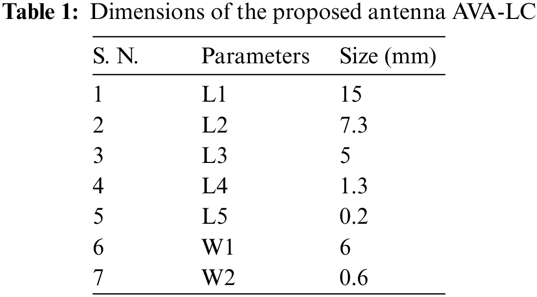
The antenna parameters optimum values are obtained using High-Frequency Structure Simulator (HFSS), version 2020. The parameters of AVA are listed in Tab. 1.
2.2 Lens and Corrugation Design
As per the literature survey done on AVA with dielectric lens, it is found that dielectric lens is of various shapes like rectangular, circular, elliptical, square, and trapezoidal. Authors have designed the AVA with different shapes of a dielectric lens to finalize the shape. Figs. 2a and 2b shows the reflection coefficients and directivity graphs of AVA with different DL shapes, respectively. Fig. 2a shows that circular shaped DL has a poor frequency response as compared to the other DL shapes. Next, there are no significant bandwidth variations for trapezoidal, ellipse, and square-shaped DL. Out of these DL shapes, rectangular-shaped DL provides better frequency response with −8 dB impedance bandwidth of 10.4 GHz. Further, Fig. 2b proves the contribution of rectangular-shaped DL in the directivity enhancement. The circular-shaped DL gives the least directivity as compared to other DL shapes. The ellipse-shaped DL provides moderate directivity. Both Figs. 2a and 2b prove that the rectangular-shaped DL is an appropriate choice.
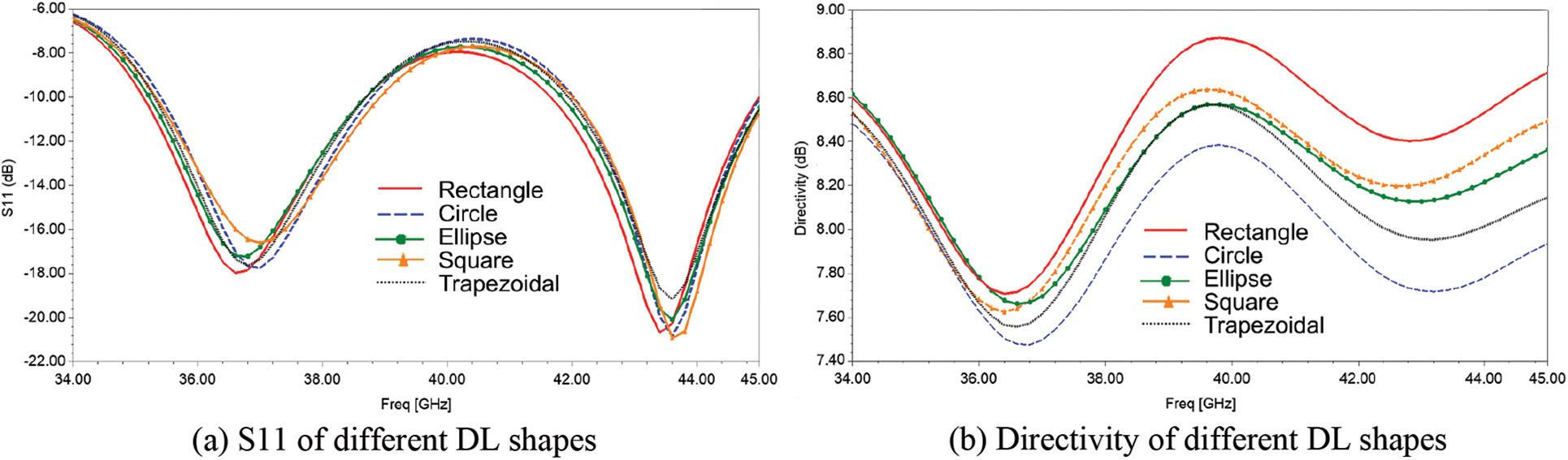
Figure 2: Results of AVA with different shapes of DL
Fig. 3 depict the reflection coefficients of AVA-L for various lengths of the rectangular lens. It can be seen from the Fig. 3 that as the lens length increase, the S11 also improves. The best return loss is obtained for L3 = 5 mm and hence considered for the final design which is shown in the Fig. 1b.
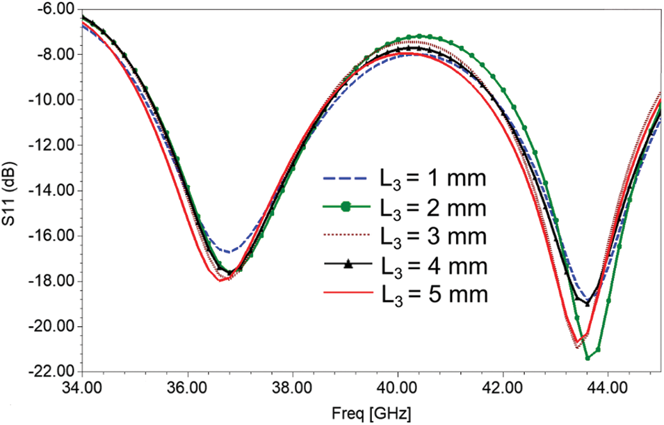
Figure 3: S11 for different lengths of DL
Next, to further enhance the parameters of AVA-L, corrugations are added in the AVA top and bottom patches as shown in the Fig. 1c. The parametric analysis for corrugation length is shown in the Fig. 4. In this Fig. 4, as corrugation length increases, the resonance frequency is shifted towards the low-frequency side. The better frequency responses are obtained at 37.2 and 43.6 GHz for L4 = 0.7 mm, but it has not included the required band from 38.9 to 42.2 GHz. This parametric analysis proves that the −10 dB wide bandwidth is provided by L4= 1.3 mm, from 37.5 GHz to above 45 GHz. Similarly, the corrugation’s width (L5) is optimized, and its optimum value is 0.2 mm.
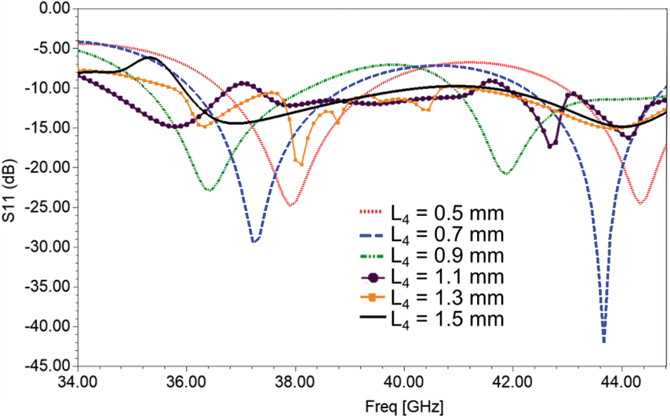
Figure 4: Effect of corrugations length
The corrugations are important for gain enhancement which is proved in Fig. 5. Figs. 5a and 5b are the electric field distribution at 38 GHz of AVA-L and AVA-LC respectively. It can be seen that in AVA-L, a more electric field is present at the exponential curve. In contrast, in AVA-LC, the electric field intensity is greater at exponential curves and at the corrugations. This increase in the e-field intensity of AVA-LC directs most of the radiations in the aperture direction resulting in the gain enhancement. Also, the proposed AVA-LC provides an improved electric field in the range of kV/m.
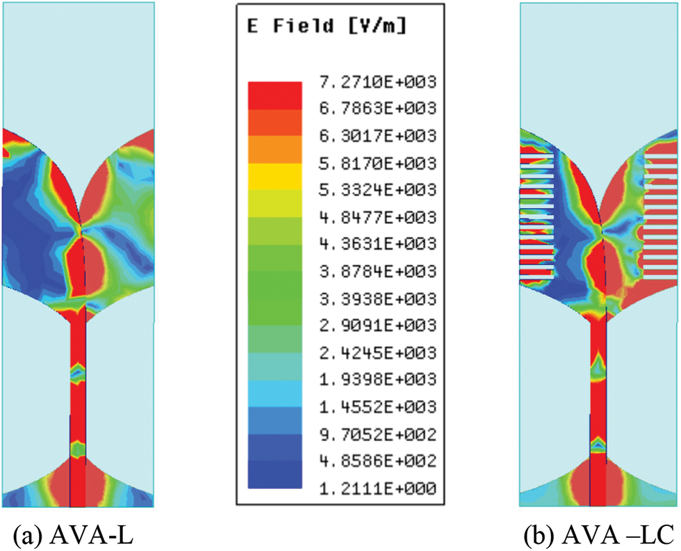
Figure 5: Electric field distribution at 38 GHz
The antenna is fabricated by using photolithography process. A Roger’s substrate 5880 which has 35 μm copper thicknesses on both sides was used for antenna fabrication. At first, the substrate is cleaned using acetone, deionized water, and isopropyl alcohol. Then the substrate was dehydrated and bottom surface was coated with PR SPR220-7. Next, the top patch was etched using ferric chloride solution. After this, the coating of bottom patch was removed and then patterning of bottom patch was done. The top and bottom views of the fabricated antenna are shown in Fig. 6.
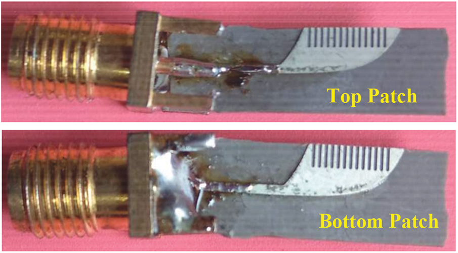
Figure 6: Fabricated proposed antenna
Next, Fig. 7 depict the S11 of CAVA, AVA-L, and AVA-LC. The CAVA has provided the lowest bandwidth. DL’s addition gave a dual-band that does not cover the center frequencies of the 38 GHz band of 5G applications. After incorporating the corrugations, the resistance, capacitance, and inductance values of an antenna change result in the change in return loss. The dimensions of corrugations are optimized such that the designed antenna can cover the entire 38 GHz band. The simulated frequency band is from 35.7 GHz to above 45 GHz.
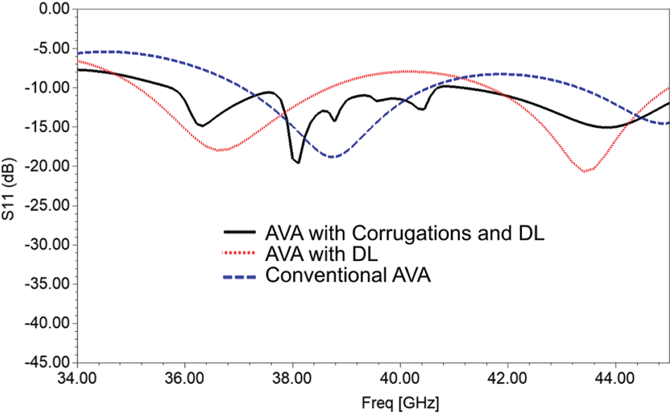
Figure 7: Reflection coefficients (S11) of the proposed antenna
The front-to-back ratio (FBR) plot is given in Fig. 8. There is no significant difference between CAVA and AVA-L FBR plots, which is in the range of 4.2 to 15.2 dB. The corrugations alleviate the back lobe level and improve the main lobe level, which improves the FBR. The proposed AVA-LC provides FBR in the range of 12.2 dB to 22 dB. This enhancement in FBR is reflected in the gain improvement as shown in the Fig. 9. As proved in the Fig. 9, the gain of CAVA is the lowest, which is from 5.75 to 6.9 dBi. The CAVA’s gain is improved up to 1 dBi by using DL. The corrugations further enhance the gain, and it is from 8.2 to 9 dBi. Thus the proposed antenna provides a high and constant gain. The increase in antenna’s gain also improves the efficiency as proved in Fig. 10. All the designed antennas provide efficiency higher than 86%. The designed AVA-LC gives high and a constant efficiency of 99%.
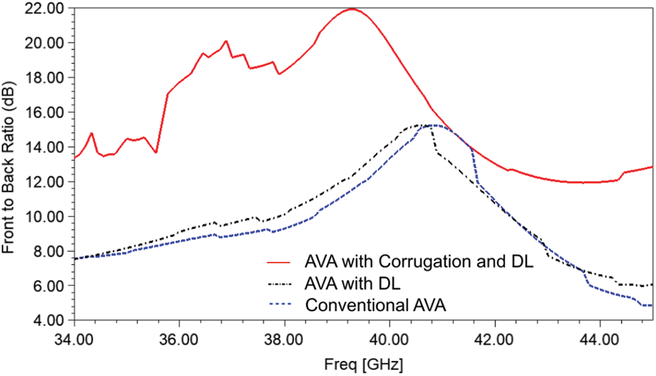
Figure 8: Front to back ratio vs. frequency plot
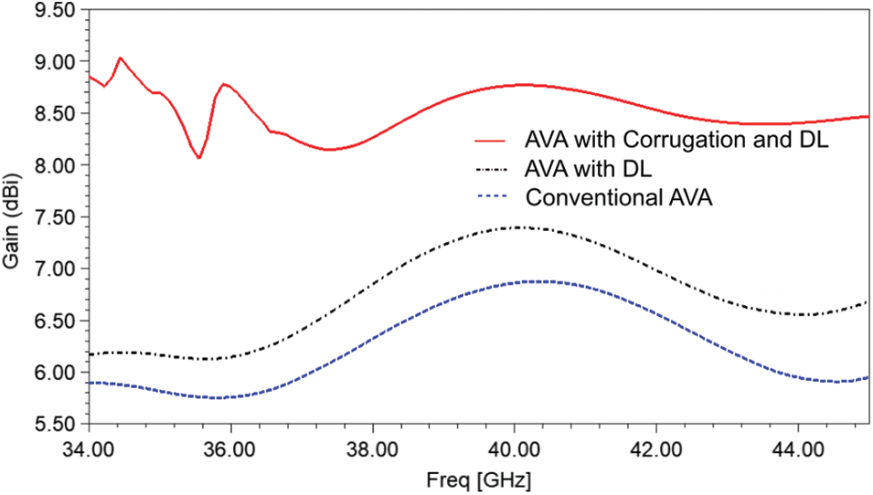
Figure 9: Gain vs. frequency plot
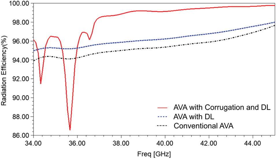
Figure 10: Radiation efficiency vs. frequency plot
The simulated AVA-LC is fabricated on RT/duroid 5880 substrate, and then it is tested by using a performance network analyzer (PNA) N5224B. Fig. 11a shows the experimental setup and (b) shows the plot of reflection coefficients. Initially, PNA was calibrated from 1 to 43.5 GHz, and then the antenna under test (AUT) was connected to the PNA’s port. The discrepancy between the results is due to the difference between the ideal simulation environment and practical lossy environment. The measured −10 dB impedance bandwidth is 34 GHz to above 43.5 GHz, whereas the simulated bandwidth is 35.7 to 45 GHz.
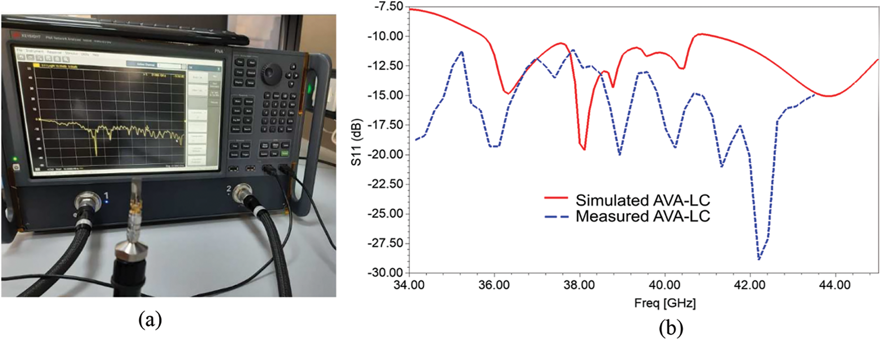
Figure 11: (a) Experimental setup to measure S11 (b) Measured and simulated S11
The radiation patterns are plotted in the Fig. 12. Figs. 12a–12c are azimuth planes (H plane), and Figs. 12d–12f are elevation planes (E plane) which are plotted at 37, 39, and 43.77 GHz respectively. These radiations patterns of AVA-LC are stable over the desired frequency band. For AVA-LC, the main lobe is the highest, and the back lobe level is the lowest compared to the other AVA designs. It also shows that the corrugations mitigate the sidelobe levels. In elevation planes, the size of the main lobe level is more at 43.77 GHz, and hence the gain is highest at 43.77 GHz. Moreover, the back lobe level is less at 39 GHz, and hence FBR is highest at 39 GHz.
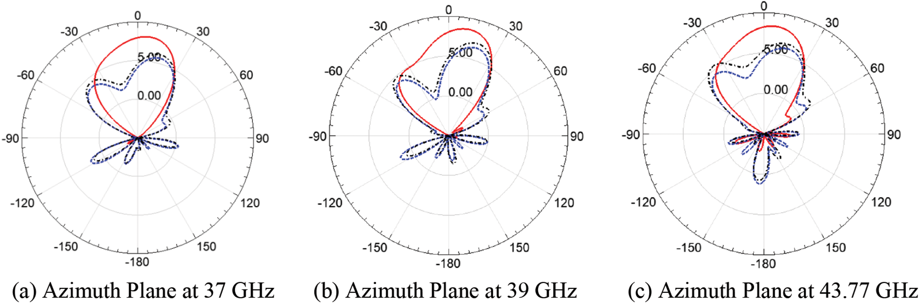
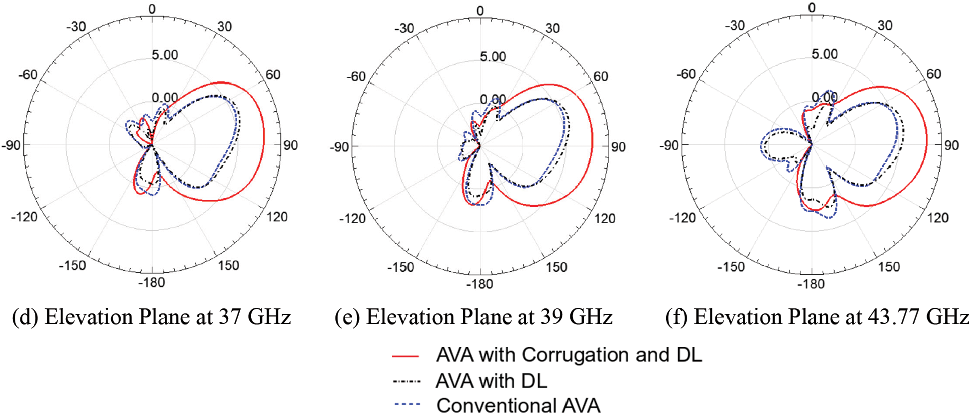
Figure 12: Simulated radiation pattern of the proposed antenna designs
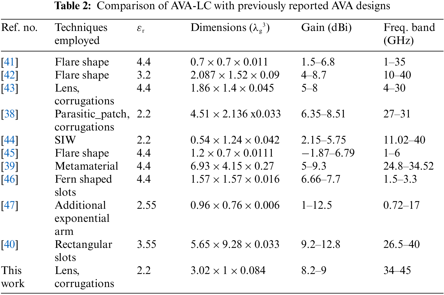
Tab. 2 shows the comparison of the proposed AVA-LC with previously reported AVAs. The comparison is made based on some important parameters like techniques employed for enhancement, relative permittivity (εr), antenna size in terms of guided wavelength, gain in dBi, and frequency range in GHz. Dimensions are calculated by considering the lowest operating frequency. The comparison Tab. 2 shows that the antennas designed by [38–40] are of larger size than the proposed AVA-LC. Next, other AVAs designed by [41–45] are comparatively smaller in size, but their gains are lower than the proposed AVA-LC. Further, the antenna designed in [46] gives less gain and narrower bandwidth. The AVA designed in [47] exhibits very large gain variations of 11.5 dBi which is practically not desirable. Also, the gain variations are more in all the above-reported antennas, whereas the proposed AVA-LC allows only ± 0.4 dBi gain variation. Hence, the proposed AVA-LC is a highly constant gain antenna. So, this Tab. 2 prove that the proposed AVA-LC is suitable for the 38 GHz band of 5G applications.
This paper enhances conventional AVA parameters by employing corrugations and a dielectric lens. The designed antenna has constant gain over the entire operating frequency range. The Experimental results validate the simulated results which are almost the same. The proposed antenna improves conventional AVA peak gain from 6.88 to 9 dBi. Also, it decreases the lower cut-off frequency from 37.07 to 34 GHz, which enhances the overall bandwidth from 5.15 to 11 GHz. Because of the employment of corrugations and dielectric lens in the designed antenna, the front-to-back ratio and efficiency are enhanced by reducing the sidelobe levels. The proposed novel antenna has the advantage of constant gain, high efficiency, and unidirectional radiation pattern over the entire operating frequency. So the designed antenna is one of the ideal candidates for 5G communication devices where constant gain and the stable radiation pattern with high efficiency are the major requirements.
Acknowledgement: Princess Nourah bint Abdulrahman University Researchers Supporting Project number (PNURSP2022R79), Princess Nourah bint Abdulrahman University, Riyadh, Saudi Arabia.
Funding Statement: This research was funded by Princess Nourah bint Abdulrahman University Researchers Supporting Project number (PNURSP2022R79), Princess Nourah bint Abdulrahman University, Riyadh, Saudi Arabia, S. Urooj, https://www.pnu.edu.sa.
Conflicts of Interest: The authors declare that they have no conflicts of interest to report regarding the present study.
References
1. S. Tariq, S. I. Naqvi, N. Hussain, Y. Amin, and S. Member, “A metasurface-based MIMO antenna for 5G millimeter-wave applications,” IEEE Access, vol. 9, pp. 51805–51817, 2021. [Google Scholar]
2. W. Abbas, A. Syeda, I. Naqvi, A. Hussain, N. Syed et al., “Design and characterization of wideband printed antenna based on DGS for 28 GHz 5G applications,” Journal of Electromagnetic Engineering and Science, vol. 21, no. 3, pp. 1–6, 2021. [Google Scholar]
3. S. Kumar, A. S. Dixit, R. R. Malekar, H. D. Raut and L. K. Shevada, “Fifth generation antennas: A comprehensive review of design and performance enhancement techniques,” IEEE Access, vol. 8, pp. 163568–163593, 2020. [Google Scholar]
4. H. Zahra, W. A. Awan, N. Hussain, S. M. Abbas and S. Mukhopadhyay, “Helix inspired 28 GHz broadband antenna with end-fire radiation pattern,” Computers, Materials & Continua, vol. 70, no. 1, pp. 1935–1944, 2021. [Google Scholar]
5. H. Khalid, “Design of an integrated sub-6 GHz and mmwave MIMO antenna for 5G handheld devices,” Appl. Sci., vol. 11, no. 18, pp. 1–21, 2021. [Google Scholar]
6. N. Hussain, W. A. Awan, W. Ali, S. I. Naqvi, A. Zaidi et al., “Compact wideband patch antenna and its MIMO configuration for 28 GHz applications,” AEU-Int. J. Electron. Commun., vol. 132, no. January, pp. 153612, 2021. [Google Scholar]
7. H. Zahra, W. A. Awan, W. A. E. Ali, N. Hussain, S. M. Abbas et al., “A 28 GHz broadband helical inspired end-fire antenna and its MIMO configuration for 5G pattern diversity applications,” Electron., vol. 10, no. 4, pp. 1–15, 2021. [Google Scholar]
8. W. A. Awan, M. Alibakhshikenari, and E. Limiti, “Design and analysis of a simple miniaturized fractal antenna for 5G Ka-band applications,” in 2021 IEEE Asia-Pacific Microwave Conf. (APMC), Brisbane, Australia, pp. 22–24, 2021. [Google Scholar]
9. S. Kumar and A. S. Dixit, “A bibliometric survey on antipodal Vivaldi antenna,” Librrary Philosophy and Practice, pp. 1–25, 2021. [Google Scholar]
10. P. J. Gibson, “The Vivaldi aerial,” in 9th European Microwave Conf., Brighton, UK, no. 1, pp. 101–105, 1979. [Google Scholar]
11. E. Gazit, “Improved design of the Vivaldi antenna,” IEE Proceedings H Microwaves, Antennas and Propagation, vol. 135, no. 2, pp. 89–92, 1988. [Google Scholar]
12. X. Zhang, Y. Chen, M. Tian, J. Liu and H. Liu, “A compact wide-band antipodal Vivaldi antenna design,” International Journal of RF and Microwave Computer-Aided Engineering, vol. 29, no. 4, pp. 1–6, 2018. [Google Scholar]
13. W. Shao and R. Adams, “Two antipodal Vivaldi antennas and an antenna array for microwave early breast cancer detection,” Microwwave Optical Technology Letters, vol. 55, no. 3, pp. 670–674, 2013. [Google Scholar]
14. B. J. Mohammed, A. M. Abbosh, S. Mustafa and D. Ireland, “Microwave system for head imaging,” IEEE Transacions on Instrumentation and Measurement, vol. 63, no. 1, pp. 117–123, 2014. [Google Scholar]
15. A. S. Dixit and S. Kumar, “A wideband antipodal Vivaldi antenna,” in 2021 7th Int. Conf. on Signal Processing and Communication (ICSC), Noida, India, pp. 11–14, 2021. [Google Scholar]
16. M. Moosazadeh, S. Kharkovsky, J. T. Case and B. Samali, “Improved radiation characteristics of small antipodal Vivaldi antenna for microwave and millimeter-wave imaging applications,” IEEE Antennas and Wireless Propagation Letters, vol. 16, pp. 1961–1964, 2017. [Google Scholar]
17. M. Moosazadeh, S. Kharkovsky, J. T. Case and B. Samali, “UWB antipodal Vivaldi antenna for microwave imaging of construction materials and structures,” Microwave Optical Technolgy Letters, vol. 59, no. 6, pp. 1259–1264, 2016. [Google Scholar]
18. H. Liu, W. Yang, A. Zhang, S. Zhu, Z. Wang et al., “A miniaturized gain-enhanced antipodal Vivaldi antenna and its array for 5G communication applications,” IEEE Access, vol. 6, pp. 76282–76288, 2018. [Google Scholar]
19. S. Zhu, H. Liu, Z. Chen and P. Wen, “A compact gain-enhanced Vivaldi antenna array with suppressed mutual coupling for 5G mmwave application,” IEEE Antennas and Wireless Propagation Letters, vol. 17, no. 5, pp. 776–779, 2018. [Google Scholar]
20. M. Moosazadeh, “High-gain antipodal Vivaldi antenna surrounded by dielectric for wideband applications,” IEEE Transactions on Antennas and Propagations, vol. 66, no. 8, pp. 4349–4352, 2018. [Google Scholar]
21. A. S. Dixit and S. Kumar, “A dual band antipodal Vivaldi antenna for fifth-generation applications,” in 2021 IEEE Indian Conf. on Antennas and Propagation (InCAP), Jaipur, India, pp. 224–227, 2021. [Google Scholar]
22. M. Hendy, S. El-Nady, H. M. Zamel, A. M. Attiya and A. H. A. Zekry, “Gain enhancement of a millimeter wave antipodal Vivaldi antenna by epsilon-near-zero metamaterial,” Progress in Electromagnetics Research C, vol. 85, no. May, pp. 105–116, 2018. [Google Scholar]
23. X. Li, H. Zhou, Z. Gao, H. Wang and G. Lv, “Metamaterial slabs covered UWB antipodal Vivaldi antenna,” IEEE Antennas and Wireless Propagation Letters, vol. 16, pp. 2943–2946, 2017. [Google Scholar]
24. J. Bang, J. Lee and J. Choi, “Design of a wideband antipodal Vivaldi antenna with an asymmetric parasitic patch,” Journal of Electromagnetic Engineering and Science, vol. 18, no. 1, pp. 29–34, 2018. [Google Scholar]
25. X. S. Loo, M. Z. Win and K. S. Yeo, “A high gain 60 GHz antipodal Fermi-tapered slot antenna based on robust synthesized dielectric,” Microwave Optical Technolgy Letters, vol. 61, no. 3, pp. 761–765, 2019. [Google Scholar]
26. K. D. Phalak, Z. Briqech and A. Sebak, “Ka-band antipodal Fermi-linear tapered slot antenna with a knife,” Microwave Optical Technolgy Letters, vol. 57, no. 2, pp. 485–489, 2014. [Google Scholar]
27. M. Moosazadeh and S. Kharkovsky, “A compact high-gain and front-to-back ratio elliptically tapered antipodal Vivaldi antenna with trapezoid-shaped dielectric lens,” IEEE Antennas and Wireless Propagation Letters, vol. 15, pp. 552–555, 2015. [Google Scholar]
28. M. J. Horst, M. T. Ghasr and R. Zoughi, “Design of a compact V-band transceiver and antenna for millimeter-wave imaging systems,” IEEE Transactions on Instrumentation and Measurement, vol. PP, pp. 1–12, 2019. [Google Scholar]
29. A. S. Dixit, S. Kumar, S. Urooj and A. Malibari, “A highly compact antipodal Vivaldi antenna array for 5G millimeter wave applications,” Sensors, vol. 21, no. 7, pp. 1–15, 2021. [Google Scholar]
30. A. S. Dixit and S. Kumar, “A miniaturized antipodal Vivaldi antenna for 5G communication applications,” in 7th Int. Conf. on Signal Processing and Integrated Networks (SPIN), Noida, India, pp. 800–803, 2020. [Google Scholar]
31. P. Kumar, S. Urooj and A. Malibari, “Design and implementation of quad-element super-wideband MIMO antenna for IoT applications,” IEEE Access, vol. 8, pp. 226697–226704, 2020. [Google Scholar]
32. P. Kumar, S. Urooj and A. Malibari, “Design of quad-port ultra-wideband multiple-input-multiple-output antenna with wide axial-ratio bandwidth,” Sensors (Switzerland), vol. 20, no. 4, pp. 1–14, 2020. [Google Scholar]
33. S. Kumar and A. Dixit, “Wideband antipodal Vivaldi antenna using metamaterial for micrometer and millimeter wave applications,” Journal of Infrared, Millimeter, and Terahertz Waves, vol. 42, pp. 974–985, 2021. [Google Scholar]
34. A. S. Dixit and S. Kumar, “Gain enhancement of antipodal Vivaldi antenna for 5G applications using metamaterial,” Wireless Personal Communications, vol. 121, pp. 1–13, 2021. [Google Scholar]
35. A. S. Dixit and S. Kumar, “A survey of performance enhancement techniques of antipodal Vivaldi antenna,” IEEE Access, vol. 8, pp. 45774–45796, 2020. [Google Scholar]
36. S. Kumar and A. S. Dixit, “Design of a high-gain dual-band antipodal Vivaldi antenna array for 5G communications,” International Journal of Microwave and Wireless Technologies, pp. 1–9, 2021. [Google Scholar]
37. M. M. Rahman, M. S. Islam, M. T. Islam, S. S. Al-Bawri and W. H. Yong, “Metamaterial-based compact antenna with defected ground structure for 5G and beyond,” Computers, Materials & Continua, vol. 71, no. 2, pp. 2383–2399, 2022. [Google Scholar]
38. A. Gorai, A. Karmakar, M. Pal and R. Ghatak, “A super wideband chebyshev tapered antipodal Vivaldi antenna,” AEU-International Journal of Electronics and Comm., vol. 69, no. 9, pp. 1328–1333, 2015. [Google Scholar]
39. T. Goel and A. Patnaik, “Novel broadband antennas for future mobile communications,” IEEE Transactions on Antennas and Propagations, vol. 66, no. 5, pp. 2299–2308, 2018. [Google Scholar]
40. G. Teni, N. Zhang, J. Qiu and P. Zhang, “Research on a novel miniaturized antipodal Vivaldi antenna with improved radiation,” IEEE Antennas and Wireless Propagation Letters, vol. 12, pp. 417–420, 2013. [Google Scholar]
41. K. Yang, M. H. Hoang, X. Bao, P. McEvoy and M. J. Ammann, “Dual-stub Ka-band Vivaldi antenna with integrated bandpass filter,” IET Microwaves, Antennas & Propagation, vol. 12, no. 5, pp. 1–5, 2018. [Google Scholar]
42. J. Y. Deng, R. Cao, D. Sun, Y. Zhang and L. X. Guo, “Bandwidth enhancement of an antipodal Vivaldi antenna facilitated by double-ridged substrate-integrated waveguide,” IEEE Transactions on Antennas and Propagations, vol. 68, no. 12, pp. 8192–8196, 2020. [Google Scholar]
43. S. Lee, J. Hur, M. B. Heo, S. Kim, H. Choo et al., “A suboptimal approach to antenna design problems with kernel regression,” IEEE Access, vol. 7, pp. 17461–17468, 2019. [Google Scholar]
44. A. Dixit and S. Kumar, “The enhanced gain and cost-effective antipodal Vivaldi antenna for 5G communication applications,” Microwave Optical Technolgy Letters, vol. 62, no. 6, pp. 2365–2374, 2020. [Google Scholar]
45. A. M. De Oliveira, “A fern antipodal Vivaldi antenna for near-field microwave imaging medical applications,” IEEE Trans. Antennas Propag, vol. 69, no. 12, pp. 8816–8829, 2021. [Google Scholar]
46. M. M. Honari, M. S. Ghaffarian, and R. Mirzavand, “Miniaturized antipodal Vivaldi antenna with improved bandwidth using exponential strip arms,” Electron., vol. 10, no. 1, pp. 1–12, 2021. [Google Scholar]
47. R. H. Elabd, H. H. Abdullah, and M. Abdelazim, “Compact highly directive MIMO Vivaldi antenna for 5G millimeter-wave base station,” J. Infrared Milli Terahz Waves, vol. 42, pp. 173–194, 2021. [Google Scholar]
 | This work is licensed under a Creative Commons Attribution 4.0 International License, which permits unrestricted use, distribution, and reproduction in any medium, provided the original work is properly cited. |