| Computers, Materials & Continua DOI:10.32604/cmc.2022.030793 | |
| Article |
Throughput Enhancement for NOMA Systems Using Intelligent Reflecting Surfaces
1Information Technology Department, Saudi Electronic University, Riaydh, Saudi Arabia
2UCAR-SUPCOM-COSIM, Ariana, 2083, Tunisia
*Corresponding Author: Raed Alhamad. Email: ralhamad@seu.edu.sa
Received: 01 April 2022; Accepted: 29 May 2022
Abstract: In this article, we optimize the powers associated to Non Orthogonal Multiple Access (NOMA) users, sensing and harvesting duration for Cognitive Radio Networks (CRN). The secondary source harvests energy from node A signal. Then, it senses the channel to detect primary source. Then, the secondary source transmits a signal that is reflected by Intelligent Reflecting Surfaces (IRS) so that all reflections have a zero phase at any user. A set Ii of reflectors are associated to user Ui. The use of M = Mi = 512, 256, 128, 64, 32, 16, 8 reflectors per user offers 45, 42, 39, 36, 33, 30, 27 dB gain vs. the absence of IRS. We also suggest the use of IRS in energy harvesting. The use P = 8 reflectors for energy harvesting and M = Mi = 8 reflectors per user for data communications offers 7 and 38 dB gain vs. one IRS M = Mi = 8 and the absence of IRS. The use of P = 16 reflectors for energy harvesting and M = Mi = 8 reflectors per user for data communications offers 9 and 42 dB gain vs. one IRS M = Mi = 8 and the absence of IRS.
Keywords: CRN; NOMA; spectrum sensing; energy harvesting; throughput maximization
IRS are used to maximize the throughput of wireless systems as all reflections have a zero phase at the destination [1–5]. The phase of the p-th reflector is computed using the phase of channel gains of the links between the source and IRS as well as that of the link between IRS and the destination [6–8]. IRS have been used in NOMA systems where a set Ii of reflectors are associated to user Ui [9]. The results of [9] are not valid for CRN as a single network was studied without energy harvesting and spectrum sensing. IRS have been deployed to maximize the throughput of millimeter wave and optical systems [10–12]. The asymptotic behavior of wireless systems using IRS was derived in [13–16]. Experimental results of IRS were provided in [17–19]. Continuous reserve skyline queries in Wireless Sensor Networks (WSN) was proposed in [20]. A self adaptive multivariate data compression with error bound was proposed in [21] for WSN. A particle swarm optimization was used in [22] to enhance the coverage in WSN. A hamilton loop based data collection algorithm can also be used in WSN [23]. Optimal coverage using multipath scheduling scheme was suggested in [24]. In [25], asynchronous clustering has been combined with data gathering scheme for WSN. In [26], the authors proposed a power efficient gathering technique in sensor information systems. A minimal connected dominant set was optimized in [27] to enhance WSN routing protocol. Coverage and network connectivity were optimized in [28] for mobile sensor networks.
In this article, we optimize NOMA powers, sensing and harvesting durations to maximize the throughput. After energy harvesting from node A signal, secondary source SS senses the channel to detect primary activity. When no activity is detected, the secondary source transmits a signal that is reflected by IRS so that all reflections have a zero phase at any NOMA user. A set Ii of reflectors are associated to user Ui. The use of M = Mi = 512, 256, 128, 64, 32, 16, 8 reflectors per user offers 45, 42, 39, 36, 33, 30, 27 dB gain vs. wireless systems without IRS [29]. We also improve the energy harvesting process using IRS between A and SS. In this case, energy harvesting uses reflected signals with zero phase at SS. A second IRS contains different sets of optimized reflectors to deliver reflections with a zero phase at any user Ui. The use P = 8 reflectors for energy harvesting and M = Mi = 8 reflectors per user for data communications offers 7 and 38 dB gain vs. one IRS M = Mi = 8 and the without IRS [29]. Using P = 16 reflectors for energy harvesting and M = Mi = 8 reflectors per user for data communications offers 9 and 42 dB gain vs. one IRS M = Mi = 8 and the absence of IRS [29].
Next section optimizes the NOMA powers, sensing and harvesting durations. Section 3 improves the energy harvesting process using IRS. Section 4 gives some results and Section 5 concludes the paper.
2 Throughput Analysis with a Single IRS
In Fig. 1, there are a Primary Destination and Source PD and PS, a Secondary Source SS and K secondary users, node A and IRS used as a reflector. In the first phase, energy harvesting is performed at SS over μ T s using the signal of A where T is frame length in s and 0 < μ < 1. Then, SS senses the channel over (1−μ)ζT s using samples of the received signal from PS. When PS is inactive, SS broadcasts a signal to K NOMA users over (1−μ)(1−ζ)T s. The aim of the paper is to optimize the powers of NOMA users as well as sensing and harvesting durations throughput the parameters μ and ζ to maximize the total throughput while using intelligent reflecting surfaces.
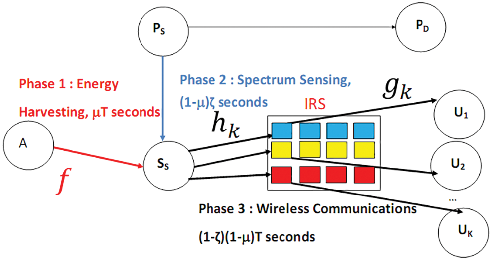
Figure 1: Network model
2.2 Energy Harvesting Without IRS
The harvested energy is given by
where β is an efficiency coefficient, PA = EA/Ts is the power of A, Ts is the symbol duration, f is channel gain from A to SS, L0 = T/Ts. We can write E(|f|2) = 1/dASSple where dXY is the distance from X to Y and ple is the path loss exponent.
The symbol energy of SS is computed as:
In Fig. 1, the users are ranked as follows: U1 is the strong user, Ui is the i-th strong user and UK is the weak user. The transmitted NOMA symbol by SS is equal to
si is the symbol of user Ui and 0 < POi < 1 is the power allocated to Ui such that 0 < PO1 < PO2 < ⋯< POK < 1 and
Let hp be the channel from SS to p-th IRS reflector. Let gp be the channel from p-th IRS reflector to Ui. Ii is a set of reflectors associated to Ui and contains Mi = |Ii| reflectors. We have: E(|hp|2) = 1/dSSIRSple. Furthermore, we have E(|gp|2) = 1/dIRSUiple.
We have hp = apexp(−jbp) where ap = |hp|. E(aq) = Γ(m + 0.5)/[Γ(m)
The phase of p-th reflector is equal to [1]
The received signal at Ui is given by
where ni is a Gaussian r.v. of variance N0.
Eq. (3) gives
where
In (6), we notice that the phase shifts of reflectors given in (4) have been chosen so that all reflections have a zero phase at user Ui.
Using (2), we deduce
Fi follows a Gaussian distribution with mean mFi = Mi Γ(m + 0.5)2/[Γ(m)2dSSIRSple/2dIRSUiple/2] and variance σFi2 = M/[dSSIRSpledIRSUiple][1−Γ(m + 0.5)4/Mi2/Γ(m)4]. Therefore, Fi2 has a non-central-chisquare distribution with degree of freedom one. For Rayleigh channels, |f|2 has also a central-chisquare distribution with degrees of freedom 2 m. Therefore, Yi is the product of a non-central and a central chisquare random variables and we have [31]
where Gn,mp,l(x) is the Meijer G-function.
We deduce
2.3 Signal to Interference Plus Noise Ratio (SINR) and Throughput Analysis
Ui performs Successive Interference Cancelation (SIC) and detects first sK since POK > POi. The corresponding SINR is
The contribution of the detected symbol sK is removed and Ui estimates sK−1 with the following SINR
The process is continued by detecting sl with SINR
The probability of an outage event at Ui is computed as
where PYi(y) is provided in (10). In Eq. (15)
The Packet Error Probability (PEP) at Ui is equal to [32]
where T0 is defined as [12]
where PL is packet length.
The total throughput is equal to
where Pf is the probability of a false alarm
where T1 is the energy detector threshold
The powers of NOMA users, sensing and harvesting durations μ and ζ are optimized as follows:
3 IRS to Enhance the Energy Harvesting Process
Fig. 2 shows that data transmission can use two IRS. IRS1 contains P reflectors between A to SS to enhance the energy harvesting process. IRS2 is between SS and users Ui with Mi reflectors to improve the throughput.
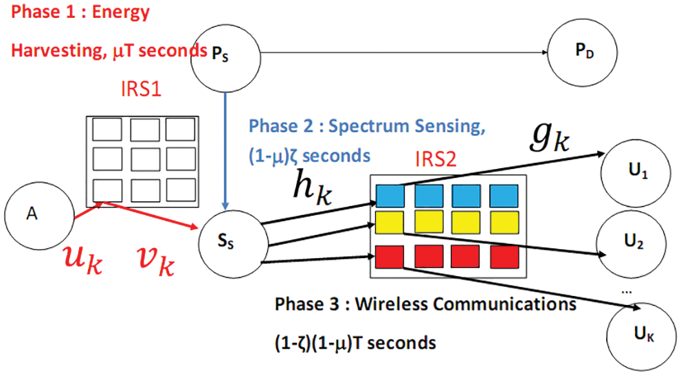
Figure 2: IRS used in energy harvesting
3.2 Energy Harvesting Using IRS
When energy harvesting uses IRS, we have
where
where δp = |up|, up is the channel from A to p-th IRS1 reflector and ηp = |vp|, vp is the channel from p-th reflector of IRS1 to SS.
The mean and variance of C are equal to
We deduce
The variable Yi should be replaced by Zi written as
where Fi is defined in (8).
Zi is the product of two non central chisquare r.v. Therefore, we have [31]
Fig. 3 depicts the total throughput for K = 2 users, QPSK modulation, m-fading figure m = 2, β = 0.5, T1 = 1, dASS = 1.1, dSSIRS = 1.2, dIRSU1 = 1.1, dIRSU2 = 1.5 and ple = 3. We notice that the use of M = Mi = 512, 256, 128, 64, 32, 16, 8 reflectors per user offers 45, 42, 39, 36, 33, 30, 27 dB gain vs. the absence of IRS [29]. Fig. 3 corresponds to optimal POi, μ and ζ.
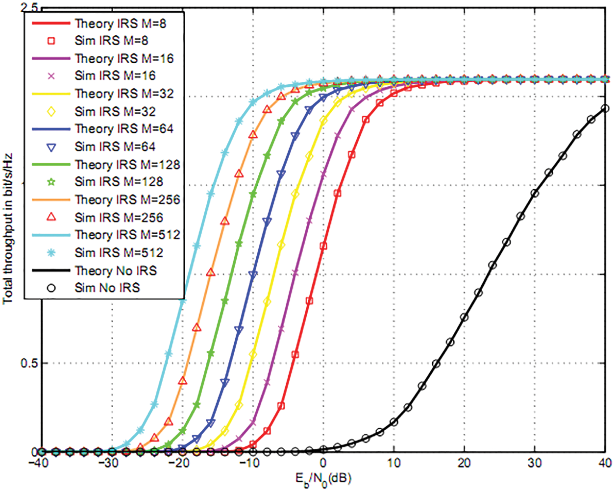
Figure 3: Total throughput for two users and QPSK
Figs. 4 and 5 compares the total throughput for M = Mi = 8, 16 with optimal μ and ζ to (μ = 1/3, ζ = 1/2). We observe that optimal harvesting and sensing duration μ and ζ offers a better throughput than (μ = 1/3, ζ = 1/2), (μ = 1/3, optimal ζ) and (optimal μ, ζ = 1/2).
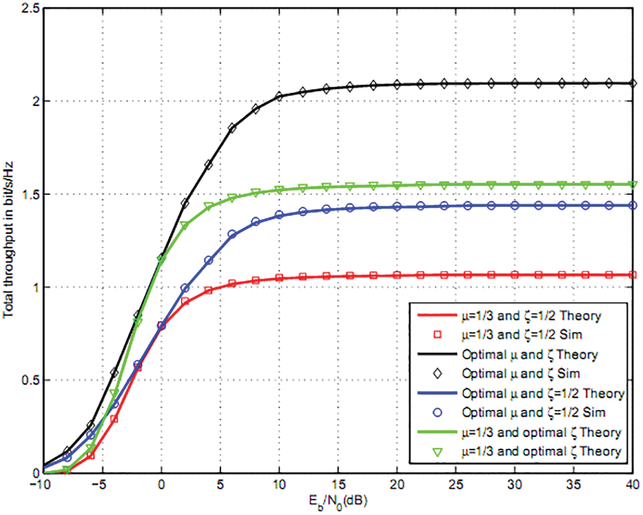
Figure 4: Total throughput for two users QPSK and M = 8
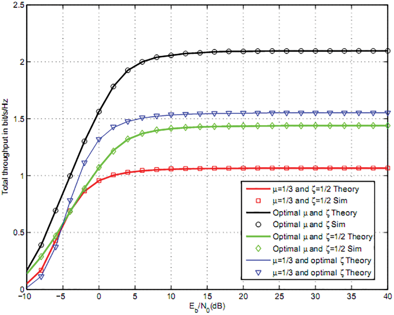
Figure 5: Total throughput for two users, QPSK and M = 16
Fig. 6 shows the total throughput for K = 3 users and 16QAM modulation, m-fading figure m = 2, T1 = 1, d = 1, dSSIRS = 1.2, dIRSU1 = 1.1, dIRSU2 = 1.3, dIRSU3 = 1.5. M = Mi = 512, 256, 128, 64, 32, 16, 8 reflectors per user offers 47, 44, 41, 38, 35, 32, 29 dB gain vs. NOMA without IRS [29]. In Fig. 6, we used an optimal powers as well as optimal μ and ζ.
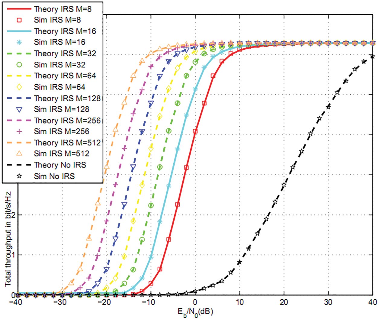
Figure 6: Total throughput for three users and 16QAM
Fig. 7 depicts the throughput for M = Mi = 16 reflectors per user. We optimized NOMA powers in Fig. 7. We observe that optimal sensing and harvesting durations ζ and μ offers a better throughput than (μ = 1/3, ζ = 1/2), (μ = 1/3, optimal ζ) and (optimal μ, ζ = 1/2).
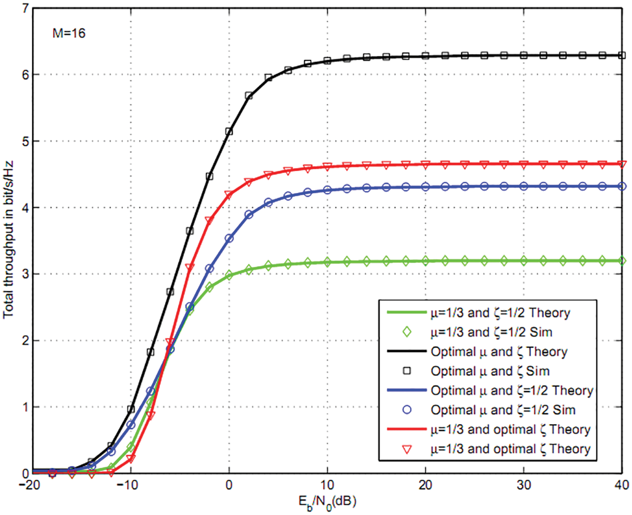
Figure 7: Total throughput for three users, 16QAM and M = 16
Fig. 8 shows the total throughput for the same parameters as Fig. 6. We have studied the effect of m-fading figure. For m = 3, we observe up to 8 and 2 dB gain vs. m = 1 and m = 2 that corresponds to Rayleigh channels.
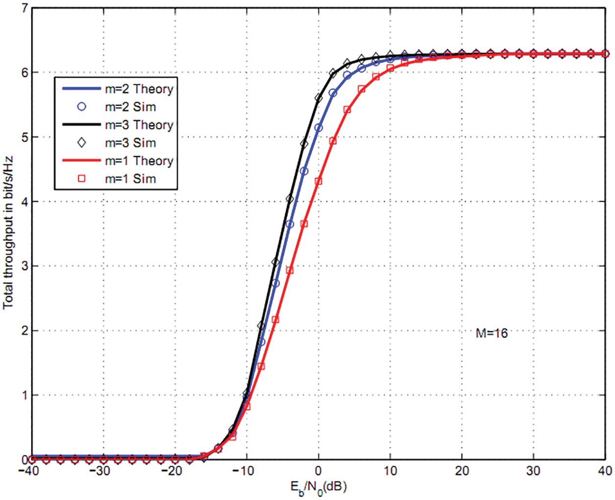
Figure 8: Total throughput for three users, 16QAM and M = 16
In Fig. 9, we plotted the total throughput for K = 3 users and 16QAM modulation. The parameters are the same as Fig. 6. We have plotted the throughput when a energy harvesting uses IRS. The parameters are dAIRS1 = 1.1 and dIRS1SS = 1.3. The use P = 8 reflectors for energy harvesting and M = Mi = 8 reflectors per user for data communications offers 7 and 38 dB gain vs. one IRS M = Mi = 8 and without IRS [29]. The use of P = 16 reflectors for energy harvesting and M = Mi = 8 reflectors per user for data communications offers 9 and 42 dB gain vs. one IRS M = Mi = 8 and without IRS [29].
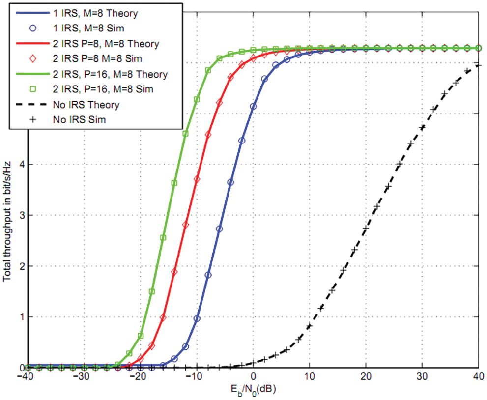
Figure 9: Total throughput using two IRS: three users, 16QAM
In this article, we optimized the powers of NOMA users, sensing and harvesting duration for CRN. Secondary source senses the channel over (1−μ)ζT s to detect primary activity. If no activity is detected, SS broadcasts a signal during (1−μ)(1−ζ)T s to NOMA users. The signal is reflected by Intelligent Reflecting Surfaces (IRS) towards K users. A set Ii of reflectors is associated to user Ui. The use of M = Mi = 512, 256, 128, 64, 32, 16, 8 reflectors per user offers 45, 42, 39, 36, 33, 30, 27 dB gain vs. wireless systems without IRS [29]. We also suggest the use of IRS in energy harvesting. The use P = 8 reflectors for energy harvesting and M = Mi = 8 reflectors per user for data communications offers 7 and 38 dB gain vs. one IRS M = Mi = 8 and without IRS [29]. The use of P = 16 reflectors for energy harvesting and M = Mi = 8 reflectors per user for data communications offers 9 and 42 dB gain vs. one IRS M = Mi = 8 and without IRS [29].
Funding Statement: The authors received no specific funding for this study.
Conflicts of Interest: The authors declare that they have no conflicts of interest to report regarding the present study.
References
1. E. Basar, M. Renzo, J. Rosny, M. Debbah, M. S. Alouini et al., “Wireless communications through reconfigurable intelligent surfaces,” IEEE Access, vol. 7, no. 2, pp. 116753–116773, 2019. [Google Scholar]
2. H. Zhang, B. Di, L. Song and Z. Han, “Reconfigurable intelligent surfaces assisted communications with limited phase shifts: How many phase shifts are enough?,” IEEE Transactions on Vehicular Technology, vol. 69, no. 4, pp. 4498–4502, 2020. [Google Scholar]
3. M. Renzo, “6G wireless: Wireless networks empowered by reconfigurable intelligent surfaces,” in 25th Asia-Pacific Conf. on Communications (APCC), vol. 1, no. 1, pp. 12–13, 2019. [Google Scholar]
4. E. Basar, “Reconfigurable intelligent surface-based index modulation: A new beyond MIMO paradigm for 6G,” IEEE Transactions on Communications, vol. 68, no.5, pp. 3187–3196, 2020. [Google Scholar]
5. Q. Wu and R. Zhang, “Towards smart and reconfigurable environment: Intelligent reflecting surface aided wireless network,” IEEE Communications Magazine, vol. 58, no. 1, pp. 106–112, 2020. [Google Scholar]
6. C. Huang, A. Zappone, G. Alexandropoulos, M. Debbah and C. Yuen, “Reconfigurable intelligent surfaces for energy efficiency in wireless communication,” IEEE Transactions on Wireless Communications, vol. 18, no. 8, pp. 4157–4170, 2019. [Google Scholar]
7. G. C. Alexandropoulos and E. Vlachos, “A hardware architecture for reconfigurable intelligent surfaces with minimal active elements for explicit channel estimation,” in ICASSP 2020-2020 IEEE Int. Conf. on Acoustics, Speech and Signal Processing (ICASSP), vol. 1, no.1, pp. 9175–9179, 2020. [Google Scholar]
8. H. Guo, Y. Liang, J. Chen and E. Larsson, “Weighted sum-rate maximization for reconfigurable intelligent surface aided wireless networks,” IEEE Transactions on Wireless Communications, vol. 19, no. 5, pp. 3064–3076, 2020. [Google Scholar]
9. V. Thirumavalavan and T. Jayaraman, “BER analysis of reconfigurable intelligent surface assisted downlink power domain NOMA system,” in 2020 Int. Conf. on COMmunication Systems and NETworkS (COMSNETS), vol. 1, no. 2, pp. 519–522, 2020. [Google Scholar]
10. C. Pradhan, A. Li, L. Song, B. Vucetic and Y. Li, “Hybrid precoding design for reconfigurable intelligent surface aided mmwave communication systems,” IEEE Wireless Communications Letters, vol. 9, no. 7, pp. 1041–1045, 2020. [Google Scholar]
11. K. Ying, Z. Gao, S. Lyu, Y. Wu, H. Wang et al., “GMD-Based hybrid beamforming for large reconfigurable intelligent surface assisted millimeter-wave massive MIMO,” IEEE Access, vol. 8, no. 2, pp. 19530–19539, 2020. [Google Scholar]
12. L. Yang, W. Guo and I. Ansari, “Mixed dual-hop FSO-RF communication systems through reconfigurable intelligent surface,” IEEE Communications Letters, vol. 24, no. 7, pp. 1558–1562, 2020. [Google Scholar]
13. B. Di, H. Zhang, L. Li, L. Song, Y. Li et al., “Practical hybrid beamforming with finite-resolution phase shifters for reconfigurable intelligent surface based multi-user communications,” IEEE Transactions on Vehicular Technology, vol. 69, no. 4, pp. 4565–4570, 2020. [Google Scholar]
14. Q. Nadeem, A. Kammoun, A. Chaaban, M. Debbah and M. Alouini, “Asymptotic max-min SINR analysis of reconfigurable intelligent surface assisted MISO systems,” IEEE Transactions on Wireless Communications, vol. 19, no. 12, pp. 7748–7764, 2020. [Google Scholar]
15. W. Zhao, G. Wang, S. Atapattu, T. Tsiftsis and C. Tellambura, “Is backscatter link stronger than direct link in reconfigurable intelligent surface-assisted system?” IEEE Communications Letters, vol. 24, no. 6, pp. 1342–1346, 2020. [Google Scholar]
16. S. Li, B. Duo, X. Yuan, Y. Liang and M. Renzo, “Reconfigurable intelligent surface assisted UAV communication: Joint trajectory design and passive beamforming,” IEEE Wireless Communications Letters, vol. 9, no. 5, pp. 716–720, 2020. [Google Scholar]
17. L. Dai, B. Wang, M. Wang, X. Yang, J. Tan et al., “Reconfigurable intelligent surface-based wireless communications: Antenna design, prototyping and experimental results,” IEEE Access, vol. 8, no. 3, pp. 45913–45923, 2020. [Google Scholar]
18. S. Hua and Y. Shi, “Reconfigurable intelligent surface for green edge inference in machine learning,” in 2019 IEEE Globecom Workshops (GC Wkshps), vol. 2, no. 3, pp. 10–15, 2019. [Google Scholar]
19. C. Huang, G. Alexandropoulos, C. Yuen and M. Debbah, “Indoor signal focusing with deep learning designed reconfigurable intelligent surfaces,” in IEEE 20th Int. Workshop on Signal Processing Advances in Wireless Communications (SPAWC), vol. 3, no. 4, pp. 11–14, 2019. [Google Scholar]
20. B. Yin, S. W. Zhou, S. W. Zhang, K. Gu and F. Yu, “On efficient processing of continuous reverse skyline queries in wireless sensor networks,” KSII Transactions on Internet and Information Systems, vol. 11, no. 4, pp. 1931–1953, 2017. [Google Scholar]
21. J. M. Zhang, K. Yang, L. Y. Xiang, Y. S. Luo, B. Xiong et al., “A Self-adaptive regression-based multivariate data compression scheme with error bound in wireless sensor networks,” International Journal of Distributed Sensor Networks, vol. 9, no. 3, pp. 913497, 2013. [Google Scholar]
22. J. Wang, C. Ju, Y. Gao, A. K. Sangaiah and G. J. Kim, “A PSO based energy efficient coverage control algorithm for wireless sensor networks,” Computers Materials & Continua, vol. 56, no. 3, pp. 433–446, 2018. [Google Scholar]
23. J. Wang, X. J. Gu, W. Liu, A. K. Sangaiah and H. J. Kim, “An empower hamilton loop based data collection algorithm with mobile agent for WSNs,” Human-centric Computing and Information Sciences, vol. 9, no. 1, pp. 1–14, 2019. [Google Scholar]
24. J. Wang, Y. Gao, C. Zhou, S. Sherratt and L. Wang, “Optimal coverage multi-path scheduling scheme with multiple mobile sinks for WSNs,” Computers, Materials & Continua, vol. 62, no. 2, pp. 695–711, 2020. [Google Scholar]
25. J. Wang, Y. Gao, W. Liu, W. Wu and S. J. Lim, “An asynchronous clustering and mobile data gathering schema based on timer mechanism in wireless sensor networks,” Computers Materials & Continua, vol. 58, no. 3, pp. 711–725, 2019. [Google Scholar]
26. J. Wang, Y. Gao, X. Yin, F. Li and H. J. Kim, “An enhanced PEGASIS algorithm with mobile sink support for wireless sensor networks,” Wireless Communications and Mobile Computing, 2018, https://doi.org/10.1155/2018/9472075. [Google Scholar]
27. Q. Tang, K. Yang, P. Li, J. M. Zhang, Y. S. Luo et al., “An energy efficient MCDS construction algorithm for wireless sensor networks,” EURASIP Journal on Wireless Communications and Networking, 2012, https://doi.org/10.1186/1687-1499-2012-83. [Google Scholar]
28. Z. Liao, J. Wang, S. Zhang, J. Cao and G. Min, “Minimizing movement for target coverage and network connectivity in mobile sensor networks,” IEEE Transactions on Parallel and Distributed Systems, vol. 26, no. 7, pp. 1971–1983, 2014. [Google Scholar]
29. R. Alhamad and H. Boujemaa, “Optimal harvesting and sensing durations for cognitive radio networks,” Signal Image Video Process, vol. 14, no. 7, pp. 1397–1404, 2020. [Google Scholar]
30. J. Proakis, “Digital communications,” Mac Graw-Hill, 5th edition, 1221 Aveue of the Americas, New York, NY 10020, 2007. [Google Scholar]
31. W. Wells, R. Anderson and J. Cell, “The distribution of the product of two central or non-central chi-square variates,” The Annals of Mathematical Statistics, vol. 33, no. 3, pp. 1016–1020, 1962. [Google Scholar]
32. X. Burr, A. Wei, J. Ben and D. Grace, “A general upper bound to evaluate packet error rate over quasi-static fading channels,” IEEE Trans. Wireless Communications, vol. 10, no. 5, pp. 1373–1377, 2011. [Google Scholar]
 | This work is licensed under a Creative Commons Attribution 4.0 International License, which permits unrestricted use, distribution, and reproduction in any medium, provided the original work is properly cited. |