| Computers, Materials & Continua DOI:10.32604/cmc.2022.031042 | |
| Article |
Crack Propagation in Pipelines Under Extreme Conditions of Near-Neutral PH SCC
Mechanical Engineering Department, College of Engineering, Abu Dhabi University, Abu Dhabi, 59911, United Arab Emirates
*Corresponding Author: Abdullah Alsit. Email: 1062242@students.adu.ac.ae
Received: 08 April 2022; Accepted: 31 May 2022
Abstract: Stress Corrosion Cracking (SCC) process through which cracks occur in a variety of susceptible materials is a result of a combination of residual or applied stresses and corrosion. In oil and gas field, buried pipeline steels are made of low-alloy steels with a ferritic-pearlitic structure, such as X70. In dilute solutions, these materials are prone to SCC failure. The Near-neutral simulated soil solution (NS4) solution is established to imitate SCC conditions and subsequently became the industry requirement for crack growth experiments in the majority of laboratories. The strain-assisted active crack pathways are considered while modelling SCC growth as an oxide film rupture and anodic dissolution process. It’s been hypothesized that increasing the strain concentration can help with dissolution at the film-free crack tip. This research focuses on estimating the SCC crack growth rate under various environmental conditions in oil and gas pipelines using finite element modelling. The simulation is carried out using the J-integral theory in the COMSOL Multiphysics program. Simulations are performed to model the crack growth rate (CGR) using slip anodic dissolution (film rupture) mechanism. The plastic strain gradient is required to compute the SCC CGR (da/dt). Because the plastic strain located at crack tip increases proportionally to the crack length as it propagates, the CGR increases as the stress intensity factor (SIF) increases. The crack growth rates increase when constant loads are applied and as the temperature rises, and elevating the cathodic potential has a minimal influence on the propagation rate of cracks but raises the material yield strength and imparts brittle behavior to it.
Keywords: Stress corrosion cracking SCC; oxide film rupture and anodic dissolution; crack growth rate CGR; J-integral; stress intensity factor SIF
In stress corrosion cracking, cracking occurs due to a combination of applied or residual stresses and corrosion in a variety of susceptible materials. SCC has the potential to cause catastrophic failure in a large variation of engineering components and applications, including petrochemical pipelines and mechanical components operating in submerged environments [1,2]. External SCC requires three criteria to develop on subterranean pipelines: (1) a significant magnitude of applied stress, (2) a susceptible material, (3) and a corrosive environment near the metal surface [3]. Environmentally assisted cracking (EAC) refers to a variety of mechanisms that contribute to this phenomenon. SCC, hydrogen-induced cracking as well as corrosion fatigue are the primary types of EAC. The three structures tend to be very similar in nature regardless of some fundamental differences [4]. According to the pipe cracks failure studies, several experts determined that increased soil mobility appeared essential for coating rupture and cracking to occur at a buried pipeline [5]. API-specified low-alloy steels, such as X70, having a ferritic-pearlitic microstructure are utilized in the oil and gas industry’s buried pipeline steels. Transgranular stress corrosion cracking (TGSCC) can occur in certain materials when they are exposed to diluted solutions [6]. To imitate SCC environments, the NS4 solution was developed, and it eventually became the accepted standard condition for CGR experiments in the majority of laboratories [7]. The strain rate correlated with applied stress is important in stress corrosion cracking. If the fracture propagation mechanism incorporates strain rate, a relationship should exist between the strain rates on the crack tip and the crack propagation rates [8]. This study uses finite element modeling by employing the slip dissolution/film rupture mechanism to estimate the SCC crack growth rate in oil and gas pipelines under various environmental conditions in the Gulf region.
In EAC, the hydrogen-induced cracking (HIC) or slip-dissolution processes have often been deemed constructed based hypotheses [9]. There are common prevalent crack-initiation sites for SCC such as fatigue crack, coating defect, intergranular crack, and slip-band dissolution [10]. Keeping the crack tip at initial surface state at high strain rates, the crack propagation may be atomistically detected by measuring the dissolution or hydrogen evolution rate of a reaction on the film surface. However, the fracture tip surface does not always remain exposed under normal strain rate conditions. The rate of oxide rupture, dissolution rate, and the rate of fluid diffusion at or close the crack tip all have an influence on crack propagation [11]. It has been challenging to discern between these two processes mechanistically because these rate-determining factors may control simultaneous hydrogen-induced cracking and slip-dissolution mechanisms. As a consequence, several researchers have opted to work with the Anodic-dissolution model, while others have selected the HIC model [12]. According to Raja and Shoji, Crack growth can be caused by only four different atomistic processes. These are the following, (a) Atoms are removed from crack tips and dissolved in solution. (b) Atomic shear movement at crack tips may take the form of dislocation emission or dislocation egress (opposite sign) at crack points. (c) Decohesion (Tensile atom separation at crack tips), which may entail atom shear movement in its early stages. (d) Atomic diffusion on the surface of crack tips. The following three methods are not dependent on the occurrence of an environment, but they can be facilitated by it [13].
1.2 Slip Dissolution/Film Rupture Mechanism
The film rupture/anodic dissolution approach, sometimes described to as the slip-dissolution mechanism, grown from a number of theories that explored strain-assisted active crack patterns. The strain concentration has been proposed as a method of enhancing dissolving at the film-free fracture tip. Crack propagating arises because of oxide rupture at the crack tip due to increased strain in the surrounding matrix or as a result of the appearance of slip steps in the slip-dissolution model [14]. Fig. 1 illustrates the slip-dissolution mechanism for SCC, which involves localized slip rupturing oxide films at crack tips, followed by repassivation behind crack tips.
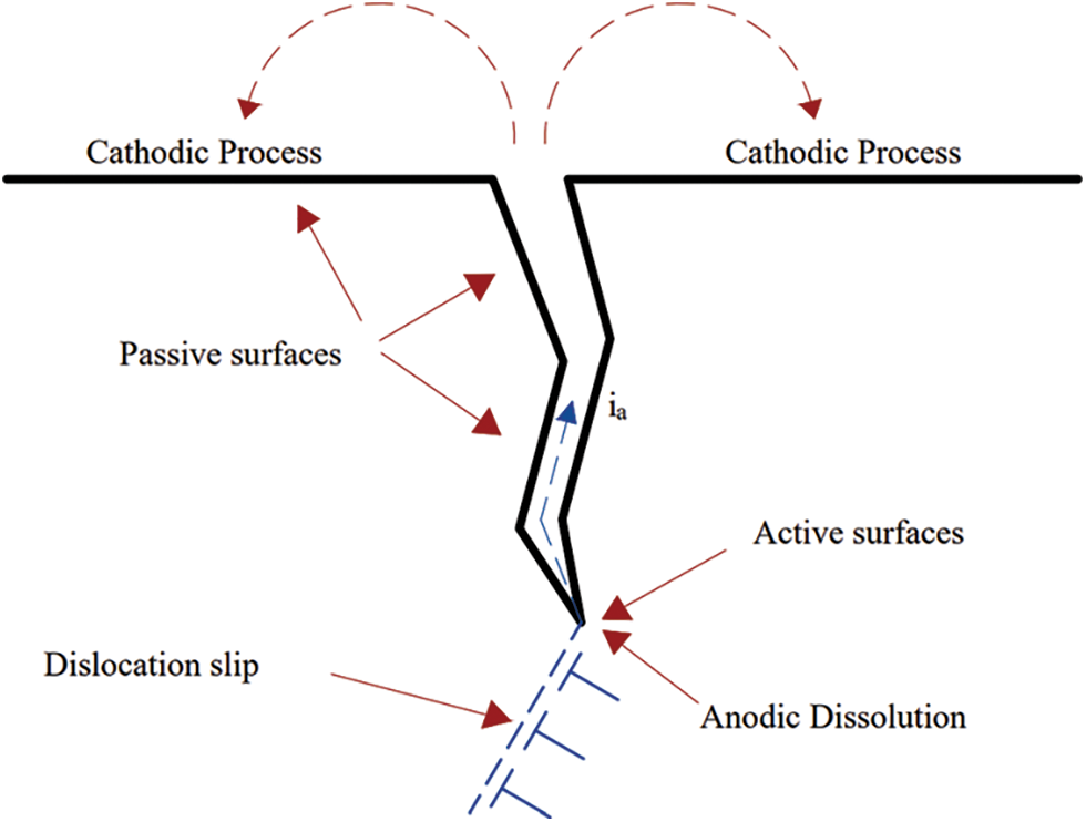
Figure 1: SCC anodic/slip dissolution mechanism represented as rupture of oxide films on crack tips caused by localized slip
SCC growth, according to Ford [15], can be modeled as a process involving anodic dissolution and oxide film rupture. This method results in the formation of an oxide layer on the exposed metal surface near the crack tip. This layer then fractures the bulk’s grain boundaries. The crack advances as a consequence of the grain boundary dissolution. The metal is oxidized, followed by passivation, and the process is repeated until the oxide ruptures. The formula of the SCC growth rate under slip dissolution condition can be expressed by Faraday’s Law [16]:
where da/dt indicates the rate of SCC crack propagation in millimeters per second, M and indicate the density and atomic weight of the metal, respectively, Z indicates the charge change caused by the oxidation development, F represents Faraday’s number, and I is the oxidation current density. According to [17] Eq. (1), the F-A model can be written as the following;
where ka is the oxidation rate,
where i0: oxidation current density, t0: time prior to the current decays, and
Due to the difficulty of determining the strain rate near the tip, the strain,
When the tip is positioned at the characteristic length r0 at the vicinity of the crack tip, the change in tensile plastic strain along with crack propagation is represented by the expression
where;
Elastic plastic finite element method (EPFEM) gives a practical method to determine
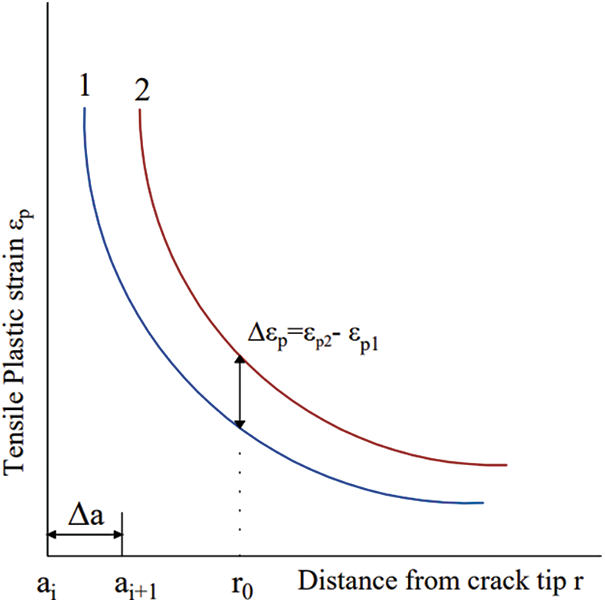
Figure 2: A theoretical foundation for numerically calculating the propagation of SCC cracks
As shown in Fig. 2, when the crack propagation from ai to ai + 1, the plastic strains
After substituting
Elastoplastic and elastic analyses can both benefit from the use of the J-integral technique. The value of the J-integral in the case of elasticity may be proven to be corresponding to the strain energy release rate (G) and associated to the stress intensity factor (K) [22]. In [23] the j-integral in two dimensional (2D) is represented in Eq. (9);
where Ws is the density of the strain energy, σ represents the stress tensor, and m indicates the external normal of the integration contour Γ. For the purposes of Eq. (9), the crack is assumed to be growing in the positive x-axis, and integration is done over Γtot = Γ U Γface, which might be any closed route around the crack tip (see Fig. 3) [24].
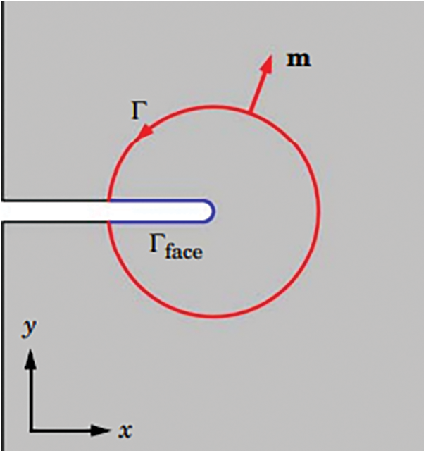
Figure 3: Circular J-integral positioned around a notch in 2D [24]
The stress intensity factor KI Crack opening, or mode I may be calculated using the J-integral [25]. According to Sahli et al. [26] the following decomposition of the J-integral is applied to determine the stress intensity factor in 2D;
where Eeff is an functional Young’s modulus that reflects the crack front’s stress condition, and β is the coefficient that accounts for the mode mixture.
During the corrosion process the electrons are liberated Because of metal dissolution on the anodic site. These electrons are sent to the cathode, which reduces oxygenized water to hydrogen ions. During metal corrosion, the following reactions take place [27,28].
The local surface concentrations of reactive species and the local electrode potential determine the kinetics of electrochemical reactions. Except at the tip, where the kinetics are contingent on the oxide film rupture frequency and the local electrode potential, it is assumed that a constant anodic passive current density, ip, flows everywhere across the interface [29].
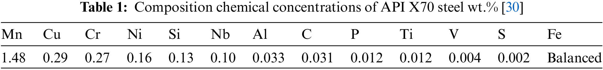
The API 5L X70 and X60 steel are employed in the oil and gas pipeline sector due to their high strength-to-weight ratio, high fracture toughness, and most importantly, their high yield strength. API X70 chemical composition are in Tab. 1 [30].
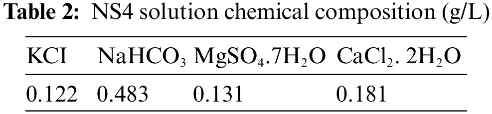
In all of the electrochemical studies, the corrosive environment was a virtual soil solution (named NS4) with a pH equals to three [31]. A common method for simulating soil solution for the test of near-neutral pH-SCC behavior has been to use a synthetic solution of NS4 to simulate soil solution. Similar research has used a variety of synthetic soil solutions, including NS1, NS2, NS3, and NS4 among others [32]. Tab. 2 depicts the NS4 solution’s chemical structure that was applied in this experiment [33].
The Elastic Properties of the API X70 steel under soil Solution (NS4) are indicated in Tab. 3 [34]. The Plastic Properties are shown in Fig. 4, Experimenting on the “Slow Strain Rate Stress Corrosion Testing Machine” yields the tensile true stress-strain curve.
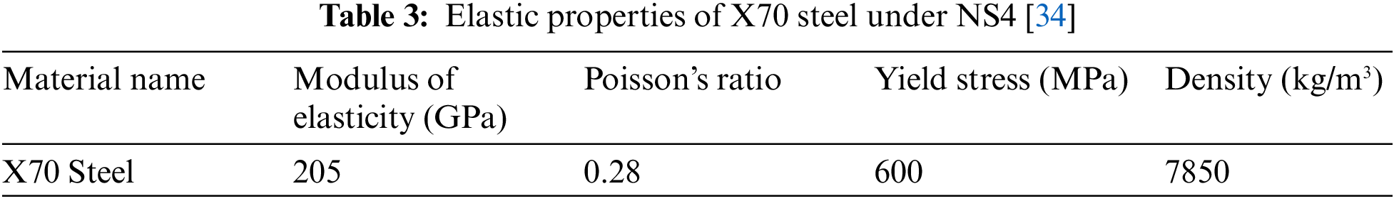
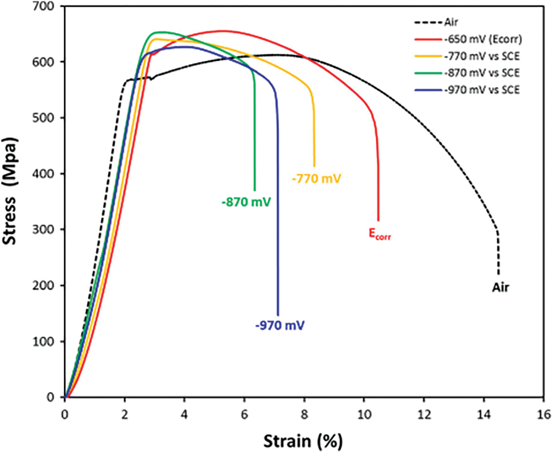
Figure 4: The stress-strain curves (σ vs. ε) of API X70 steel submerged in NS4 solution when various cathodic potentials are applied [35]
To determine the mechanical characteristics of the X70 steel in a soil environment (NS4), Slow strain rate test (SSRT) was done on smooth cylindrical tensile specimens in air and a synthetic soil solution at an applied strain rate equals to 10−6 1/s (NS4 solution) using a Mobile Constant Extension Rate Tests (MCERT) machine. Cathodic potential may have an effect on the mechanism of SCC cracking and on the susceptibility of steels to SCC, as it alters the concentration of hydrogen in the solution. According to Galván-martínez SCC tests with SSRT were conducted at corrosion potential equals to −0.650 V vs. SCE and at three various cathodic potentials (−770 mV, −870 mV and −970 mV) measured by electrochemical impedance spectroscopy (EIS) and compared to the saturated calomel electrode as indicated in Fig. 4 the stress-strain curve [35].
The Ramberg–Osgood relationship can be used to express the real stress-strain curve of API X70 steel. The Ramberg-Osgood model describes the nonlinear behavior of a steel pipeline.
where σ0 indicates the material’s yield strength, ε0 represents the material’s yield strain, respectively, α is the material’s yield offset coefficient, and the material’s exponent of the strain hardening is represented as n [36].
3 SCC Crack Growth FEM and Simulation
The simulation was done using COMSOL Multiphysics® (solid mechanics model) software [37]. A plane stress plate with an area of 0.1 m by 0.050 m including an initial crack varying between 5 to 20 mm as shown in Fig. 5, symmetry boundary condition assumed to simplify the model. An applied three different tensile constant loading on the top boundary 150, 200, 250 MPa.
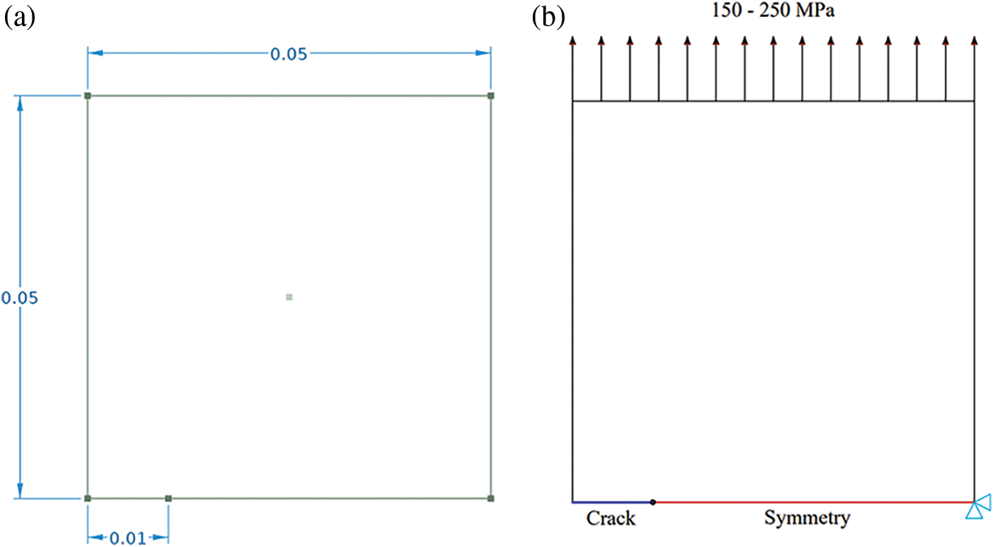
Figure 5: a) Geometry model of the plate, in m, and b) Boundary conditions
The crack is defined in COMSOL as 3 j-integral contours. The first few contours may be erroneous if the first contour integral is generated by defining the nodes at the crack tip. Additional contours are sought to evaluate the accuracy of these contours and estimate the value of the contour integral, which tends to be relatively constant from one contour to the next. So, the j-integral values after the third contour remain the same, and their size are depending on the crack size as shown in Fig. 6, where it can give the j-integral values for the three j-integral contours, and predict the crack growth direction. To overcome this pathological mesh sensitivity, one might impose the characteristic length of the damage region in the material’s calculation method. The characteristic length r is equal to 60 μm from the actual crack tip, which represents the elastic-plastic crack tip [38].
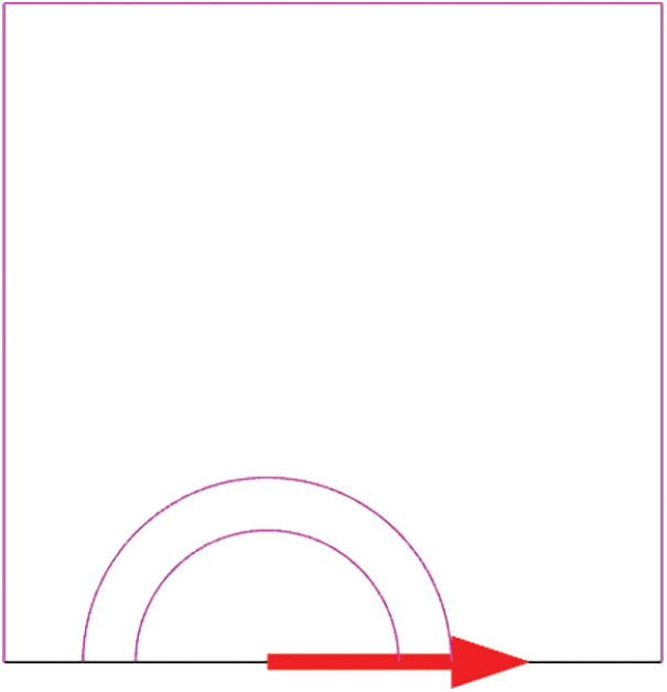
Figure 6: Crack contour integrals and predicted crack growth direction
Fig. 7, shows 2d tetrahedron mesh used mesh consisting of 2307 domain elements and 137 boundary elements, and refinement on the crack tip, the simulation run on a 4 cores device.
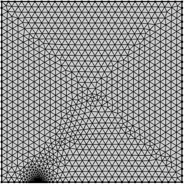
Figure 7: Meshing
To define the change in temperature a multiphysics analysis of the solid mechanics and heat transfer analysis is assumed to define the thermal properties and thermal boundary conditions, the values of the temperature are, 25oC, 50oC, 90oC. A stationary solver with parametric sweep analysis was done for different crack lengths from 10 to 15 mm, and a 0.1 mm difference at each run, this technique assumes the crack is propagating from 10--15 mm.
To obtain the SCC crack propagation rate (da/dt), the plastic strain gradient is required according to Eq. (6). The normal plastic strain
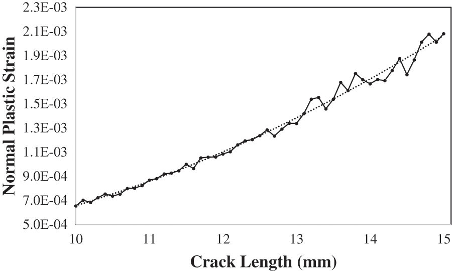
Figure 8: Normal plastic strain vs. crack length
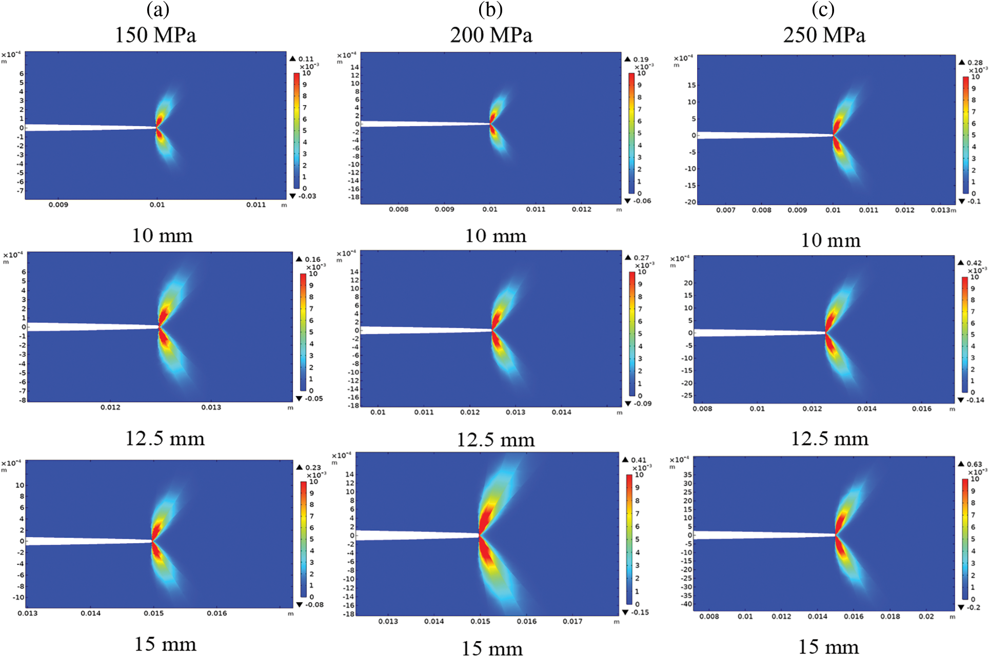
Figure 9: Normal plastic strain at the crack tip for different crack length 10, 12.5, 15 mm. a) 150 MPa. b) 200 MPa. c) 250 MPa
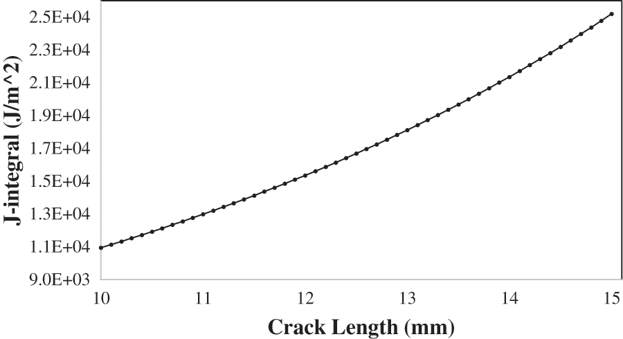
Figure 10: J-integral vs. crack length at 200 MPa and 25oC
4.2 SCC Crack Growth Rate (da/dt)
Eq. (6) is applied to compute the SCC growth rate (mm/sec). Tab. 4 shows the Standard electrode kinetic for X70 steel under soil Environment (NS4) [39]. Ka’ value is assumed to be
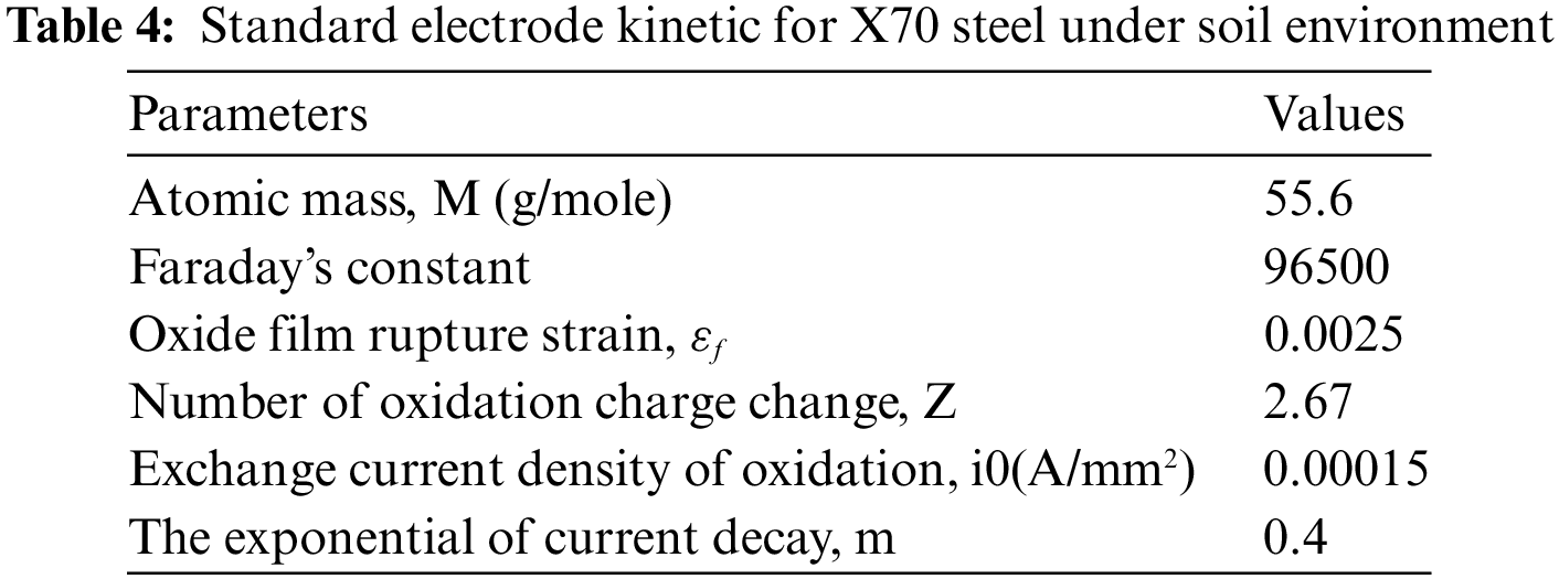
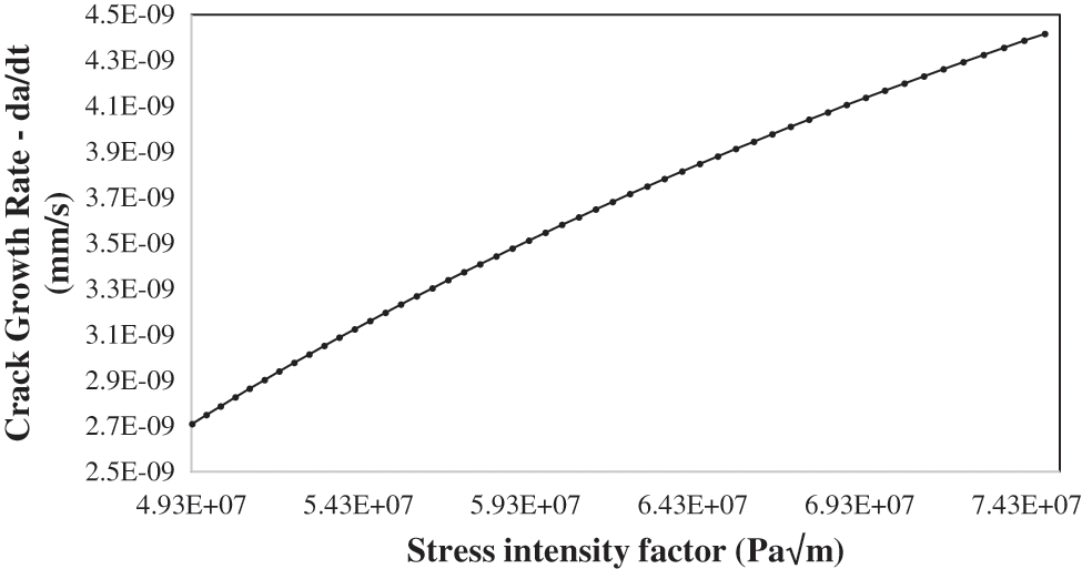
Figure 11: Crack growth rate CGR da/dt vs. stress intensity factor KI at 200 MPa and 25oC
Fig. 12 indicates the CGR vs. the crack size for various applied loads (150, 200, 250 MPa), at 25 C temperature, and the corrosion potential is −650 mV. The CGR is increasing linearly with the crack length as the normal plastic strain gradient raising with the crack length, owing to the dependence of the crack propagation rate on the normal plastic strain gradient. Moreover, it seems that the crack propagation rates are rising with the applied constant loads, since the 150 MPa has the least average of crack growth rate values which ranges between 2.1E-09 and 2.4E-09, and the 250 applied constant load has the highest and ranges between 2.7E-09 to 5.0E-09. The slope of the 150 MPa applied load is lower remarkably than the other applied load because the plasticity at 150 MPa has a significantly smaller effect than the other applied load. The initial CGR values of the 200 and 250 MPa are approximately equal, but as the crack is propagating the values diverge more.
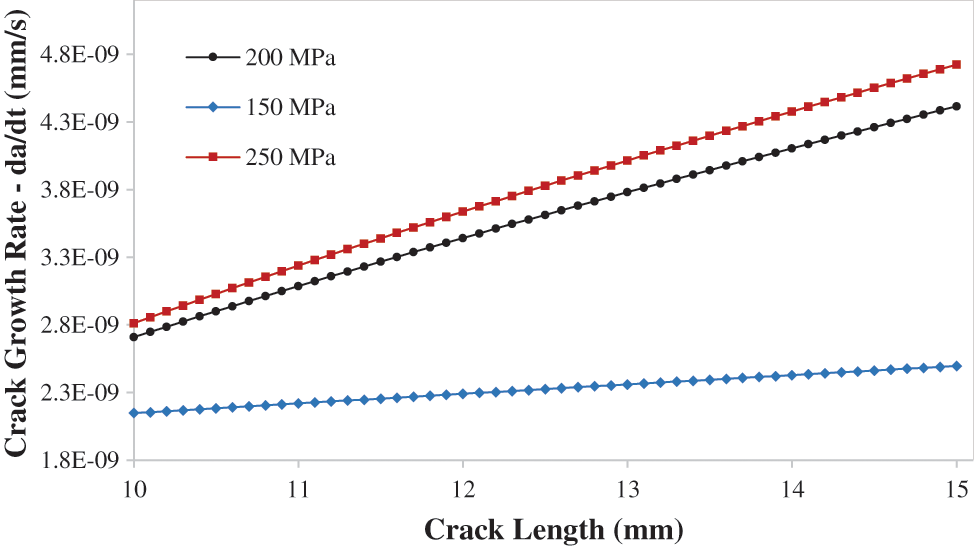
Figure 12: Crack growth rate da/dt vs. crack length at 25 oC for different applied constant loads 150, 200, and 250 MPa
4.3 Temperature Effect on SCC Crack Growth Rate da/dt at 200 MPa
The temperature in UAE is varying within the year, so it is important to consider the temperature as a factor that is affecting the SCC crack growth rate. The temperatures 25oC, 60oC, and 100oC are applied on the crack boundaries. Fig. 13 shows the CGR da/dt vs. crack length for various applied temperatures 25oC, 60oC, 100oC. It’s obvious from Fig. 13 that as the temperature is elevated the crack propagation rate average increases, due to the rise of the normal plastic strain with the temperatures. Furthermore, when increasing the temperature, the plasticity properties of the material effected and become more plastic. As crack growth rate increase from 2.1E-09 to 4.5E-09 at 60oC, and for 100oC the crack growth rate increase from 2.8E-09 to 5.0E-09. The crack growth rate was same initially for both temperatures 25oC and 60oC, but the difference has increase with the crack length increases.
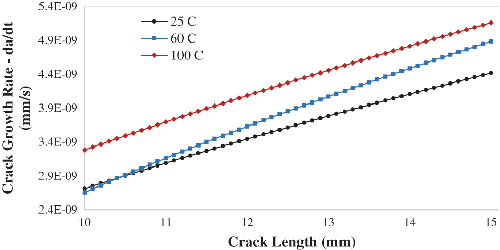
Figure 13: Crack growth rate da/dt vs. crack length for different applied temperature 25, 60, 100 C
4.4 Corrosion Potential Influence on SCC Crack Growth Rate da/dt at 200 MPa and 25 C
The corrosion potential values are taken from an experiment done by [34], the corrosion ensues when a specific value of the crack potential is achieved. The corrosion potential was −650 mV and then kept increasing the corrosion potential to analyze the influence on the stress-strain curves of the material. The corrosion potential used in this study is −650, −770, −870 mV. Fig. 14 indicates the Crack Growth rate da/dt vs. Crack length for various corrosion potential values and it ranges between 2.5E-09 and 4.2E-09. Raising the cathodic potential has minimal effect on the CGR, but it increases the yield strength of the material and gives it a brittle material behaviour [40].
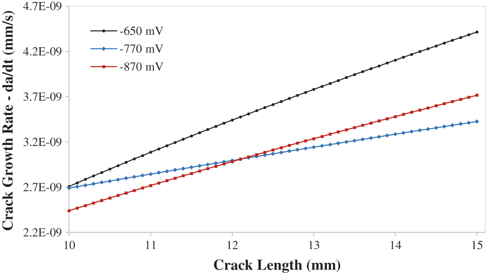
Figure 14: Crack growth rate da/dt vs. crack length for different cathodic potentials −650 corr, −770, −870 mV
While the current study examines only SCC crack growth under static loading, future work under dynamic loading, such as in slow strain rate testing SSRT, may be beneficial. Another possibility is to combine two distinct types of loading, such as static and fatigue, which will be the focus of future work.
This article proposes a new technique for modeling the crack growth rate and examining the various factors that affect it using COMSOL Multiphysics finite elements. The plastic strain gradient is required to calculate the rate of SCC crack growth da/dt. The normal plastic strain increases proportionally to the length of the crack; thus, as the crack propagates, it increases in length. The J-integral rises exponentially with the crack length. This J-integral result explains why the normal plastic strain increases in proportion to the length of the crack. The CGR increases as the SIF value increases. As a result, the growing rate of the crack increases as it propagates, as does the stress intensity factor. As constant loads are applied and the temperature rises, the crack growth rates accelerate. Raising the cathodic potential has a minimal influence on the rate of crack propagation, but it increases the yield strength and causes the material brittle. Both applied load and temperature have an approximately equal effect on the crack growth rate, with applied load having the greatest effect at lower values and temperature having the greatest effect at higher values.
Funding Statement: This work is supported by ASPIRE Award for Research Excellence (AARE 2019) under the Advanced Technology Research Council-ASPIRE through Project Number AARE19-098.
Conflicts of Interest: The authors declare that they have no conflicts of interest to report regarding the present study.
References
1. Y. F. Cheng, in Stress Corrosion Cracking of Pipelines, 1st ed., Hoboken: John Wiley & Sons, 2013. [Google Scholar]
2. A. H. Al-Moubaraki and I. B. Obot, “Corrosion challenges in petroleum refinery operations: Sources, mechanisms, mitigation, and future outlook,” Journal of Saudi Chemical Society, vol. 25, no. 12, pp. 101370, 2021. [Google Scholar]
3. S. Shipilov and F. King, “Pipeline stress corrosion cracking: Direction and control,” Materials Performance, vol. 54, no. 8, pp. 30–37, 2015. [Google Scholar]
4. P. Combrade, “Environmentally Assisted Cracking: Some Critical Aspects,” in Mechanics-Microstructure-Corrosion Coupling: Concepts, Experiments, Modeling, 1st ed., UK: Elsevier, pp. 1–22, 2019. [Google Scholar]
5. A. C. Liu, Z. Li, B. Zhao, Z. Liu, C. Du et al., “Stress corrosion mechanism and susceptibility of X80 steel under a disbonded coating in an acidic soil solution,” Journal of Materials Research and Technology, vol. 14, pp. 533–547, 2021, http://doi.org/10.1016/j.jmrt.2021.06.092. [Google Scholar]
6. A. Contreras, M. Salazar, A. Carmona and R. Galván-Martínez, “Electrochemical noise for detection of stress corrosion cracking of low carbon steel exposed to synthetic soil solution,” Materials Research, vol. 20, no. 5, pp. 1201–1210, 2017. [Google Scholar]
7. O. I. Zvirko, S. F. Savula, V. M. Tsependa, G. Gabetta and H. M. Nykyforchyn, “Stress corrosion cracking of gas pipeline steels of different strength,” Procedia Structural Integrity, vol. 2, pp. 509–516, 2016. http://doi.org/10.1016/j.prostr.2016.06.066. [Google Scholar]
8. W. Chen, “Modeling and prediction of stress corrosion cracking of pipeline steels,” in Trends in Oil and Gas Corrosion Research and Technologies: Production and Transmission, Cambridge, UK: Woodhead, pp. 707–748, 2017. http://doi.org/10.1016/B978-0-08-101105-8.00030-9. [Google Scholar]
9. R. I. Bogdanov, E. M. Gutman, I. V. Ryakhovskikh, Y. B. Unigovski and R. Z. Shneck, “Stress corrosion cracking of pipeline steels in near-neutral-pH solutions: The role of mechanochemical and chemomechanical effects,” AIMS Materials Science, vol. 6, no. 6, pp. 1065–1085, 2019. [Google Scholar]
10. S. Lynch, “Mechanistic and fractographic aspects of stress corrosion cracking,” Corrosion Reviews, vol. 30, no. 3–4,. pp. 63–104, 2012. [Google Scholar]
11. P. L. Andresen and F. Peter Ford, “Life prediction by mechanistic modeling and system monitoring of environmental cracking of iron and nickel alloys in aqueous systems,” Materials Science and Engineering, vol. 103, no. 1, pp. 167–184, 1988. [Google Scholar]
12. M. M. Hall, “Crack tip strain rate equation with applications to crack tip embrittlement and active path dissolution models of stress corrosion cracking,” Environment-Induced Cracking of Materials, vol. 1, pp. 59–68, 2008. http://doi.org/10.1016/B978-008044635-6.50008-X. [Google Scholar]
13. H. E. Hanninen, “Stress corrosion cracking,” Comprehensive Structural Integrity, Amsterdam, Elsevier, vol. 6, pp. 1–29, 2003. https://doi.org/10.1016/B0-08-043749-4/06133-4. [Google Scholar]
14. H. E. Hanninen, “Stress corrosion cracking,” Comprehensive Structural Integrity, vol. 6, pp. 1–29, 2003, https://doi.org/10.1016/B0-08-043749-4/06133-4. [Google Scholar]
15. F. P. Ford, “Mechanisms of environmentally-assisted cracking,” International Journal of Pressure Vessels and Piping, vol. 40, no. 5, pp. 343–362, 1989. [Google Scholar]
16. S. Gavrilov, M. Vankeerberghen, G. Nelissen and J. Deconinck, “Finite element calculation of crack propagation in type 304 stainless steel in diluted sulphuric acid solutions,” Corrosion Science, vol. 49, no. 3, pp. 980–999, 2007. [Google Scholar]
17. R. Bashir, H. Xue, J. Zhang, R. Gue, N. Hayat et al., “Effect of material macrostructural parameters on quantitative stress corrosion cracking plastic zone using extended finite element method in welded joints for light water reactor environment,” Corrosion, vol. 76, no. 9, pp. 826–834, 2020. [Google Scholar]
18. R. Bashir, H. Xue, J. Zhang, R. Gue, N. Hayat et al., “Effect of XFEM mesh density (mesh size) on stress intensity factors (Kstrain gradient (
19. H. Xue, Y. Sato and T. Shoji, “Quantitative estimation of the growth of environmentally assisted cracks at flaws in light water reactor components,” Journal of Pressure Vessel Technology, Transactions of the ASME, vol. 131, no. 1, pp. 1–9, 2009. [Google Scholar]
20. K. Zhao, H. Xue, F. Yang and L. Zhao, “Probability prediction of crack growth rate of environmentally assisted cracks of nickel-based alloys based on latin hypercube sampling,” International Journal of Pressure Vessels and Piping, vol. 172, pp. 391–396, 2019, http://doi.org/10.1016/j.ijpvp.2019.04.005. [Google Scholar]
21. Z. Li, Y. Lu and X. Wang, “Modeling of stress corrosion cracking growth rates for key structural materials of nuclear power plant,” Journal of Materials Science, vol. 55, no. 2, pp. 439–463, 2020. [Google Scholar]
22. K. Ohtsuka, “Generalized J-integral and its applications I∼basic theory,” Japan Journal of Industrial and Applied Mathematics, vol. 2, no. 2, pp. 329–350, 1985. [Google Scholar]
23. A. Frediani, “Experimental measurement of the J-integral,” Engineering Fracture Mechanics, vol. 19, no. 6, pp. 1105–1137, 1984. [Google Scholar]
24. Comsol Multiphysics, “The structural mechanics module user’s guide.” COMSOL AB, Stockholm, pp. 675–679, 2020. Accessed: Oct. 23, 2021. [Online]. Available: https://www.comsol.com. [Google Scholar]
25. C. L. Zhu, J. B. Li, G. Lin and H. Zhong, “Study on the relationship between stress intensity factor and J integral for mixed mode crack with arbitrary inclination based on SBFEM,” IOP Conference Series: Materials Science and Engineering, vol. 10, no. 1, pp. 1–10, 2014. [Google Scholar]
26. A. Sahli and O. Rahmani, “Stress intensity factor solutions for two-dimensional elastostatic problems by the hypersingular boundary integral equation,” Journal of Strain Analysis for Engineering Design, vol. 44, no. 4, pp. 235–247, 2009. [Google Scholar]
27. J. L. González-Velázquez, “Environmentally-assisted fracture,” in Structural Integrity, vol. 3, Cham, Switzerland: Springer, pp. 97–123, 2018. http://doi.org/10.1007/978-3-319-76651-5_5. [Google Scholar]
28. D. Gorse, “Stress corrosion cracking: An electrochemist point of view,” in Multiscale Phenomena in Plasticity: From Experiments to Phenomenology, Modelling and Materials Engineering, Netherland: Springer, pp. 425–440, 2000. http://doi.org/10.1007/978-94-011-4048-5_33. [Google Scholar]
29. S. Gavrilov, M. Vankeerberghen and J. Deconinck, “Finite element calculation of crack propagation in type 304 stainless steel in diluted sulphuric acid solution under stress corrosion conditions,” TMS (The Minerals, Metals Materials Society), vol. 1, pp. 117–124, 2005. [Google Scholar]
30. Z. Cui, L. Wang, Z. Liu, C. Du, X. Li et al., “Anodic dissolution behavior of the crack tip of X70 pipeline steel in near-neutral ph environment,” Journal of Materials Engineering and Performance, vol. 25, no. 12, pp. 5468–5476, 2016. [Google Scholar]
31. Z. Ahmad, in Principles of Corrosion Engineering and Corrosion Control, 1st ed., Oxford, UK: Butterworth-Heinemann, 2006. [Online]. Available: https://www.icheme.org. [Google Scholar]
32. M. B. Zamora, R. Galván-Martínez, A. Carmona, M. Baltazar, A. Contreras et al., “Stress corrosion cracking of X70 pipeline steel immersed in synthetic soil solution,” AFINIDAD, vol. 76, no. 585, pp. 52–62, 2019, [Online]. Available: https://www.researchgate.net/publication/346115287. [Google Scholar]
33. M. A. Mohtadi-Bonab, “Effects of different parameters on initiation and propagation of stress corrosion cracks in pipeline steels: A review,” Metals, vol. 9, no. 5, pp. 215–232, 2019. [Google Scholar]
34. A. Contreras, M. Salazar, A. Albiter, R. Galvan and O. Veg, “Assessment of stress corrosion cracking on pipeline steels weldments used in the petroleum industry by slow strain rate tests,”Arc Welding, London, UK: IntechOpen, pp. 127–150, 2011. http://doi.org/10.5772/26569. [Google Scholar]
35. R. Galván-martínez, R. Orozco-cruz, A. Carmona-hernández, E. Mejía-sánchez, M. A. Morales-cabrera et al., “Corrosion study of pipeline steel under stress at different cathodic potentials by EIS,” Metals, vol. 9, no. 12, pp. 35–50, 2019. http://doi.org/10.3390/met9121353. [Google Scholar]
36. S. Wang, H. Xue, Y. Cui, F. Yang and R. Guo, “An approach to estimate scc growing rate in slow strain rate tensile test based on EPFEM,” Advances in Materials Science and Engineering, vol. 2019, Article ID 5651890, pp. 7, 2019, http://doi.org/10.1155/2019/5651890. [Google Scholar]
37. “COMSOL multiphysics.” COMSOL AB, Stockholm. [Google Scholar]
38. X. He and T. Shoji, “Quantitative prediction of EAC crack growth rate of sensitized type 304 stainless steel in boiling water reactor environments based on EPFEM,” Journal of Pressure Vessel Technology, Transactions of the ASME, vol. 129, no. 3, pp. 460–467, 2007. [Google Scholar]
39. R. Bashir, H. Xue, R. Guo, Y. Bi and M. Usman, “Interaction of cyclic loading (low-cyclic fatigue) with stress corrosion cracking (SCC) growth rate,” Advances in Materials Science and Engineering, vol. 2020, Article ID 8026372, pp. 10, 2020, http://doi.org/10.1155/2020/8026372. [Google Scholar]
40. K. Sridhar, U. K. Chatterjee, I. Chattoraj and V. S. Raja, “Stress corrosion cracking (SCC),” in Encyclopedia of Iron, Steel, and Their Alloys, New York, USA: CRC Press, pp. 3367–3387, 2016. http://doi.org/10.1081/E-EISA-120052193. [Google Scholar]
 | This work is licensed under a Creative Commons Attribution 4.0 International License, which permits unrestricted use, distribution, and reproduction in any medium, provided the original work is properly cited. |